By George Elder and Bruce Gordon
|
|
||||
| Milling to Size - Structural Details | ||||
| In the earlier pictures, the rails for the aircraft trolley and catapults were in their unrefined state. When first attaching these to the deck, it is often best to initially make some of the parts a bit oversize to avoid breaking them while they are being affixed and then subsequently milled. Once in place and securely glued down, the hull can be locked in place and the milling machine can remove excess material, as has been done here. Once again, the dry fitting of associated structures is a constant in that milling one part can influence the fit of other pieces -- although that is not a major issue here. | 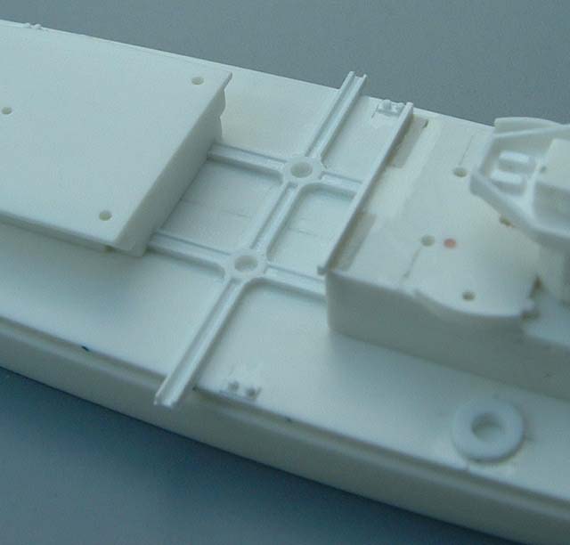 |
|||
 |
||||
| One of the things Neptun is known for is making underlying supports for decks, etc., that can only be seen when the model is placed on a mirror or held upside down. This is not under-cutting per se, such as where one deck resides over another, and thus creates a between deck space that may require a species of internal detailing. However, sometimes the processes involved are similar to what we see here on the Lion's AA gun supports. Once again, the support members are made by a milling machine and we will seldom see these tiny details unless we look very carefully! But they certainly help to provide the extra bit of visual soup that draws our attention. | ||||
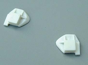
| Breakwaters & Cleats | ||||
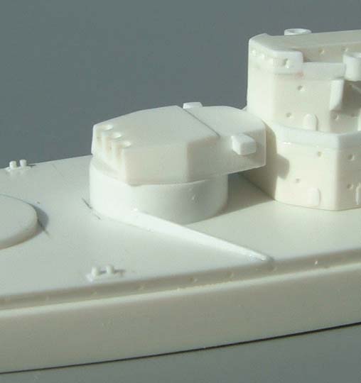
| Getting these bits to blend seamlessly with the deck and surrounding
structures is no easy task. Dave advises:
"The blending technique is hard to explain -- it takes a lot of experience
and practice. The piece is partially shaped with a chamfer, then by using
excessive amounts of glue assembled. The glue softens and melts the plastic,
which can then be moulded into position. Once dry the blending is finished
by sanding. The major drawback to this is that it is quite risky, if you
use too much glue you risk melting the barbette and the deck."
|
 |
|||
| Great care must be practiced where the breakwaters adjoins a barbette or other structure, as can be seen here. It is hard to get good effect lighting, but Dave certainly seems to have mastered the task at hand. Breakwater supports are a related subject, and require a similar technique. | 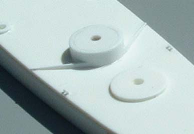 |
|||
| Main Turrets | ||||
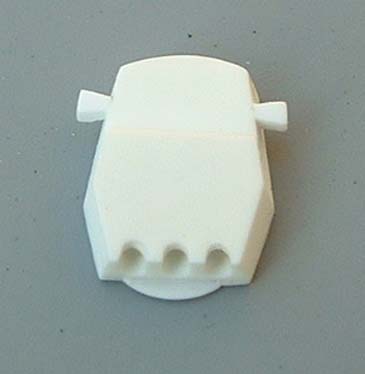
| A milling machine can help ensure nearly perfect cuts in
the plastic blocks that are used to make the main turrets. However, much
handwork is still required -- especially when making the rangefinders and
gun-ports. Dave is attempting something unique here, and thus the need
to get the gun ports to the right depth. As he puts it:
"The barrels are done and will be fitted this evening. One was turned on a lathe in brass and (the others were) moulded from that. I moulded the turret without guns to give an option for fitting barrels in different elevations if needed." This is a neat option, and especially for kit builders. We may also
have some completed models done with the guns arranged in a range-firing
position. There are actually two types of main turrets aboard the Lion,
and both will be represented. They differ in minor details, but in for
a penny, in for a pound. As always, the fit for all elements must always
be checked, as shown here.
|
 |
|||
 |
||||
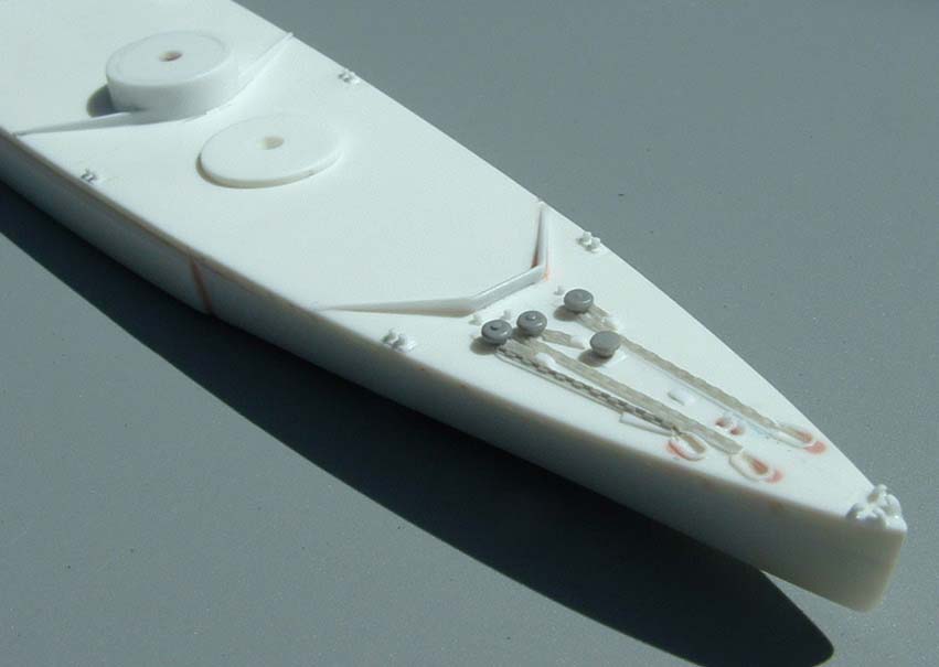
| Deck Hatches and Vents | ||||
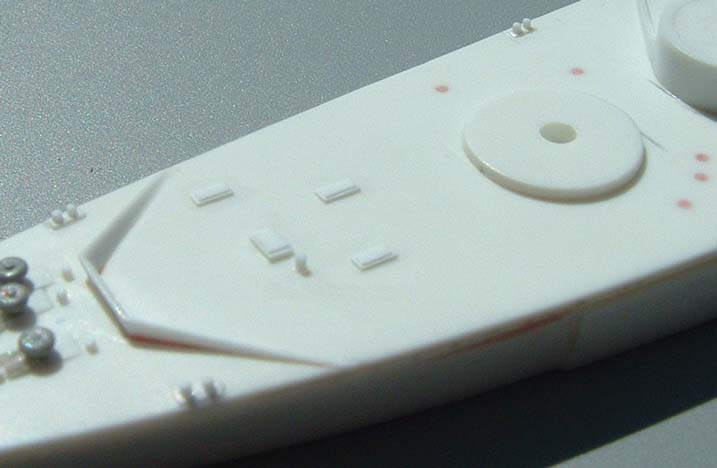
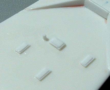
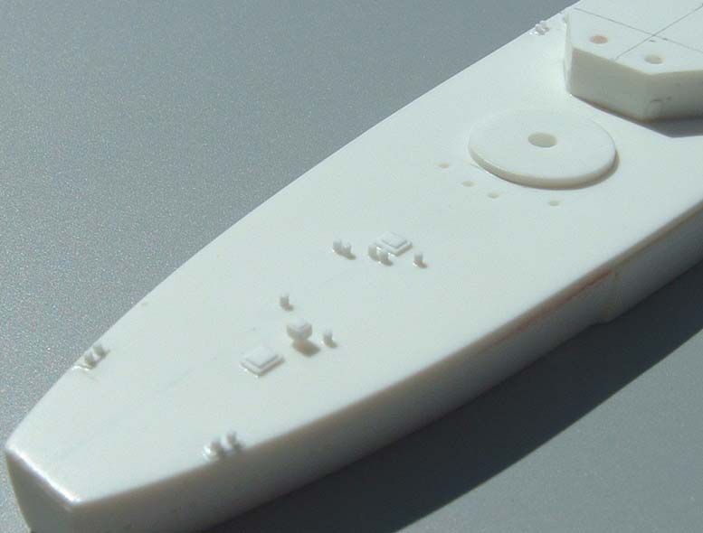
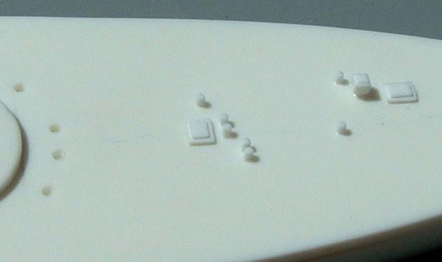
| There is a bewildering array of hatches and vents that
adorn the decks of ships, and Dave is busily at work fitting these on to
the master. As can be seen, a proper deck hatch has a frame that rises
above the deck, and then the hatch itself is mounted within the frame.
I have no idea how Dave manages to work both elements into his hatches
at 1/1250 scale, but he certainly has managed. These deck fittings are
at the forward end, and we can see marks for more elements that will be
located around B barbette.
This is as close as Dave can get with pictures. Dave mills down the edges of the hatches with micro-bits that can shave of a wafer thin section. Dave was going to scribe a wooden deck, but I felt that might be a bit much at this scale. Moving aft, we see a mushroom vent, which is made of two elements, and a series of small vents and hatches. Note the holes drilled adjacent to C barbette. More vents, etc., will be fitted here. The reverse angle shot of the aft section shows how critical it is to locate all parts. One can see the orientation markings laid out on the deck in various shots, although that is not overly evident here. These are matched with a template of the deck that is worked down to 1/1250 scale. Thus, the precise location of the deck fitting can be made with no errors. |
 |
|||
 |
||||
 |
||||
 |
||||
|
|
||||
![]()
© ModelWarships.com