1/350 SMS Konig
Part 1
| Since there are already "in the box reviews" of this kit on the web,
I though it would be best to get right to building it. This will be a multiple
part article that will take you through the steps of building it from beginning
to the end when it is mounted on a base. Hopefully we will reveal some
new techniques that you have not tried yet, and encourage you to apply
some of these tricks to your next kit.
First I would like to say this is a fantastic kit and a great modeling subject, the parts fit together very well, making it a fun project. I choose to waterline the Konig so I could depict it with its torpedo nets deployed. I removed the bottom of hull by using a small drill bit and drilling one hole right after the other along the bottom waterline scribe mark then using an xacto saw. I altered my saw by removing about two inches of the top bracing, this allows me to saw from one hole to the next making for a straight cut along the waterline. A waterline kit also makes assembly of components easier and gluing cleaner, as glue can be applied from the underside. |
Figure 1. |
| I started with the deck assembly by gluing parts ( C-1 and C-2 to B-2 ) we will call this sub section the forecastle deck. Set this aside, then glue D turret ( Barrette ) to part ( B-1 ) this is the main deck section the barrette will help align the forecastle deck section to the main deck section the two sections can now be glued together forming a one piece deck from bow to stern the ( B ) turret (Barrette ) can also be attached. Both barrettes seams should be filled and sanded clean. This one piece deck is now ready to be attached to the hull. The only area of concern was around the seam on the hull side where the two sections meet. This seam will need filled and sanded along with one at the front casement gun position. This assembly sequence worked very well for me. The fit of the deck to hull was very good, the gap being close all around the ship, plus what little gap there was is prefect for laying the photo etch railings along. | 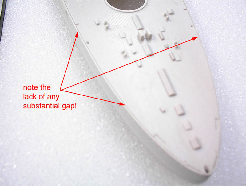
Figure 2. |
| My next step was to assemble parts ( K-11, K-12, J-31, J-43, J -44, and J-45 ) this is the 88 mm gun casement deck and bridge base. I wanted to open a few of the doors to add some realism. The tools used are an xacto knife, pin vice, and a small drill bit just a little smaller than the doorway. The doors are well marked and I used a five inch long square jewelers file to open them up. First I drill two holes, one above the other in the door, those are opened using a xacto knife to cut out the plastic between the two holes. Then using the square file work it into the holes enlarging them go up and down for the height of the door. Do not go any wider than the file. Take your time do not remove too much plastic. If the door opens into a compartment that doesn't have a floor, this can be made from sheet styrene braced to the proper height. I also filed open the openings for the air intake grills supplied with the Gold Medal Models photo etch set. There is also a photo etch set from White Ensign Models which is also very nicely done and includes some parts that are not in the Gold Medal set. | 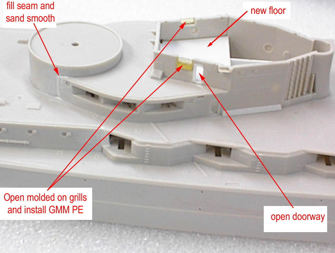
Figure 3. |
| A model ship can look rather mundane when portholes, lookout slits, doors, and vents, are left the same color as the ship or even if painted silver or white. Why not open lookout slits, it's not difficult and it will add life to your ship I will describe how this can be done. The tools you will need are an xacto saw, sanding film, styrene strips (.020 x .060) and super thin glue I use Insta-cure brand. | 
Figure 4. |
| I am going to use the Konig's lookout structure on the foreword mast parts (K-8 and K-4) to illustrate the process. I have already assembled the other two parts in Figure 5. This will give you a good before and after view. | 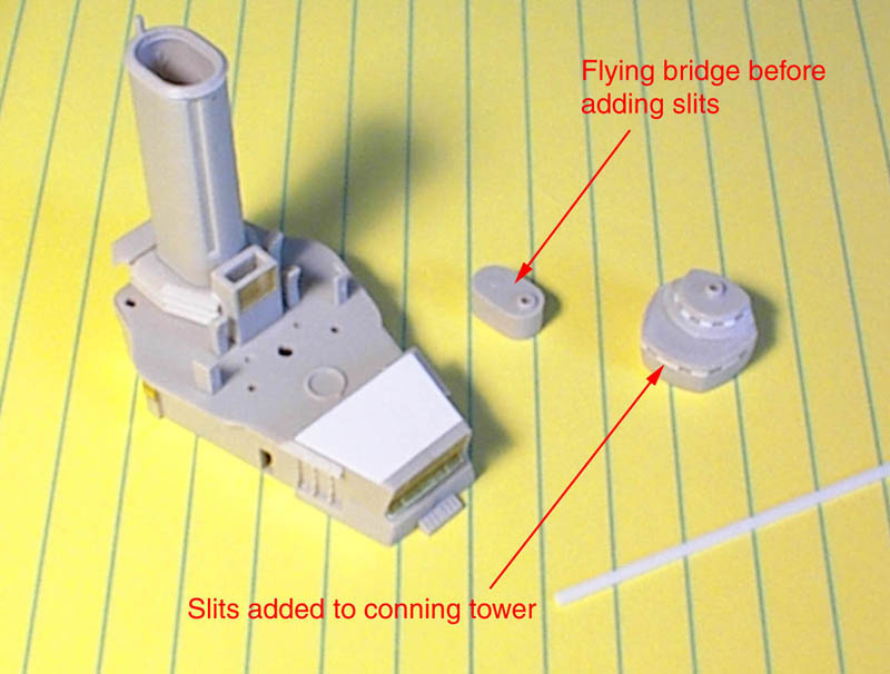
Figure 5. |
| Using the saw carefully saw from the face of the structure about three quarters of the why up back towards the backside of structure keeping level stopping where you want the last lookout slit to be as in Figure 6. | 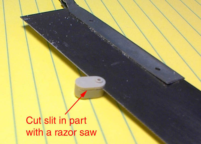
Figure 6. |
| Then using sanding film (fold film to add thickness) insert into slit and work to open the slit to the thickness of the strip styrene. | 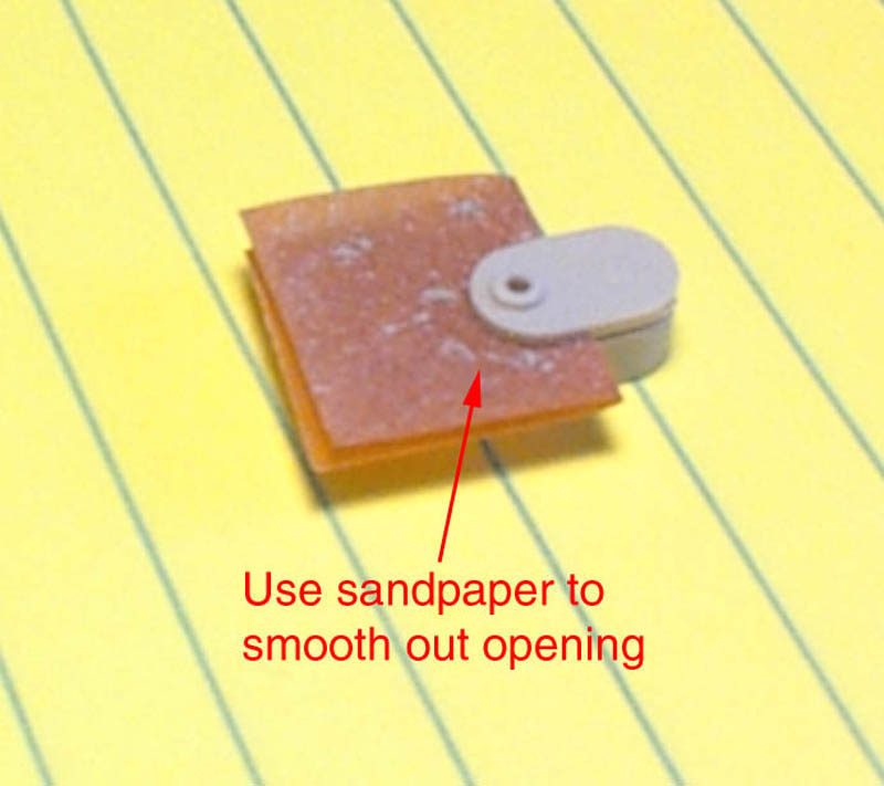
Figure 7. |
| Cut small piece's of styrene strips as in figure 8. and insert into the slits. Using tweezers to position the strips to make equal lookout openings. Once this is completed use the ultra thin glue. I like to use a pin to apply a small amount at a time around each strip, being careful not to use too much. You could easily fill the slits, in if this happens blow it clear before it dries. | 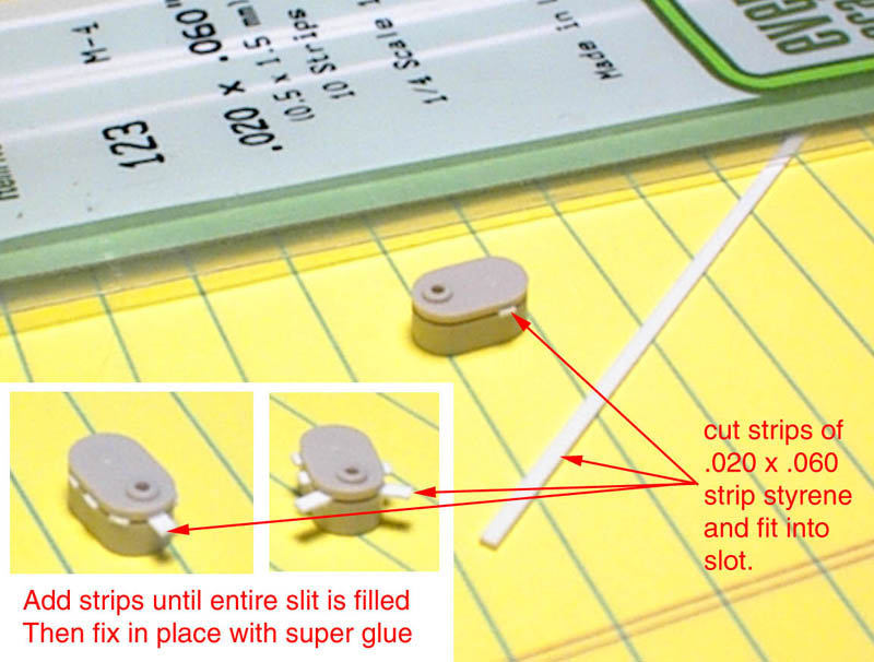
Figure 8. |
| After you have secured all the strips, trim off the excess with finger nail clippers. You can then use sanding film to remove what remains of the styrene down flush with the sides of the lookout structure as in Figure 9. The conning tower is similar, being different only in the complex shape. The way the slits are installed is the same, but when sanding the excess styrene away, I like to roll the sanding film into a small tube the diameter being close to that of the curvature of the conning tower roof, and then carefully sand to shape. | 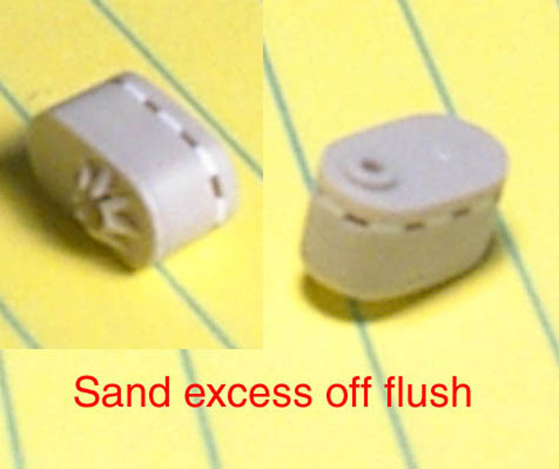
Figure 9. |
| Part 2 covers painting the deck and superstructures. This iincludes
masking, paint colors, paint mixing, and the spraying of the paint.
Thank you, good luck and have fun.
|
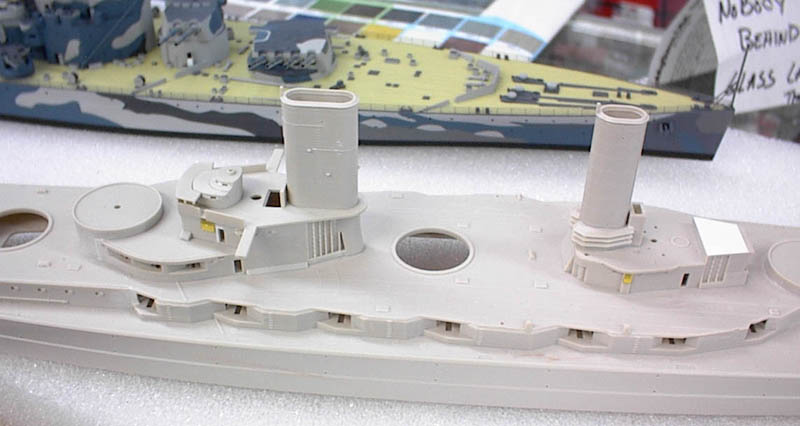
Figure 10. |
| Webmaster's Note: Andy is not online at this time. Please post your questions on the message board. | |
