Building Trumpeters
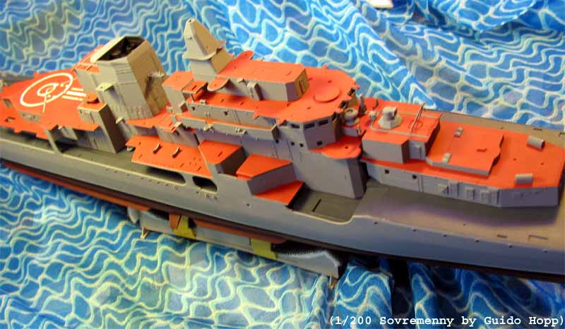
1/200 Sovremenny 956
A/E
by Guido Hopp,
Düsseldorf, Germany
July November 2002 |
|
|
Colours, Coats and Mixes:
All colour coats Tamiya, Clear Coat Revell MATT 2
(All colours and coats applied by airbrush, touch-ups applied with
fine Tamiya art brush):
Decks: Superstructure: Tamiya 50% Flat Yellow(XF-3)+ 50% Flat
Red(XF-7), tanned down with 5-8% Flat Brown(XF-10) and a few drops of white,
if you want the deck to have a more orange tint carefully add XF-7 only
Weatherdeck: German Grey(XF-63) + 20% White(XF-2) + 15% Flat
Blue(XF-8)
Upper Hull and Superstructure: Neutral Grey(XF-53) + 10% White(XF-2)
+ 10% Light Blue(XF-23)
Anti Fouling Red: Flat Red(XF-7) + 30% Red Brown(XF-64) + a few drops
of Flat Black(XF-1)
Flat Black(XF-1), Flat White(XF-2)
Life rafts and radar dome: White(XF-2) + 10% Light Sea Grey
(XF-25)
All colours thinned with Tamiya Thinner(X-20A) 2:1
References: Various internet pages; Photos by Mr. Mark Meredith,
provided by Mr. Doug Hallet;
Moderne Kriegsschiffe Motor Buch Verlag
Aftermarket additions and replacements by White Ensign Models
(WEM)
Scratch: Flower Class Scratch, GMM Photo Etch (PE) for 1/350
Yamato, GMM PE 1/350 doors and hatches, GMM PE 1/350 cable reels, Eduard
PE for 1/350 Yamato |
|
|
More than once I stood in my hobby shop, looking at the
Trumpeter
1/200 Sovremenny box. Being a fan of WWII vessels in 1/350, I never
seriously considered buying it, although I can not deny that certain itching
in my fingertips.
On our honeymoon trip in June my wife and I stumbled over a small hobby
shop with a huge range of ships, while staying at Beijing. There she was
again (The ship not the wife!) and being sold at about US$ 35 I gave
in to temptation.
Being back home, the kit wasnt shelved for long.I worked out a trade
with an American friend for the new White Ensign Model Sovremenny PE set,
and the project was back on track. |
| While I was waiting for the PE to arrive, I started to
look for picture reference. On the internet there were plenty of pictures
available showing the whole ship, but almost no detail shots. Even WEM
was not able to supply books containing such detail-pictures. Only when
I was well in the building process, Mr Doug Hallet form Seattle provided
pictures to fill several books on the Sovremenny Class. The pictures were
mostly taken by Mr. Mark Meredith, who was attending a ships tour in the
80s. To both of them I owe a great deal of gratitude. |
Initially, coming up zip on picture references, I had no
choice but to build the kit out of the box, only adding WEMs PE and their
replacement kit for the AK-130-MR-184 130mm turrets. (This would be the
right spot to again praise WEMs prompt delivery.) Still lacking the PE
sheet, I started cleaning up the hull with Tamiya Sanding Paper (320 grain)
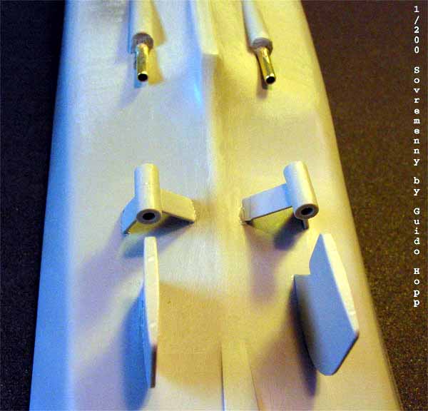
and a glass-polishing tip for my Dremel. The shafts and rudders supplied
for the kit are designed to work on a motorised version of the kit. There
are no parts specially designed for a static model. First I installed the
shaft suspension. After that I cut away the holding pins on the rudders,
which is necessary to properly fit the rudder/rudder-suspension parts to
the hull. Additionally to the metal shafts, brass shaft tunnels are provided.
I placed the shafts together with the tunnels into the suspensions and
hull. I let the tunnels stick out of the hull for about 15mm and filled
the remaining gap between the tunnel and the hull with Italerie putty from
the inside of the hull. I let the putty dry just long enough to be able
to cut away the excess putty on the outside of the hull with an Exacto
blade.
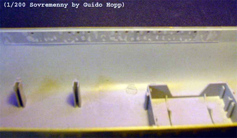
I drilled open the portholes along the hull and backed them with transparent
Plastruct 0.5mm styrene sheets and covered them with little paper balls
to prevent them from being painted. |
click images
to enlarge |
 |
 |
|
|
The kits paint instruction refers to Mr. Gunze colours,
which were not available in any of the six hobby shops in Düsseldorf.
So I decided to stick to my colour coats of choice by Tamiya. Not being
able to exactly specify the colour used on the Sovremenny, I mixed the
colours by guess work looking at the pictures available on the internet
(Not a very professional approach, I admit that, but it looks OK).
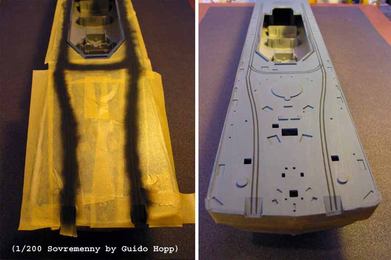
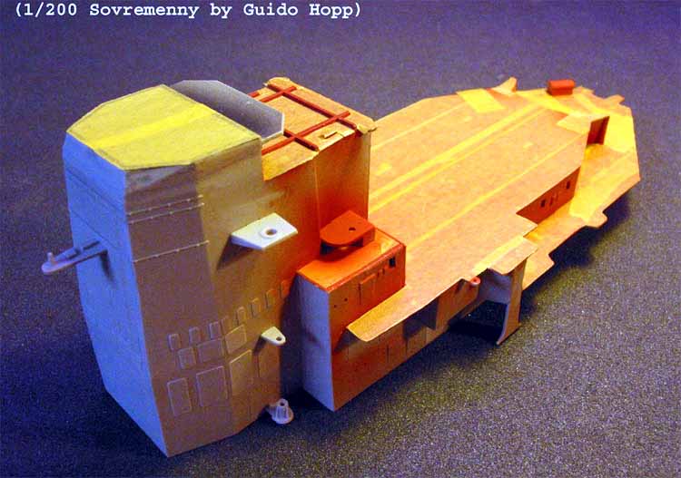
Following the available pictures of the ship I painted the hull beneath
the white waterline all black. (Only later after I already had installed
the best part of the superstructure, I learned that beneath the white waterline
there is a 3 black boot topping and all the lower hull was anti-fouling
red.) The black lower hull was masked off by Tamiya tape (IMO the best
for the purpose) and the upper hull was painted light grey. The white waterline
was done by free hand masking the upper portion of the hull, while the
lower portion was still masked, leaving 1mm space between the tapes. |
| For protective reasons I always leave the hull masking on until all
superstructures are applied onto the deck. Fitting the deck was done as
given in the instruction booklet. The fit was accurate, so only the gap
between the main deck and the quarterdeck needed filling. Again I used
Italerie putty for this purpose. Further on, I painted the deck dark grey
masked off the jettison rails, painted them black and applied a clear coat.
(Unfortunately, there was a remainder of dried-out white colour in the
feeding tube of my bottom-feed airbrush, so I splattered a zillion white
micro-spots onto the quarter deck, which had to be removed and over painted.
That is why the quarter deck colour looks uneven. Next day I bought a new
feeding tube, which I will exclusively use for clear coats in the future.) |
 |
| Here I was: A happy modeller! Right in the middle of a
build with hundreds of parts to come, content with the progress made and
looking forward to the things to come: How could I know about the storm,
that was brewing up behind the horizon? |
Impatiently waiting for the WEM PE to arrive, I started
to work on the superstructure. Following the order of the construction
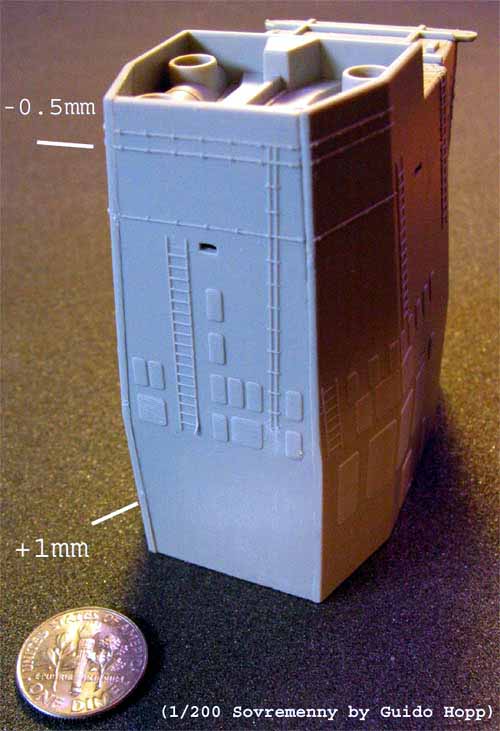
manual, I started with the funnel. I cut the parts from the frames
...and that was already the end of what I would call an easy build.
Due to poor mould alignment there were moulding lines all over all the
edges of each part. There was no way of getting these together properly
without giving every part a mayor clean-up along the edges. Next worse
thing, is that the parts do not have positioning pins and holes, which
makes it difficult to assemble the parts in proper angles and relation
to each other. As the moulding seams along the parts edges required intense
filing and sanding, subsequently the parts fit suffered. Whatever I tried,
I didnt manage to assemble the parts without having big bad seams (between
-0,5 up to +1mm) all over the place! With all the details such as funnel
grills so close to these seams it took quite an effort to remove these
seams by cutting, putty-filling, sanding and polishing without damaging
the surrounding details.
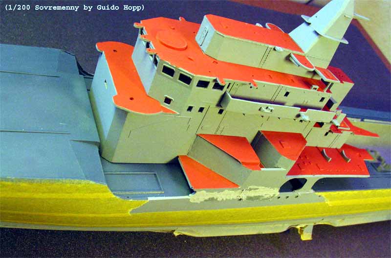
Being inexperienced in working up such inaccuracies, it took almost
a day to finish the funnel alone. Another day I spent assembling the aft
SA-N-7 deck and the helo-deck with the control rooms next to the hangar.
The same fitting problems inhibited a speedy build. Cutting open the windows
and the removal of doors and ladders were the only easy steps in the process
and were done by using a scalpel and the Dremel polishing tip. Painting
the inside of the funnel top with various layers of highly thinned black
(to simulate the uneven look of soot deposits) and airbrushing the decks
came next. Masking the decks concluded the basic build of superstructure
segment 1. |
 |
 |
|
|
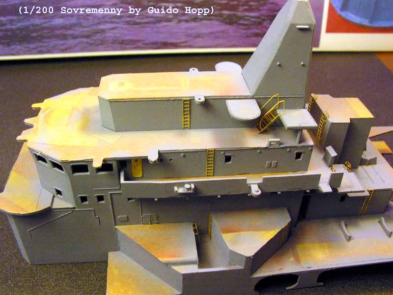
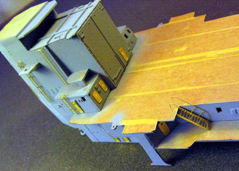
| The boat deck wasnt a bit easier than the aft superstructure. Additionally
the tips of the port side of the lower boat deck was twisted down- and
starboard side upwards. Fortunately this wouldnt have an impact on the
model, as these parts could be forced into their proper positions later
on. The assembly was pretty straight forward, as I got used to mayor cleaning
and shaping methods. Even the assembly time on this segment had gotten
better. |
 |
|
|
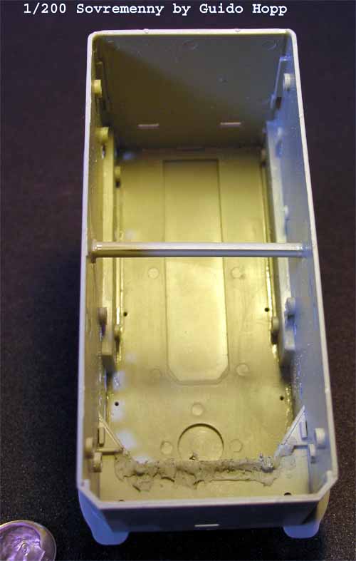
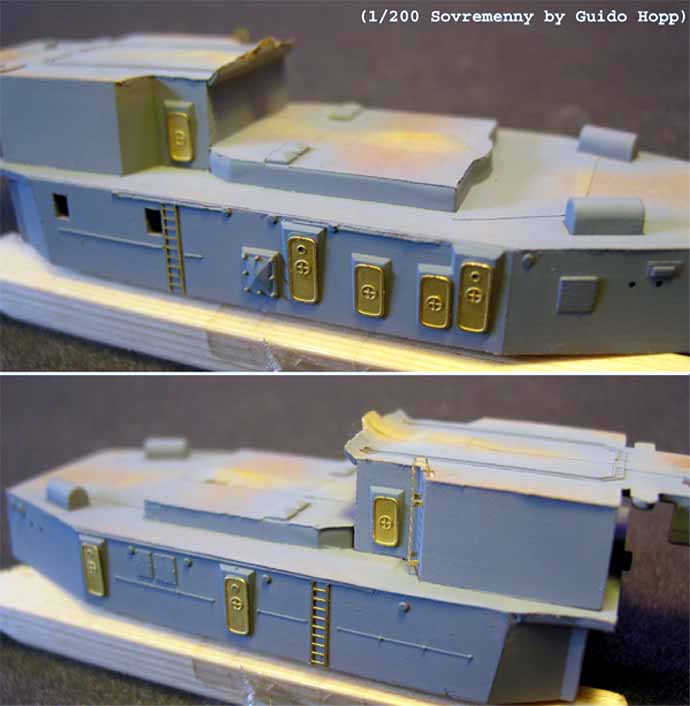
| After cutting out the windows, I encountered the same fitting
and assembly problems, when I commenced to build the bridge section. This
time I added a beam to support the stability on the lower portion of the
structure made from sprue.
As well, I recommend to frequently check the fit of the superstructure
to the deck while glue is not fully hardened, as a rectangular assembly
is not guaranteed and the connecting surface might not be level (on the
first try there was a 1mm gap between the deck and the starboard side of
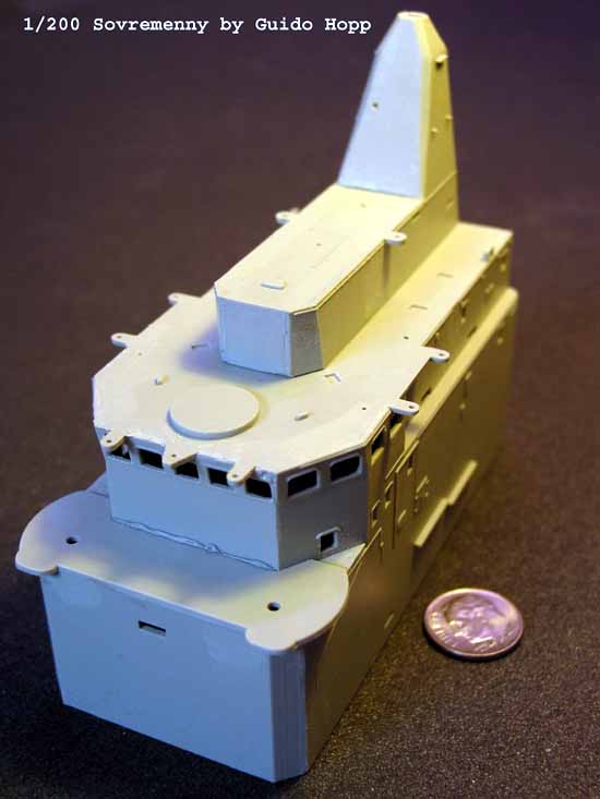
the bridge). The pyramid shaped base of the fore mast and the sensor platform
beneath were easy to assemble ( ... but still proved to be a pain in the
back, as itll turn out later on). The bridges wing platforms, sensor platforms
and aft walkway were added, painted and masked after having filled the
0,5mm gap between the bridge and the forward AK-630 platform. |
|
|
| To assemble the SA-N-7 launching and upper sensor platform on the focsle
was by far the easiest step til here. Especially since the arrival of
the marvellous WEM PE spurred my motivation on the process. |
 |
|
|
| I reined the zeal to start using the PE and went on connecting the
boat deck to the Bridge section. As predicted, the positioning rails alongside
the bridge straighten the bend boat decks wings. Sensor platforms and
control rooms on either side of the bridge were to be installed next. This
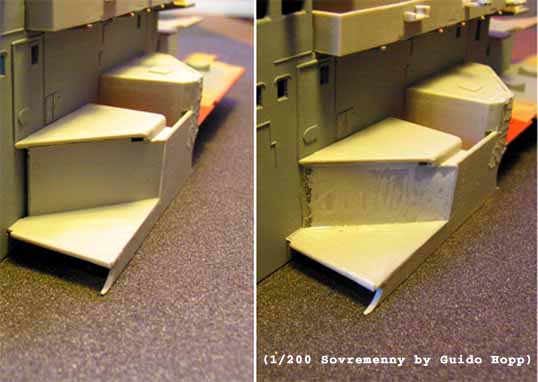
proved to be one mayor problem of assembly. First, the angled wall of the
forward control room, designed to divert the blast of the SS-N-22 was not
long enough leaving a good 1mm gap open towards the bridge side and a minor
gap at the edge of the forward deck. As well the roof of that control room
didnt fit either. A square hole approx. 1 x 1.3mm remained open on the
upper outside of the connecting line of roof to wall. All gaps I covered
with layers of 0.5mm styrene sheet. This procedure was necessary on both
side of the bridge. Having concentrated on the above problem I overlooked
an even bigger glitch in the model. |
 |
|
|
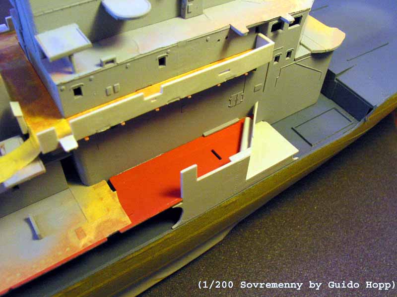
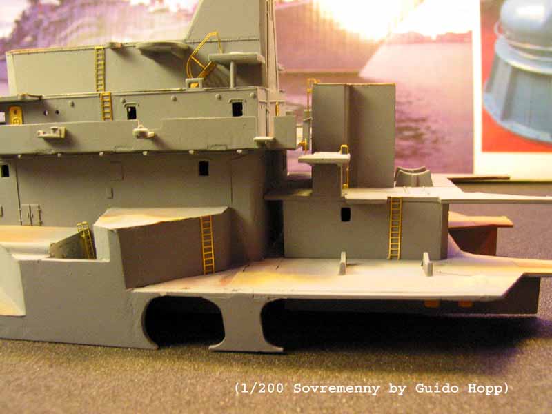
| Ideally those control rooms on either side of the bridge
should connect almost seamlessly to the hull sides. As the kit is made
to satisfy the need of R/C modellers the bridge section can not be fixed
to the hull to provide access to the hull permanently. So the completed
bridge section is made to be fitted on the deck instead of the hull, being
1.5mm too narrow. Due to the fitting qualities of the kit, these crucial
mm were lacking only on the starboard side, while the port side control
room perfectly lined up with the outer hull. I had two choices: Either
removing the control rooms again and fill those 1.5 mm from the inside
or cover the distance by adding to the outside. I decided to do the latter,
because it seemed to be easier. As well, removing the glued on control
rooms would pose the danger of mayor damage to the rooms, the bridge and
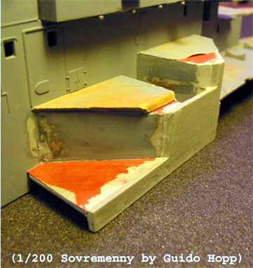
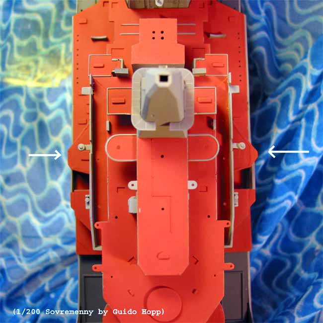
the boat deck. I reconstructed the outline of the complete outer section,
over sizing it just a little bit to come up with some room to manoeuvre
the part into place. That required a second part to widen the port side
boat deck. I glued it on, after removing all walls, which were standing
alone (between the control rooms and below the boat deck) and filed it
to exactly match the remaining parts. The procedure worked out nicely,
but had two disadvantages: 1. The walls, which I removed earlier are now
1.5mm (30 scale cm =12) and 2. The bridge section is not symmetrical any
more, which however, will become obvious in the overhead perspective only. |
 |
 |
 |
|
|
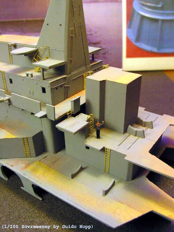
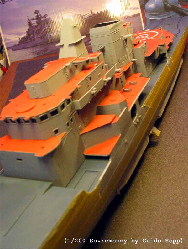
| Having gone through nightmares, sweat and many curses,
I went on to use the PE for the first time. (Note: To better show the PE
parts, I applied a first layer of paint. That, I usually not do before
all integrated parts like doors and vertical ladders are fixed.) For a
detailed description of WEMs PE for Sovremenny check out Timothy
Dikes review of that set. |
|
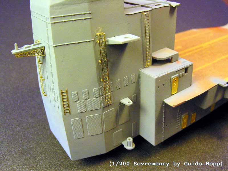
As the WEM instruction does not indicate the placement of doors and ladders,
I used the PE only in spaces, where they had previously been moulded on.
10 doors and 4 hatches of the PE were left over. Support brackets and struts
of the funnels sensor and antenna platforms came next. |
Furthermore, I cut and pre-shaped the railings for all superstructures
at this point, labelled them with stickers and placed them in a padded
box for later use. (Once the superstructures are placed on the hull, access
to their decks will just not be as easy due to the size of the ship, especially
on my relatively small workbench.) Inclined and some vertical ladders shown
in the pictures are just pre-shaped and not yet fixed, as they would be
damaged upon removal of the decks masking.
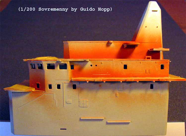
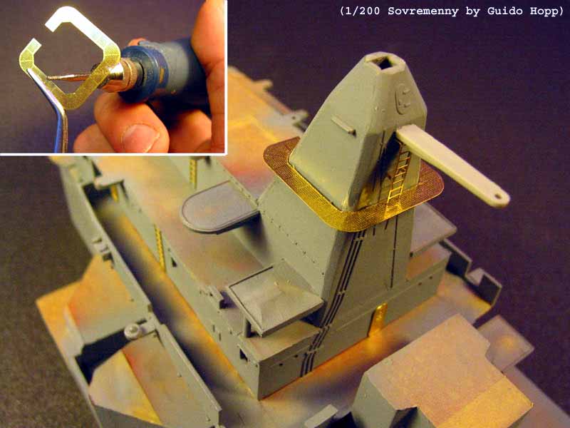
Fitting the walkway on the pyramid shaped foremast proved to be very
tricky. To place this part onto its moulded-on positioning struts required
extensive filing on the pyramid as well as complete removal of the inside
solid rim of the walkway itself, using a diamond cutter for my Dremel.
(Note: The aft antenna platform above the walkway will be replaced by a
PE part later on). I applied a second layer of grey and a first layer of
clear coat. Last came the clear window backing for all superstrutures,
made from clear styrene sheet. |
 |
|
|
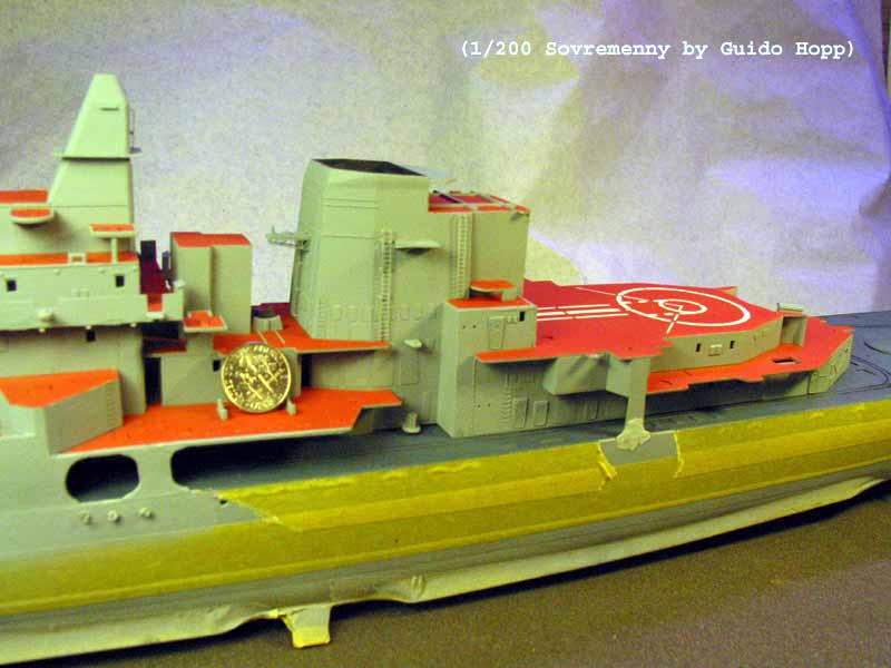
| After having applied a second layer of grey and first clear coat to
the funnel I went on to prepare fixing the superstructures to the hull.
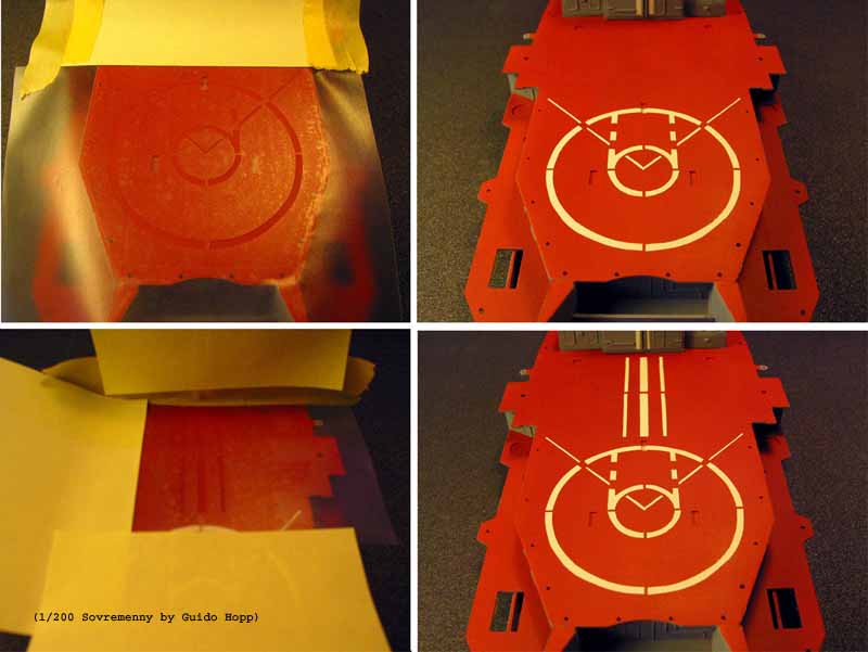
Before I would do that, I decided to put on the flight deck markings on
the helo deck. I have to admit, that I hate using decals. On past projects
I faced all the problems a modeller can have with those: Poor alignment,
silvering, air bubbles,
you name it! The very big decal representing the
helo deck markings gave me a headache even before I started the kit. Now
was the time and I screwed up
again! When I tried to slide the decal
off its carrier it folded up and broke. Damn! Having had a gut feeling
about it, I had taken the measurements of this decal earlier, to be able
to make a mask, if needed. I painted the marking in two steps and added
an initial first clear coat |
 |
|
|
After having removed all deck masking, I fixed the superstructures
onto the deck: Bridge/Boat deck first, funnel/helo deck second and forward
SA-N-7 Platform last, always filling the seams between hull and the attaching
walls of the superstructure with putty. Filling and sanding three to four
times, the connecting line almost completely vanished.
At this point I received the pictures from Mr. Doug Hallet and I learned,
that the connection between hull and superstructure is not at all seamless.
Well, it was too late to change that now.
As well, the info about the black boot topping and the red lower hull reached
me now. Id say just in time to straighten that mistake out. I masked the
boot topping line, placed the model up side down stably on piles of books
and added an apron form old newspaper to protect the upper parts. First
I applied one layer of red, then a clear coat. Two more layers of red and
a finishing double-layer of clear coat did the job just fine. |
End of Part 1
Back to Menu
On to Part 2 |