by Martyn Robey
| Historical Background
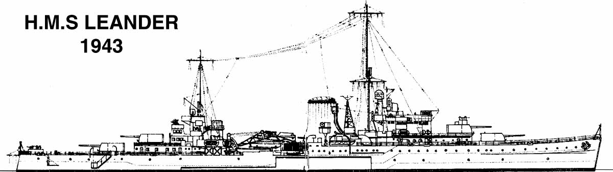
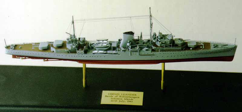
The Leander was a sister ship of the light cruiser Achilles. She was at sea on active service for a great part of WWII, in New Zealand home waters, the Tasman and South Pacific, in the Indian Ocean, Red Sea, Mediterannean and, the subject of this brief background for the model itself, the Solomon Islands. This area had become the focus of naval operations against the Japanese. At that time Japan had command of the seas at night. They would run forces and supplies down The Slot, as New Georgia Sound was referred to, on destroyers and cruisers, known as the Tokyo Express, to New Georgia. This battle was one of many that were played out in those extremely dangerous waters. Like all good battle stories, it is a story of high drama, heroics and final triumph. Detailed to join Task Group 36.1 a week after the US light cruiser USS Helena was torpedoed and sunk, HMNZS Leander found herself under a bright three-quarter moon, on the night of 12/13 July 1943, steaming at 28 knots to intercept the Tokyo Express from Rabaul, attempting to reinforce Vila, on Kolombangara Island. Ahead of the cruisers Honolulu, Leander and St. Louis were the destroyers Nicholas, Taylor, Buchanan, Woodworth and Jenkins. Disposed in line astern, a thousand yards apart and far to the rear, were the destoyers Smith, OBannon, Radford, Ralph Talbot and Gwin. These destroyers came from many different squadrons, none had worked before with the cruisers, and none had operated at any time as a single tactical unit under the group commander. As the fleet proceeded in single line past the northern tip of New Georgia into Kula Gulf a patroling Catalina made radar contact with an enemy group 26 miles away, steaming due south at 30 knots. It was a Tokyo Express, under the command of Rear Admiral Shunji Izaki with 1200 infantry reinforcements and supplies aboard four destroyers, Yunagi, Amatsukaze, Satsuki and Minasuki which were accompanied by five other destroyers; Hamakase, Yukikase, Mikazuki, Ayanami, Yugure and the cruiser Jintsu. 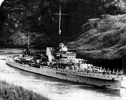 As Leander straightened out to follow the cruiser St Louis, which minutes previously had followed her, she was rocked by a giant explosion at 1:25am as a torpedo struck her amidships on the port side around Frame 87. After the impact Leanders engines stopped. The force of the blast ripped a hole about 30-feet long and 20-feet high in the No. 1 boiler room, where all those on watch were killed, and threw up a huge column of water that swept several men overboard. It also travelled up a boiler room fan casing to hurl seven men of a 4-inch guns crew into the sea. The port quadruple torpedo mounting was shifted several feet aft, leaving the torpedoes dangling over the ships side. In all, one Japanese torpedo claimed the lives of 28 of Leanders men. The New Zealand cruiser was in no state to continue the fight. The biggest task ahead was, if possible, to save the ship. Meanwhile the battle continued. Some 40-minutes after Leander had been torpedoed, tracks of more torpedos were seen approaching Honolulu, three of which passed close ahead of the flagship. One went under her stem. Two more barely cleared her stern. St. Louis wasnt so lucky and was struck on her port bow, slowing her to eight knots. Two minutes later Honolulu made a sharp alteration of course and took a torpedo hit on her starboard bow. The destroyer Gwin also received a blow which set her afire and jammed her rudder. Honolulu made yet another severe turn to avoid Gwin and was hit near the stern with a torpedo which failed to detonate. After these successful attacks the Japanese force, which had discharged a further twentysix torpedoes, withdrew northwest to their base at Shortland Island. Honolulu and St. Louis were able to steam at fifteen knots while the scattered destroyers assembled to screen the stricken cruisers. But while attempting to tow Gwin, Buchanan collided with Woodworth, damaging her propeller and flooding three after compartments. One of several depth-charges knocked overboard exploded near Buchanan giving her a tremendous shaking. Throughout that long day Leander laboured resolutely to make it back to Tulagi. How this was done became a classic of naval damage control. A second destroyer, Jenkins, joined Leander and circled ahead, whilst Radford searched for possible submarines astern. Gwin, somewhere behind, and attended by Nicholas, came under attack from enemy aircraft. Fighter escorts eventually arrived and after numerous dog-fights drove off the Japanese. Leander, with a 600 square feet of her side structure blown open to the sea; the forard boiler room, main switchboard room, forard dynamo room, low power room, and the transmitting station where all gunnery control information went through the computer, completely flooded, five fuel tanks wrecked and two others badly contaminated by sea water, big leaks through major parts of her bulkhead structure, she looked a write-off. It was found, however, that by cross-connecting her boiler systems, by backfeeding intricate machinery below, the ship could steam slowly on two engines taking steam from C boiler-room. While she headed slowly back to Tulagi, escorted by the US destroyer Radford and fighter air cover, six bodies of Leanders crew were buried at sea. On arrival at Tulagi, work immediately began to patch up the hole in her side to make her sufficiently seaworthy to make the passage back to Auckland under her own power. Tons of cement were used to make a temporary patch and Leander, escorted by Radford, sailed from Tulagi on 25 July, 1943 and arrived in Auckland on 29 July. Almost a fortnight after the action, when she was in Devonports dry dock, Leander was still giving up her dead. After being patched up by New Zealand Naval Dockyard workers, Leander sailed for the Boston Navy Yard in Massachusetts on 30 November to undergo permanent repairs and radical changes to her armament and appearance that would take a further two years. She took no further part in hostilities.
|
|||||||
|
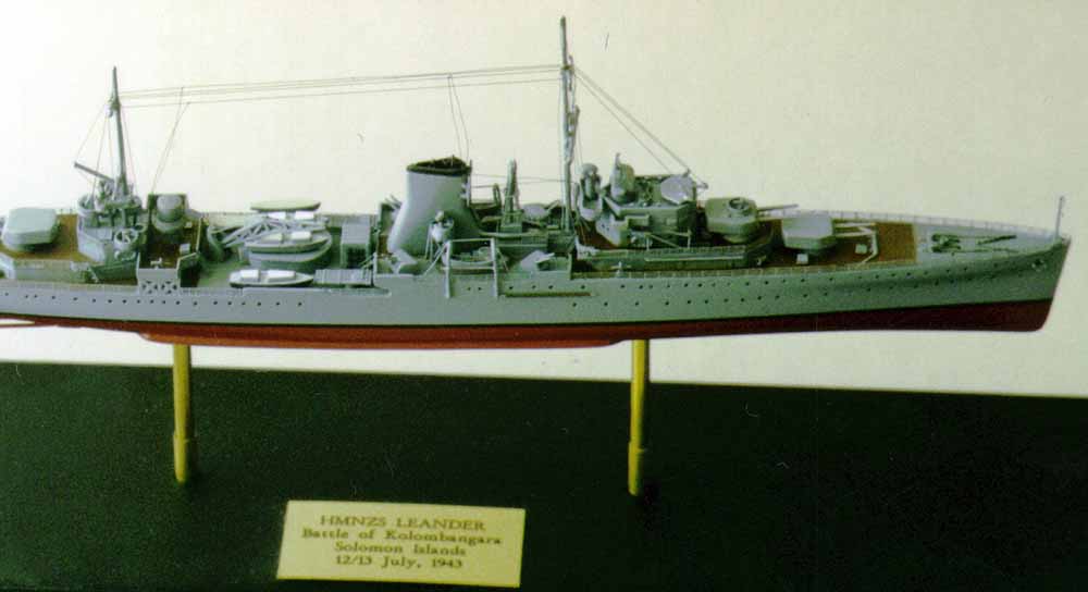
The Kit and References As best as I can remember, as it took me a year to complete this model, this article describes what I needed to do to convert the 1:600 scale Airfix kit of HMS Ajax (c.1939) into a model of HMNZS Leander as at the Battle of Kolombangara, 1943. It entailed continuously checking references, scratch building many parts and pirating bits and pieces from other kits. Appearing in 1965, the 1:600 scale Airfix kit is the only plastic injection- moulded kit of a Leander Class light cruiser, and is very sparse in detail and with many sink holes. My references were limited to the excellent book by Jack Harker titled Well Done Leander, Portrait of the Royal New Zealand Navy by Grant Howard, Blue Water Kiwis by Matthew Wright, The Royal New Zealand Navy by Michael Burgess, New Zealand Naval Vessels by R. J. McDougall and Australian & New Zealand Warships 1914 1945 by Ross Gillett. |
|||||||
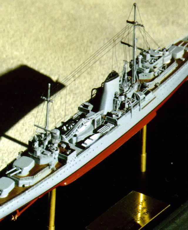
Hull & Deck Modifications The first step was to drill out all the port holes. These are clearly moulded on the kit. I used Tamiya masking tape to create a plumb line, so that all the port holes would be drilled out in a straight line. As it turned out I drilled out more than was required as Leander at this stage of her career had a number of her port holes covered over. I should have checked my references closer. Fortunately I dont think that this error detracts from the finished model. I also elected not to glue on plastic card, cut to shape, to represent Leanders armoured hull plating amidships. This is represented by etched lines on the kit itself, which unfortunately have all but disappeared due to sanding and paint. Like many ship modellers, I planned to display this model supported on brass tubing pedestals within a glass case. To do this the models hull needs to be somewhat reinforced to allow for the drilling and insertion of these pedestals. This was achieved by first of all strengthening the main decks with strips of plastic card glued athwartships, or widthwise, about 15mm apart. The two hull halves were then glued together and a length of balsa wood was carved to conform to the hulls internal shape, inserted, and secured in place using PVA glue. PVA glue was poured onto the top of the balsa wood insert to take up any voids. I then fitted the upper main decks in position to ensure that the hull conformed to the correct shape as it cured. The decks were able to be removed after the internal glued balsa insert and the additional PVA had all dried, which now made a nice solid unit. My intention was to build this model as a number of completed individual structures that would, eventually, come together in a final assembly. Close inspection of photos and diagrams of Leander reveal there were significant detail differences between her and her sisters. Leander carried her two whaler seaboats between her secondary 4 armament. So the forard 4 mounts to port and starboard will need new positioning holes drilled as will the davits for the seaboats. The old holes need to be filled and sanded smooth. The splinter sheilds, moulded onto the hull, will also need to be trimmed off and repositioned later with plastic card. On the kit there are also 01 deck wing extensions carrying quad 0.5 AA guns. These deck wings, and their supporting cross bracings moulded on the hull, need to be removed, leaving the deck flush with the deckhouse bulkheads below. I also removed all the Aztec steps from the kits decks as these were to be replaced with Toms Modelworks photoetch ladders. Likewise the moulded anchor cables on the focsle were sanded smooth and then replaced with photo etched versions. A capstan was also made from plastic rod. After a number of accidents on the real ship, which resulted in both of Leanders irreplacable Walrus aircraft being destroyed, it was decided in Alexandria, in June 1941, to remove the now redundant catapult altogether. This deck now effectively became her boat deck. On the kit it is necessary to remove the top turntable from the catapult mounting and replace the top of this structure with a thin plastic card deck. On the kit the actual catapult deck has moulded in planking. This needs to be sanded off, as this was a steel deck supporting not only a catapult, but also a large crane. I elected to use the kits crane, but enhanced it somewhat by cutting out the spaces between the framing with an Exacto knife, and adding some fuse-wire cabling. What was the boat deck, with its outrigger sponsons, now had a radar centred on it with 20mm Oerlikon AA mountings on each of the decks wing extensions. This deck also had enclosed sides. It was therefore necessary to scratch- build the radar from plastic rod and box section plastic card and enclose the decks sides with strips of plastic card cut to the same height as the ships railing, leaving spaces for the two ladders ascending from the boat deck. Further aft there are more 20mm AA gun tubs. Two are located on the after deckhouse and a further two are positioned in individual tubs, side by side, at the stern. These tubs at the stern (and also on top of B turret) were in reality octagonal. I used brass tubing, however, to simulate mine. You will not find any 20mm guns in the Airfix kit. I used ones from a Revell kit for USS Flint. You will need to source a supply of 20mm AA guns as Leander had them not only in the aforementioned locations, but also either side of the bridge superstructure on the main deck. Thats a total of 9 20mm AA guns, if youve lost count! |
|||||||
|
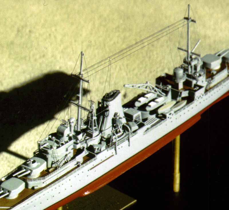
Masts and other enhancements The Leander did not have the tripod mast that comes in the kit, so I made new ones using fine steel rod. I ran sandpaper over the surfaces of the rod so that the super-glue would take. I created a pencil diagram of each mast, measuring the kits ones as a guide, on a flat board, so that the masts and yards were correctly located and square. If you intend to rig a ship you would be advised to construct steel rod masts rather than use the comparatively soft plastic kit-supplied ones, so that your masts and yards do not contort as you complete the rigging process. A very special feature that only Leander had, was the American HFDF radio direction finding antenna mounted on a lattice mast between the forard mast and the funnel. I scratch-built this from plastic strip and 5 amp fuse-wire, which was a pain, as it took several attempts. Next time I shall use an appropriate photoetch lattice mast. The antenna itself was cobbled together using bits of photoetch. On close inspection of photographic reference you will see that Leander had RAS (replenishment at sea) derricks and booms on 01 deck, to either side of the front of the bridge superstructure. I made these from 15 amp fuse-wire and rigged them with 5 amp fuse-wire. You will need to cut off short lengths of fuse-wire first and then straighten them by rolling them flat under a hard ruler on a hard flat surface. Then you can measure them with dividers and cut them into the lengths you require. Boats booms were also made from 15 amp fuse-wire. They were attached to the hull sides by putting small right-angled ends on the booms and locating those ends into drilled holes. When separating one of the quadruple torpedo tube mountings from the sprue, it decided to jump ship, and launched itself into the great unknown, also known as my studio. After a bout of name-calling, the part still failed to materialise. What to do? I certainly didnt want to scratch-build those tubes! Purists will blanch, but I finally used the tubes from the Tamiya USS Fletcher kit. These required the trimming of one launch tube off each and cutting off the blast housing on one of them. I then glued small rectangles of plastic card on top of the tubes. The detail on the Tamiya tubes brings them alive, whereas the poor old Airfix jobs looked like large air-beds! Naturally, after making these new tubes, I found the one that I had earlier lost! The after deckhouse superstructure featured 26 openings covered by square hinged ventilation plates. You could make these from 0.3 X 1mm plastic card. I didnt. I did place photoetch weather-deck doors in eight locations though!
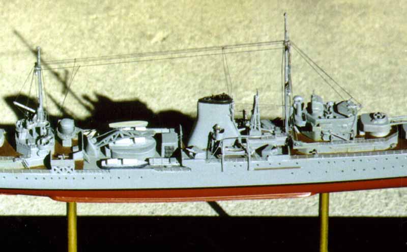
Vents, pipes, lockers and hatches You will need to really study your research here. Lets start at the top, then work our way from the focsle to the quarterdeck aft. The funnel on the kit is totally bare of detail. Because it is so prominent a feature, it screams out for comprehensive detailing. First I glued in some internal supports and then glued in place the two engine-room exhausts, using aluminium tubing. Over the top of the funnel there was a frame, to suport a canvas cover that was utilised during maintainence periods, when the boiler-rooms were shut down. I made this frame using 5 amp fuse-wire. I glued in the fore and aft length first just inside the funnel lip. Then a number of lengths, running across at right angles, were glued to the insides of the funnel and the fore and aft length. On the front of the funnel there was piping for two ships sirens and other piping between them. The siren piping, made from stretched sprue, starts at the base of the funnel and near the top of the funnel they are supported on two siren platforms that protrude from the front quarters of the funnel. The siren supports were constructed using slithers of square U section styrene strip. White Ensign models produce photoetch detail for these siren platforms, which I will use next time. Lower on the funnel there are two engine-room vent pipes. The engine-room vent piping emanates from two holes, that you will need to drill, just abaft the mast on 01 deck, and has a number of intricate elbows in it before going into two holes drilled near the base of the funnel. I made this piping from aluminium rod, carefully bending it to the correct shapes. Now lets go up forard. Just behind the breakwater, on the focsle, there are a number of vents. Drill some holes and glue in some tiny pieces of stretched sprue. I added hatches, made from little squares of plastic card, adjacent to each of the main turrets; on the starboard side foard and on the port side aft. On either side of the funnel there are three engine-room fan casings in line ahead and just forard of them, at 45°, are 4 ready-use ammunition lockers. I also placed two ammunition ready-use lockers on the new radar deck and a hatch on the searchlight platform aft. An additional detail to the after superstructure was a galley stove pipe. This was on the starboard side under the searchlight platform. I made it out of aluminium rod, bent to the correct shape with a T (should have really been an H) wind protection junction at the top. On the kit there is also a slab sided cube of a structure that is just ahead of the catapult mount. Reference shows that this structure had grilled sides to port and starboard. I fabricated these by cutting small rectangles from very thin, square- textured plastic and white glued them in place painting them dark grey and then dry brushing them in light grey. |
|||||||
|
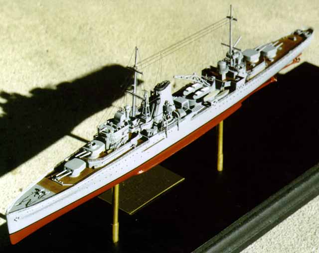
Boats and Floats My references showed that there were at least eight Carley floats (rafts) on Leander in 1943. In truth she probably carried far more. These were positioned on either side of the bridge superstructure, on top of the engine-room fan casings by the funnel, on the radar deck wings and on the bulkheads under the after superstructures gun tubs. I used floats from the Tamiya Fletcher kit and Revells Flint kit. A diagram of Leander shows she carried five boats (two open cutters and three enclosed barges) and two whaler seaboats on davits. The whalers were also pirated from the Fletcher kit, as these were open with moulded thwarts; as opposed to the Airfix offerings which were closed over. The radial davits themselves were detailed with 5 amp fuse-wire to represent the davit span and guy ropes to the deck. I also used 10 amp fuse-wire for the griping spar. I hesitate to inform you that I also included a 5 amp fuse-wire fore and after in each whaler, for fear of losing my audience! Main Superstructure amendments One of the big problems with converting this kit into Leander, is here, in the main superstructure. Leanders gun director was to the very rear of the bridge, and not as moulded on the Airfix kit, somewhere in the middle. The tower behind the gun director was actually mounted on a supported platform extension that ran across behind the bridge. This platform, and its triangular supports, needs to be scratch-built. I made the canvas covered railings, around the edge of this exposed platform, from the lead seal from a wine bottle top. The range finders in the kit, were no longer fitted on Leanders bridge. In the middle of the open bridge deck there was also a protective curved screen, and ranged along the port and starboard coamings were pelorous repeaters. Small splinter boxes need to be cut from plastic card for the front and side bridge windows. Bridge wings also need to be fabricated from plastic card. On the roof of the bridges sheltered conning position were three short horizontal aerial support masts. The middle one pointed forard and the other two fanned out either side at about 45°. These need to be cut from stiff steel wire, (as you do not want these bending when you come to rig the ship), and super-glued in place. Around the base at the rear of the superstructure, on 01 deck, were screened corner sections. These were trimmed off parts from the Fletcher kit, (you could just as easily make them from plastic card), and fitted with tiny lifebelts. Immediately to the rear of the main superstructure there was aerial trunking. This trunking has an elbow in it to clear the overhanging (scratch-built) platform above it. The aerial wire that trails down from the wires between the two masts, hooks through the siren platforms to travel forard either side of the mast to this trunking. I made this trunking from aluminium rod, with a tiny bit of plastic tube at the top to take the ariel wires. |
|||||||
 |
 |
||||||
|
Painting, Rigging, Photoetch Ladders and Railing Perhaps its needless to say, but you need to paint this model as you go. Tamiya paints were used throughout. Leander was painted a dark grey when she was in the Solomons. Her wooden decks were stained, not painted, with engine oil. The steel focsle and the steel boat deck were painted in a darker grey. The ships boats where painted dark grey and the barges had white cabins. One of the barges had a Navy blue hull. The hull was primed and then sprayed in Haze Gray as were all the masts, guns, directors, superstructure, etc. The hull was masked and Hull Red was sprayed below the waterline. The waterline was finally masked off and sprayed Matt Black. I realised afterwards that I should have been super-gluing on much of the photoetch railing as I was assembling various structures. Ill know better the next time! The thing to remember about photoetch railing this small is, although progress seems impossibly slow, you really must take your time. And you also need to be in the right frame of mind. And you need to know to stop when you are getting tired. With all this helpful hindsight in mind, you can make a start! Its best to start in the middle at the top and work downwards and out to the sides. This way you are not working over sections you have already completed. Cut off more PE railing than you think you will need. Use a sharp Exacto blade and cut on a hard surface, like glass. For PE railing that has curves, such as the searchlight platform, form the curves around rod that has a slightly smaller diameter than the deck edge its going on to. The PE will always spring back a little, so you need to compensate for that. Assemble small scale PE railing that needs to conform to complex shapes, like the searchlight platform, peice by piece. Not all in one go. With a fine wire applicator, I used 5 amp fuse-wire, tack down one end with super-glue, first ensuring that the railing is sitting square in its correct location, and then work slowly along, tacking that sections railing as you go. When youve completed a section it is necessary to go along with your thin wire glue applicator to secure the PE railing along its entire length. This will ensure that it doesnt get buckles and bends in it and that you dont end up with any wavy lengths of railing. Measure the length of the ladders that are required, allowing for the angle that the ladders should be at, with dividers. I made up all Leanders ladders at the same time to achieve a degree of uniformity. The sides of the ladders are formed by placing a steel rulers edge along the side of the part to be folded. Place an Exacto blade underneath the length of the ladders rail and then gently lift the rails length up to meet the ruler in one steady movement. Voila! Now do the other side. Pieces of PE were also cobbled together to make the antenna atop the gun director and the HFDF antenna as previously described. PE ladders were also glued onto the two masts, and up to the two searchlight platforms either side of the funnel. I was dreading doing the rigging. I have enough problems doing aircraft! Planning ahead to avoid this potential disaster, I had previously drilled tiny holes in the decks where the rigging could be stretched up to meet the yards. For the actual rigging material, I used Invisable Mending Thread that comes on a cotton reel and is available from most haberdasheries. Finer thread is available from overseas modelling supplier sources, and some use fly tying filament. So the choices are out there. Again, start from the interior rigging to the outboard rigging. After youve rigged both masts, do the ariel wires that spread between the two masts. Finally, attach the ariel wires that descend from the between-mast wires. I decided not to put on too much rigging as I felt that it would detract from the models final appearance. I did, however, put in enough to give a pretty good indication of how Leander was actually rigged. Conclusion: As difficult as this kit was to build at times, and proved a huge learning curve, I am satisfied with the end result. Martyn Robey |
|||||||