| page 2 of 5 |
| Building the Bouvet
by Jim Baumann |
| page 2 of 5 |
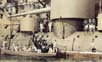
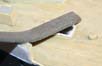
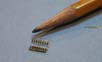
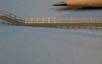
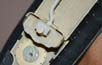
| THE EYEBROWS ABOVE THE PORTHOLES | |
| In 1/350 they are near-scale.( see the photo of the real
thing on te right).
Making eyebrows--a tedious and repetitive task, --yet is that which gives the hull a much more physical feel. I form a spiral of thin copper wire on a suitable size piece of wire The spiral is cut into short spiral segments with a sharp blade. These are then cut through again to form circles. Thereafter these are cut again into just slightly less than semi-circles.One does require a high tedium threshold. |
 |
 |
|
 |
|
 |
|
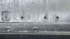
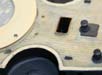
| VENTS, LADDERS AND HATCHES | |
| With the model to be displayed at anchor, I needed to open
up the companionway hatches for the crew to be able to access the inside
of the ship from the spar deck. Much study of plans gave the correct direction
of the stairs.
I removed the top of the cast hatches with a curved rifler file. Then
I drilled down deep and undercut sideways with a mini-motor tool. Thereafter
I made the hatch coaming surrounds with a suitable sized piece of PE from
the spares box.
|
 |
 |
|
 |
|
| The aft staircase which I wanted to show open but discovered too late to drill open as I had done with the others due to its position under the previously installed delicate catwalk. I elected to show the canvas framework and canvas covering--as per a couple of photos this was a success; an ascending sailor disguising the lack of recess in the decking. | 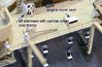 |
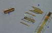
| The various stairs to the levels were giving me some consternation...
B The supplied YS PE in the kit--whilst of fine-line quality in most parts was rather over scale in the stair handrails.... A I chose to use the far more delicate( generic) WEM items, whose treads are also a bit narrower and closer spaced. C When assembled these lacked substance at the sides; real ship photos showing the YS pattern of pierced sides to be correct. D A compromise was reached - utilising the YS side members in conjunction with WEM treads. |
 |
 |
|
| I managed to find two doors and windows in the aft bulkhead that were not shown on the plans, and replaced the open doors to the hullside companionway opening with brass items( WEM Koenig). | 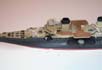 |
 |
|
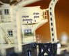
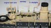
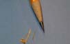
| The engine room vent coverings were made of a curved piece
of paper. The difficulty of cleanly cutting and inserting 2 x quarter-circles
in each one to represent the end panels was beyond my patience....
I applied a piece of thin stretched sprue at each corner, and then in-filled with thinned white glue. When painted this gave a very clean demarcation and a convincing effect. The tiny box shape vent seen on the stb side in real-ship photos was made of styrene rod and paper sides and back--so as to get an open vent. Small square vents were added to the stb side of the funnel- these are not on the plans but can be seen in photos. A small cowl vent was added to the aft deck and a further two on the 100 mm gun deck. |
 |
 |
|
 |
|
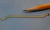
| The making of the four large accommodation/boarding ladders,
two for the officers aft, with a further two among the midship battery
for the crew required some thought. The kit supplied PE extension platforms
appeared to me to be to short in having insufficient reach to clear the
tumblehome.
I made new platforms by joining up some WEM stock grating and Koenig treads and rail parts cobbled together. With copper wire supporting struts underneath upper and lower. Adding all the supporting struts underneath the four companionways( 4 per set = 16 in total ) consisting of thin strips of flat brass cut from PE rigging took over 3 hours to get right ! |
 |
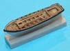
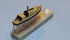
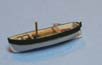
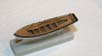
| SHIPS BOATS | |
| Making, detailing and fitting out the numerous ships boats
took a considerable amount of time
I began to enjoy these mini projects--albeit there are rather a lot of them... All the gunwales were thinned down with a sharp blade, the stems sharpened,
and new tillers made.
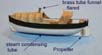
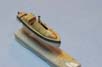
The small 'window' panels in the spray-hoods were made by using white glue to simulate the canvas; as it dries clear the canvas was painted omitting the window area.... The funnels had their distinctive flare induced into the fine brass tube by first drilling the walls and then spreading with a blunt pushpin . The propellers were fine PE item from the kit, which had the pitch
twisted in.
A gentle coat of matt varnish and the addition of the inner coamings
of stretched brown sprue sharpened up these little boats.
|
 |
 |
|
 |
|
 |
|
 |
|
 |
|
 |
|
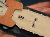
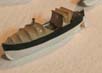
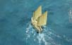
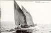
| The boats have been slung outboard--with the shore-excursion
party returning-some officers and men under sail and some officers in steamboats.
The crew-transport gigs although oar powered--appear to al have carried quite substantial lug-rigs -consisting of two unstayed pole masts- supported by a movable tackle on the windward side only. These boats sailed surprisingly well--even when carrying 30 or more
crew!!!!
|
 |
 |
|
| BOAT CRANES | |
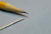
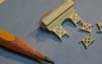
| Meanwhile-- the castings--fine as they are--still need
to be prepared. The davit cranes supporting brackets all had to have the
fine wafer of resin removed-- not difficult--merely arduous due to the
number of apertures that needed clearing.
I used a fine drill bit in a pin-vice for this task. |
 |
 |
|
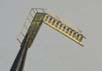
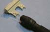
| The cranes themselves after examination of photos appeared to be fitted
with rungs on their outside curve--presumably for personnel to be able
to reach/service the blocks and sheaves. I tried various ways of simulating
these, CA gluing on ladders and trimming off the sides with a sharp knife...--very
regular--but too closely spaced. I tried the same trick with larger 1/200
scale ladder, but it looked too clunky. I also applied stretched
sprue; tedious and alas--due to my ham-fistedness--too irregular.
I resorted to a compromise solution: I marked the rungs in with pencil;
then by drawing a knife blade across the line and lifting I had regular
bumps ....- the overall effect is more subtle than the above method would
suggest!
An interesting feature is that the cranes are of differing heights and
not symmetrically placed on the ships hull Port to Starboard - this needed
to be corrected as the side elevation plan is of the stb side onlyand
the portside crane bases are in considerably different locations.
|
 |
| HANDRAILS EVERWHERE | |
| I added many of the weather deck handrails( with the wooden top rail)
from the YS kit PE fret, all the while trying to ( rationally! ) convince
myself it would look thin and fine enough once painted.... Close examination
of large high res photos however showed that the foredeck and parts of
the aft deck had conventional stanchion and wire railings, with the wooden
handrails extending only partially along the upper decks. So as to create
a sense of uniformity of size, finesse and contrast I needed to utilise
a different railing style for the wire and stanchion rails. I was
fortunate in having previously ordered 3 x WEM Koenig frets, discounted
second quality, damaged /or over-etched. Some of the two bar railings on
this finest of frets which had been over-etched was really very fine indeed
... and when offered up to the previously carefully installed railing made
the previous effort appear somewhat fencelike... As a result I had no choice
but to remove the previously installed and painted Railing. A cunning plan
to ensure finesse and uniformity was devised.
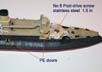
Using the same style of railing from the WEM fret for both stanchion and wooden topped rail.... BUT installing the wooden portions of the rails UPSIDE DOWN--so that the straight waterway would become the wooden top rail, with the cable and stanchion type being installed conventionally. This ensured consistent line thickness throughout and instantly lifted both the model and my spirits! A Discarded Railing B WEM Koenig railing C YS railing
|
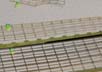 |
| The transition from solid railing stanchion and cable was effective. The time spent on the railings was inordinate; simply because I had to cut-and-shut the railings into many small pieces so as to create un-noticeable reductions in spacing or to get stanchions in the correct places according to photos. Another interesting issue was previously un-noticed gentle sag of approx 0.1.5 mm in the linear for and aft plane of the centre deck... I attached the rails with a droplet of CA under every second stanchion and in-filled the gaps(about the thickness of a sheet of printer paper!) with thinned white glue... | 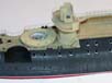 |
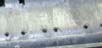
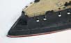
| The finesse of the rails aft can be see to good effect along with the
glazed portholes in the hatch lids.
The longer spaces between the stanchions either side of the mooring bits will have the (removable) sections made of stretched sprue. |
 |
| The long catwalk that interconnects the fwd and aft superstructure
across the main deck was tackled next.
The floor of which is a fine and thin resin casting; alas nothing is ever thin enough for my liking, so attaching the PE handrail to the upper face was always going to be unsatisfactory. The Handrail on the real ship had a wooden taffrail on the top- and this was nicely rendered in the PE. I was worried that when painted this may be over scale-so I turned the PE upside down and utilised the larger PE section as the side member if the catwalk I felt that a generous and judicious application of paint via brush would thicken up the handrail anyhow- and give the desired effect once installed. |
 |
 |
|
| Having trimmed, bent, twisted and forced the catwalk to my satisfaction,
I set to install it and the supporting struts.
The Kit supplied PE was designed for the rails to sit upon the resin floor-- they were now too short. I wanted to retain the slight flare at their bases and searched through my PE stock for something suitable; alighting once again on the L'Arsenal Liberty set. I used some rigging (?) parts... |
 |
| As mentioned before - much effort has been made to ensure the rails and waterway sit flush with the gun-deck edges. the casting being cut away to allow a styrene insert that could be trimmed with a blade. | 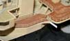 |
| Rails around the upper bridge were pieced together from very short lengths to ensure symmetry and that a stanchion would be on a corner - (where applicable according to photos... ) The interdeck struts were inserted; again alignment was at times a trying past time.... | 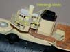 |
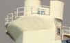
| The aft superstructure had small extensions fitted for
the QF guns (presumably to give a better arc of fire?)
These were NOT shown on the plans... but are readily discernible from photos. They were made by first forming the railings to desired shape-and the infilling the resultant gaps with white glue. |
 |
 |
|
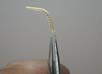
| I also experimented with making the distinctive curved awning frames over the stairwells... Stretched sprue worked best in this instance--an even curve was achieved. |  |
| The rails twixt the turrets were very fiddly--as one or two stanchion bases did not offer a big contact area for glue to adhere-- I ended up tacking with matt varnish that was almost set and backing up with a droplet of CA applied with a piece of stretched sprue. | 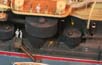 |
| page 2 of 5 |
More
of Jim Baumann's work.
Updated 2010

© ModelWarships.com