photos by Ed McDonald
| THE KIT | |||||||||||||||||||||||||||||||||||||||||||||||||||||||||||||||||||||||||||||||||||||||||||||||||||||||||||||||||||||||||||||||||||||||||||||||||||||||||||||||||||||
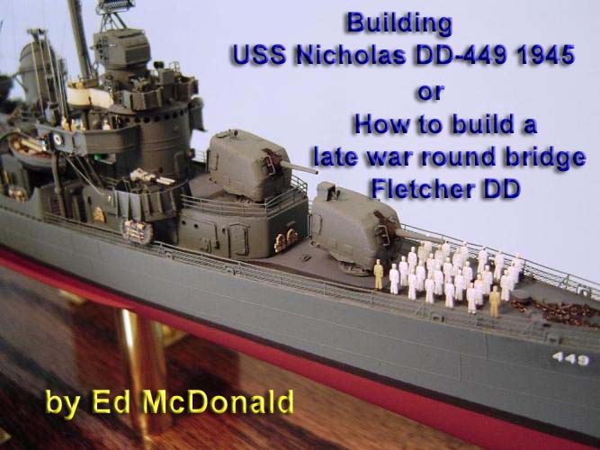
This ship was built from the Tamiya 1/350 round bridge Fletcher Class kit; which is designed to be an early war Fletcher and there are only a small number of ships that it can correctly model. Nicholas was one of those. However, the kit only represents an early war Fletcher class ship, and I intend to model Nicholas as she was in 1945. There are other late war kits available, but they represent square bridge Fletchers. Nicholas was a round bridge Fletcher. Rather than using a late war kit and modifying the bridge, I chose to use the Tamiya early war kit and modify or add the late war improvements.
| |||||||||||||||||||||||||||||||||||||||||||||||||||||||||||||||||||||||||||||||||||||||||||||||||||||||||||||||||||||||||||||||||||||||||||||||||||||||||||||||||||||
| THE APPROACH | |||||||||||||||||||||||||||||||||||||||||||||||||||||||||||||||||||||||||||||||||||||||||||||||||||||||||||||||||||||||||||||||||||||||||||||||||||||||||||||||||||||
This build will require considerable scratch work in order to construct the several various shields, decks, platforms and such that were added to Nicholas during her career. I will only be explaining what to do and will not be spending much time on how to do. And, this is only one of several possible ways to build this model. Other unexplored approaches might be easier or less expensive. If you are aware of one, please let me know. This is just the method I have chosen to try and well see what happens. I will also be adding scratch built detail whenever possible. This model will be detailed to the maximum possibility super detailed, as it is sometimes called. But, this is not required. Its just the way I model things when photos and resources are available. When I talk about scratch built details, feel free to consider them optional if you wish except where those scratch built items are required in order to accomplish the conversion.
| |||||||||||||||||||||||||||||||||||||||||||||||||||||||||||||||||||||||||||||||||||||||||||||||||||||||||||||||||||||||||||||||||||||||||||||||||||||||||||||||||||||
| REQUIRED MATERIALS | |||||||||||||||||||||||||||||||||||||||||||||||||||||||||||||||||||||||||||||||||||||||||||||||||||||||||||||||||||||||||||||||||||||||||||||||||||||||||||||||||||||
| |||||||||||||||||||||||||||||||||||||||||||||||||||||||||||||||||||||||||||||||||||||||||||||||||||||||||||||||||||||||||||||||||||||||||||||||||||||||||||||||||||||
OPTIONAL MATERIALS |
|
ALTERNATIVE APPROACHES |
Many of the required and optional items mentioned above could be obtained (and probably for less money) by bashing a Trumpeter The Sullivans kit. For example, in that kit the 5/38 barrels are properly positioned (however the gun bodies are a bit narrow and include some incorrect detail) and the required number of twin 40mm guns is included (although their detail is poor). Of course many of the needed late war platforms and shields are also included in that late war model and are quite acceptable. However, considerable modification would still be required in order to get those parts to correctly represent the late war Nicholas (which had a fairly unique appearance) and to get those parts to properly fit into the Tamiya model. There was also always the option of using the Trumpeter kit as the starting point and scratch building a round bridge and pilot house. However, the general lack of detail and accuracy in the Trumpeter kit discouraged me from using that approach. Another possible approach would be to use Toms Model Works square bridge conversion kit. Its designed to alter the Tamiya early war round bridge kit to a late war square bridge model. Although, in this case, the square bridge parts would not be used only the late war platforms and gun tubs. But, again, Nicholas was a bit unique and some parts might not be quite correct.
THE MODELED FOR DATE |
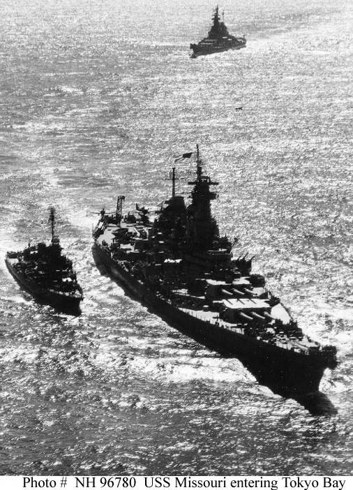
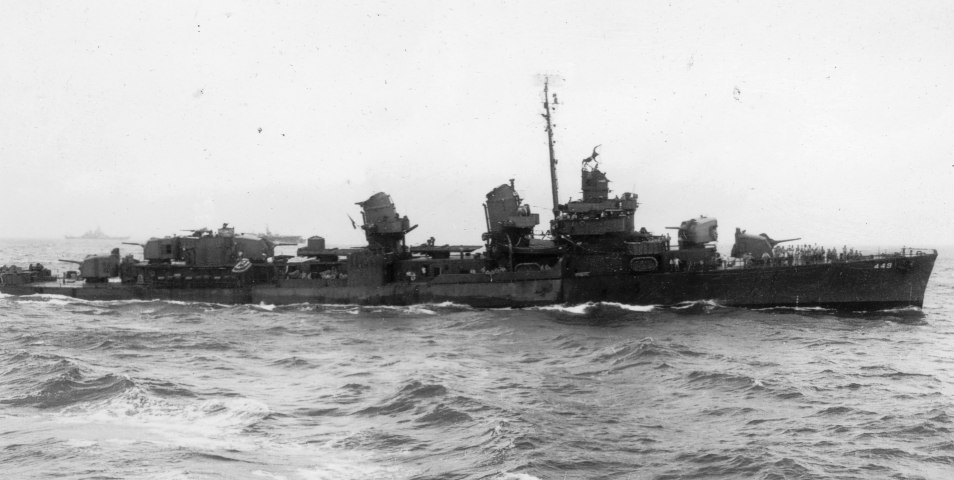
This model will be designed to represent Nicholas as she appeared on the morning of 2 September 1945 at the Yokohama Customs House Pier where she embarked 87 Allied representatives for transport to the USS Missouri for the Japanese surrender ceremony. There are many photos of Nicholas on that day and on the preceding several days as she entered Sagami Wan and escorted Missouri into Tokyo Bay. There are also several excellent photos of Nicholas during and just after her early 1944 refit at Mare Island. Nicholas was certainly one of the most significant American destroyers in history. She earned 16 battle stars and a Presidential Citation in World War Two and went on to win 5 battle stars in Korea and 9 in Vietnam. She also served in the recovery operations of Apollo 7 and 8. Her selection as the escort for USS Missouri, in the van of the battle line, when entering Tokyo Bay on 29 August 1945 indicates how highly she was regarded. Additional information and photos may be found at DANFS History, NavSource Photo Archives and at the USS Nicholas Home Page.
STEP 1 - THE HULL |
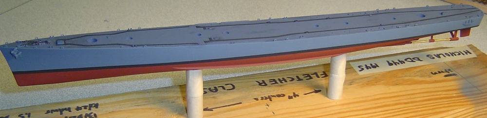
Build the hull, shafts, struts and rudder as instructed. I chose to ignore the hinged rudder; which doesnt fit quite right and flops around, and just glue it together instead. The ship was painted in MS21. I chose to mix a slightly lighter than normal Navy Blue so that detail would still be at least somewhat visible. Additionally, there was a world wide shortage of indigo pigment in late WW2 and blue paint was stretched by mixing it with available gray shades. I used the Eduard screw guards (somewhat higher detail). I resisted an inclination to attempt to drill out the shaft supports and use brass rod for the shafts. Instead, the plastic shafts were painted with several coats Model Master Brass.
STEP 1 - THE MAIN DECK |
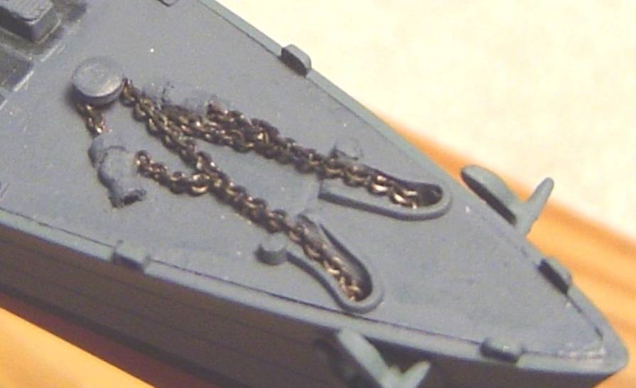
While waiting for coats of paint on the hull to dry, I worked on the main deck. There are several things to be done here. First, I intended to use real chain for the anchors. That means that the molded in chain, as well as several other molded in items, needed to be removed. A dremel with a fine grinding tip, followed by some light filing and sanding works well enough. Holes were drilled for the chain in the chain well covers and forward in the chain channels. The now damaged chain well covers were removed and replaced with short pieces of half moon cut 1/16 plastic rod that was drilled out to about 3/64. I put a cover piece on the otherwise rather incorrect looking capstan. The chain channels were filed down a bit with a round file to be certain there would be room for the chain under the safety grates which were to be installed later. Last, several PE hatches from both Eduard and GMM were installed and two molded-in hatches just aft of gun 55, which appear in no photos or plans that I have, were removed. Paint the deck Deck Blue. Then I masked the non-skip strips and painted them with a special mix of very dark blue (almost black) that looked just like I recall non-skid from my years in the Navy. These were solid on Nicholas rather than broken into segments (as represented on some decals) as was the case on many other destroyers. Next is the anchor chain. Im using A-Line pre-blackened #29219 40 links per inch chain. I was unable to actually open and link the tie down chains together (just too small for me) and resorted to using bits of twisted 32 gauge wire to make the connections. The chains were then threaded through the prepared holes in the deck and glued to the underside of the deck. The last step is to mount the assembled and completed hull and main deck onto a temporary working base. Here's the hull and main deck assembled and mounted on a temporary working base and a detail of the anchor chains.
STEP 3 - DETERMINE THE TOPSIDE 1945 CONFIGURATION |
Luckily, Nicholas is fairly well documented. Actually she never carried a late war outfit. Her last overhaul ended in January 1944 and thus, she ended the war with a mid-war outfit. In that overhaul the following changes were made
|
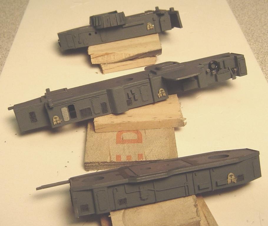
STEP 4 - THE FORWARD DECKHOUSE |
As always, the first step is to remove those items that we dont want. The following list itemizes what to remove by part number:
|
The following new parts must be made
|
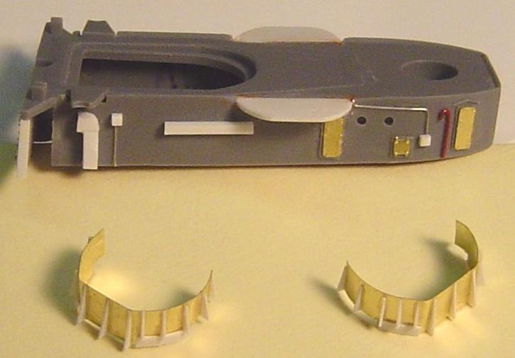
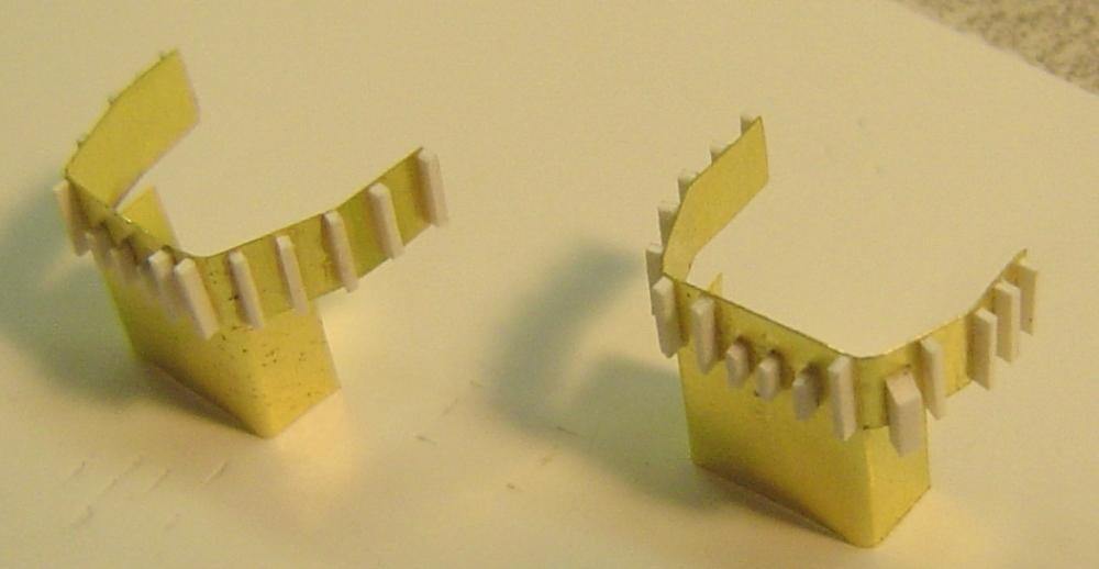
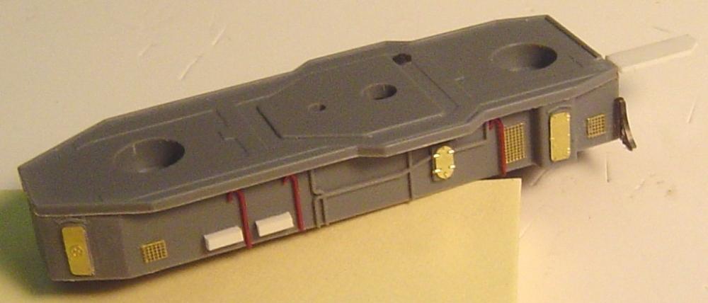
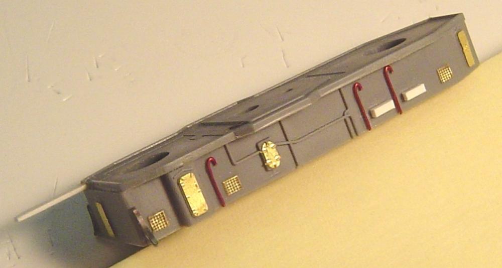
Next, the parts are assembled and the gaps puttied. After a good sanding on the puttied areas the missing portholes are drilled and the PE details are added. I have chosen to remove the fire hose racks on the forward bulkhead because I intend to replace them later with GMM PE fire hose racks. I have also chosen to add various details to the bulkheads made of fine wire and styrene. If you want the spray shields to fit just right, you will also want to add a couple of .020 x .040 styrene strips at the points where the PE spray shields meet the aft bulkheads. The new 40mm shields are made from thin brass sheet and enhanced with bits and pieces of styrene. Here's the a starboard view of the forward deckhouse detailed and ready for painting.
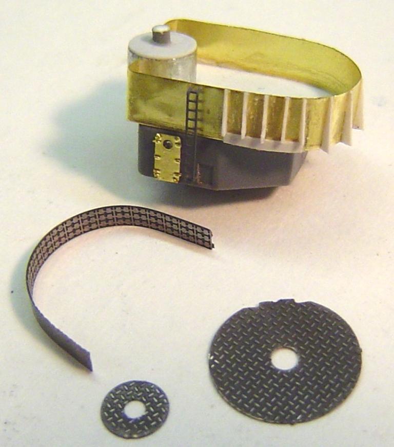
STEP 5 - THE AMIDSHIPS DECKHOUSE - 1 level bulkheads and 01 deck |
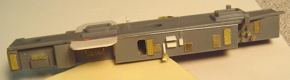
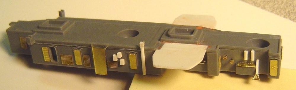
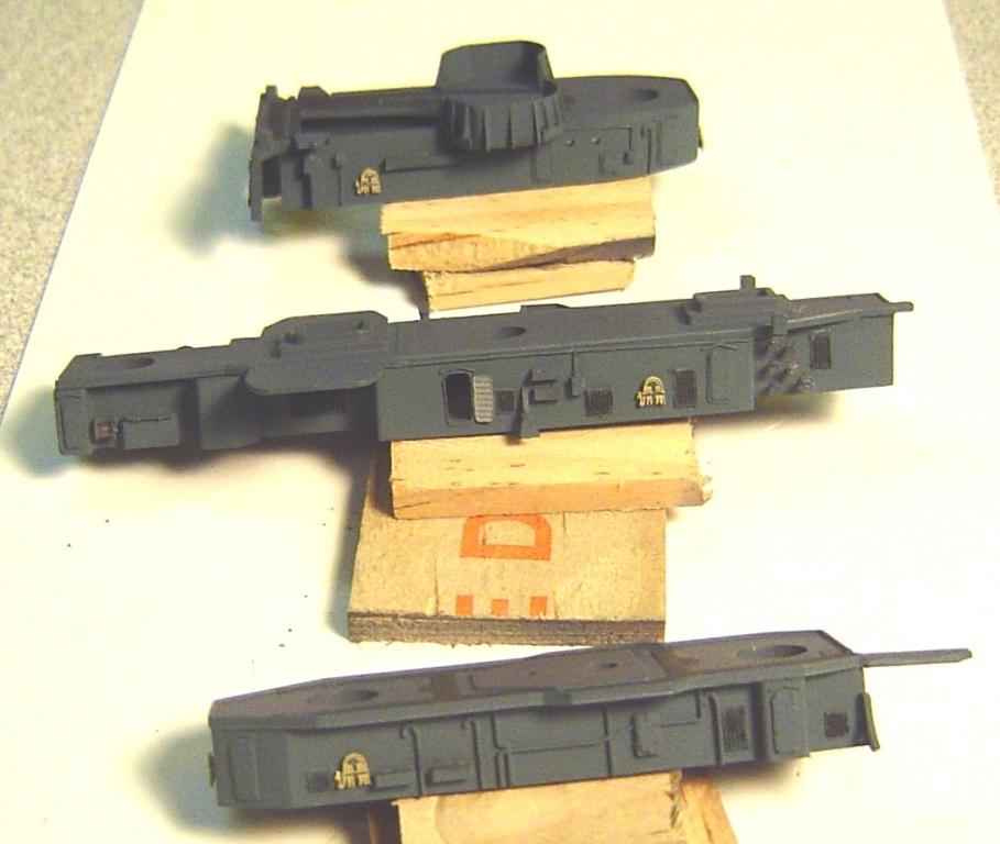
There is only one item to possibly remove from this unit. If you intend to use Eduard PE part 8 (the matted deck effect for the amidships 01 deck) then you will need to file a small slot in the lip around the deck far aft where the deck connects by catwalk to the after deck. Test fit Eduard part 8 until you get it right. The major work here is the addition of the amidships 40mm gun tubs and support structures. In 1945 Nicholas had dual 40mm guns here. As with the forward 40mm tubs, a scaled top down plan view of a late war Fletcher can be used as a template to cut the platforms from styrene. Well almost. If you study the photos of Nicholas after her 1944 refit (where these guns were added) you will discover that the shape of the tubs was not quite standard and did not conform to the normal late war design. But, actually that makes it easier since the standard design involves a rounded tub (much like those forward), but Nicholas actually had almost square tubs with just a slight angle on the sides. Cut the platforms and then cut again several times to make the inside edges match the shapes of the 01 level amidships deck as molded into the kit parts. The platforms are located alongside the aft stack. Dont get confused by the plans of some late-war Fletchers that had quad (not dual) 40mm guns mounted somewhat forward of the aft stack. Add the platforms level with the deck, file off the lips that surround the deck at the points where the platforms attach and, by the way, putty fill the mounting hole for the torpedo crane on the starboard side. That crane will be relocated later. Putty the assembly as required. The support structure and shields for these two platforms were made from thin brass sheets, cut and bent to fit. It took a couple of hours and 3 tries to get it right but its mostly a job of measuring (use a good quality metal 1/64 inch ruler) and draw up a plan. Once thats done well, its possible to make the support and the shields from a single piece of brass. Then add the styrene outside braces. I chose to open 2 doors on the amidships bulkheads. Then add the photoetch. I used the always superior GMM doors. Be sure the hinges are always on the forward side. I used some GMM floater net basket PE to make the vents. Search the photos and you will find lots of other detail that can be added to the bulkheads. For now, postpone the addition of things that will not be painted Navy Blue and things such as ladders that cant be added until after the assembly is attached to the rest of the model. In the process of testing the fit of the 40mm support structures I discovered that the amidships bits were in the way and had to be removed from the main deck. I have yet to discover if they were moved elsewhere. It also became evident that the two 20mm guns on each side were going to end up being mounted a bit forward of the kits expected location. Doubts about the correct location of the K-guns have also come up. So, you see, this report is being made in real-time. This is reality modeling. As I discover problems, so do you. That nicely painted main deck is going to end up with some putty filled holes and probably scratches here and there. Oh well, people walk on decks and push things across them and they always need work. Next time, Ill know in advance. Last, the photoetch and numerous other details were added. There are not that many close up photos of Nicholas. But there are many of Fletchers and they offer a wealth of opportunity for additional detail. Here's starboard and port views of the amidships deckhouse detailed and ready for painting and a photo of the new 40mm shields.
STEP 6 - THE AFTER DECKHOUSE |
Remove the molded on ladders and assemble and putty the four parts. Additionally, if you are using Eduard part 8 (that amidships matted deck effect) then you will at least need to file off the lips on the forward catwalk and open the lips on the deck just a bit. The Eduard instructions recommend removal of the molded-in catwalk. I have chosen to do that and scratch build a new one from sheet styrene to match the shape of the catwalk on the PE. However, the differences are quite minor and you can probably get away with the use of the molded-in one if you just file off the lips. Then add the PE and detail that can be discovered in the numerous available photos of Fletcher class DDs. Here's starboard and port views of the after deckhouse detailed and ready for painting.
STEP 7 - PAINT THE DECKHOUSES |
Airbrush Deck Blue on the tops of the three deckhouse assemblies and on the Eduard PE part 8, if you are using it. Dont worry about some overspray onto the deckhouse sides. In fact, I intentionally sprayed one coat of Deck Blue on the sides to sort of prime those pesky photoetch parts that usually need an extra coat to get a good cover. Next mask the non skid paths on the forward and aft 01 level decks and airbrush the Non-Skid color. If you are not using Eduard part 8, then you should also mask and paint the non-skip on the amidships deckhouse top. Next, carefully mask the deck tops and spray the deckhouse sides and the insides and outsides of the four 40mm tubs with Navy Blue. Next, I brush paint the bottoms of any overhanging platforms (in this case the 40mm platforms and catwalks) with Light Gray. I have no photos to verify this, but from my US Navy experience I can say that otherwise dark passage overheads were always painted light gray or white. Last, any vertical parts (the boat davit attachment points) should be brush painted Navy Blue. Now is the time to paint and add the remaining details such as fire hose racks and bulkhead mounted cable reels. It also looks good if you paint the vent screens with a dark gray or black wash. Paint the insides of the open doors light gray or white. You can now go ahead and glue the two forward 40mm tub shields to the forward deckhouse. But Im going to wait a bit on the amidships tubs until Im sure Im ready to attach the amidships deckhouse to the main deck. The finished deckhouses starboard and port views
STEP 8 - THE AFT 40mm PLATFORM |
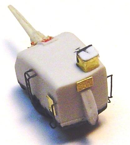
The aft 40mm platform (between guns 52 and 53) that is included in the kit is a very early war version. Due to top-heaviness in the early Fletchers, by 1943 it was cut down and replaced with a considerably lower version. The 40mm tub was quite different from the early version, the MK51 director tub was relocated and the entire platform was several feet lower. At first glance it appears that simply cutting off the second level from the support assembly (parts B3 and B4) would result in a considerably too short deck level. But, it seems to have been that way. If you carefully measure photos and plans it seems that this unit was about 75% of the height of the main deck bulkheads. And, in fact, the lower half of parts B3 and B4 is about 75% of the height of the kits main deck bulkheads. So, carefully cut off the upper part of the B3 & B4 assembly and file it smooth. Dont worry about how it looks. The entire top of the assembly will be covered by the next part you make. That part is the base for the 40mm tub. There is a curious tear drop shaped extra part in this kit, part B6, which is not used in the instructions. It is, in fact, the correct shape for one of the various late war styles of 40mm tubs used in this location on some ships. Perhaps it is the right shape for Fletchers late war 40mm tub. I have not investigated that. But, its a moot point since it is quite clear from photos of Nicholas after her 1944 refit that it is not correct for Nicholas. She had a fairly common U shaped tub, much like those often used on top of the 16 guns on battleships. I do have some spares of those and am tempted to use one. But, I said I would be scratch-building the required parts, so for those of you that dont have a spare tub, here goes. Find a scaled top view plan of any Fletcher that shows the U shaped 40mm tub at this location. Cut some .020 sheet styrene to match its base shape. It should be just very slightly thinner (by twice the thickness of the brass sheet you will use to create the shields) than the width of the B3 & B4 assembly. There is very little extra room here and this part will be a tight fit between the 5 inch guns. Keep the new parts as small as possible. One-quarter inch tube (I like aluminum tubing because its so easy to cut and file, but you may prefer brass) always makes excellent 1/350 scale MK51 tubs. That tub was unusual on Nicholas. It more closely resembled the style of the mid war built Fletchers. In that design there really was no tub at all. Rather, the original early war tub had a top added to it and functioned as a platform for the MK51 which was surrounded by a railing, rather than a shield. The MK51 itself was supported by a short post. Photos of the assembly should make this clear. Cut some thin brass to make the shield for the 40MM gun. Add the braces and supports made from .010 styrene. Add the PE (doors and ladders). Im going to airbrush Eduard parts #12 and #61 (matted decking) and part #51 (ammo racks) separately before I add them to the assembly. The aft 40mm tub and detail PE ready for painting
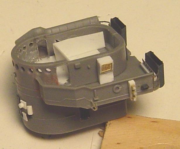
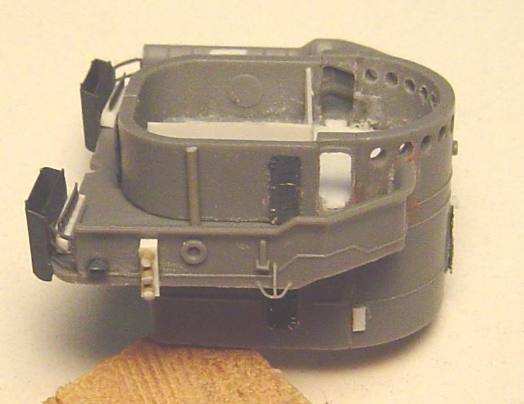
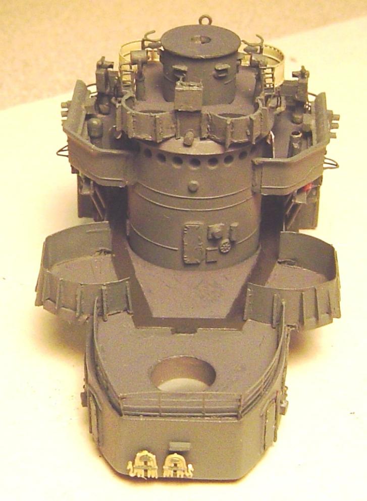
STEP 9 - THE BRIDGE |
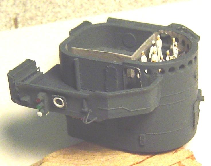
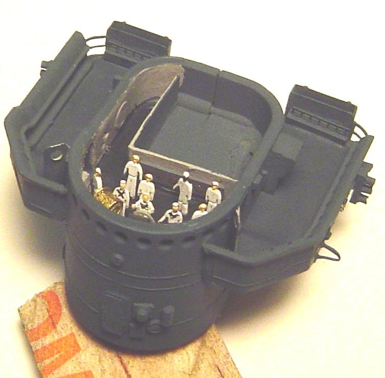
Since Im building a round bridge ship from a round bridge kit one would think that no modifications are needed here. Not quite so. The mid war addition of the forward 40mm guns also added two MK51 directors and shields on top of the bridge. But that will come later. First we will build the bridge itself. Assemble parts B8, B9 and B15. Putty and file as required. Drill out the bridge portholes. I chose to open the two bridge doors. Most photos show them open, and officers really dont care much for dogging and un-dogging doors. Plus, these were frequently used doors. This is all optional, by the way. Well if those doors are open, that means that we need a deck inside the bridge or else anyone walking through would fall down one level. Cut a thin piece of sheet styrene to fit inside the bridge assembly, so that it fits level with the opened doors. It took me two tries to get it right. Well, as long as there is now a bridge deck, lets do just a little more and get the interior of the bridge right. Two simple styrene bulkheads solve that problem (make sure they are not so high that the bridge overhead doesnt fit). Its really not very important that it all look great because no one will be able to see it anyway. Its just something there in case someone peeks in one of the open doors. Plus, now that there is a deck, I can add a few sailors inside the bridge (always a nice touch). I found a few photos of a Fletcher class bridge online. Its pretty basic with a helm in the center, engine order telegraph just to starboard and some assorted other stuff around. The deck (in those photos at least) appeared to be non-skid. The bulkheads were light gray and the equipment appeared to be ocean gray. But those details and brush painting will come after the bridge assembly is done. So leave the top (part B16) off for now. Besides it needs some modification for the Mk51 tubs anyway. Add the wing platform (part B14) and putty the gaps between its forward edges and the bridge body. This is unfortunate. Its the very first parts fit problem Ive seen in this kit. If it were not for this issue, the bridge wings could be painted separately before assembly and everything could be airbrushed. Because of the need for that putty work, it looks like the bridge wing decks will need to be brush painted. Now add the photoetch and other detail that can be found in photos. Next, add the bridge wing shields and do another small putty fill along their forward edges where the shields meet the bridge body. Bend and add the flag bags and other items from the Eduard PE. If you search photos youll find several other details that can be added. I cant believe they left the flag bags and fighting lights out of this otherwise excellent kit. But, thats not all that unusual. Last Ill add some pin rails in front of the flag bags. Well, they actually wont be 1/350 scale belaying pin rails. I tried that once and they were just way too small to tie off on. So, I use a strip of styrene with a short section of narrow ladder PE firmly glued to the top. That gives me a place to tie off the signal flag halyards without too much difficulty. Here's starboard and port views of the bridge before and after painting
STEP 10 - THE BRIDGE 03 LEVEL (PILOT HOUSE TOP) |
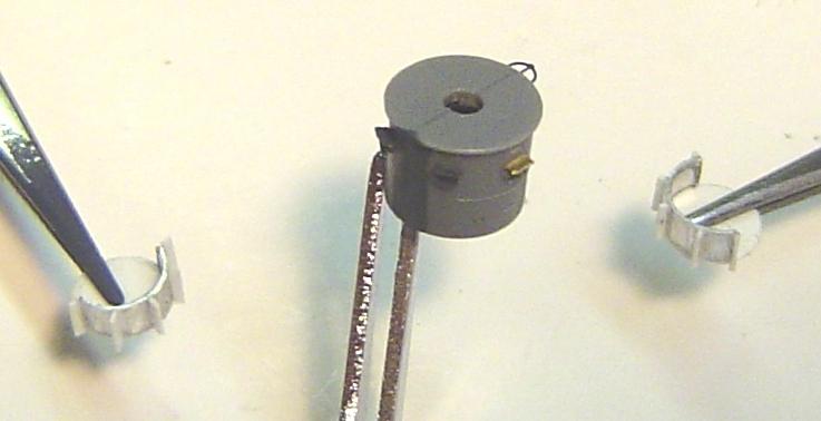
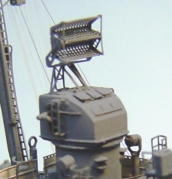
Theres really only one significant change here. Two Mk51 tubs need to be added forward on the 03 level. They are actually half-tubs. Use that old reliable ¼ aluminum tubing cut to the height of 1/350 railing, cut it in half, add some styrene bottoms and some styrene outside braces and its done. In some distant photos of Nicholas it appears that she had shields all the way around the 03 level. But look at ALL the photos of her in 1945 and you will see that sometimes she had railings there. How is that possible? Well, they were always railings, just most often covered with canvas wind breaks. There is an excellent photo of this area on the Nicholas website (via the Tin Can Sailors site). The tubs were steel but the rest of the deck was surrounded with canvas covered railings. Next I detailed the base for the MK37 director. Im going to wait and do the MK37 itself almost last. Their radars seem to be a serious finger trip point and if added early, they always get broken. Here are the tubs and MK37 base ready for painting
Im going to paint all these parts separately before assembly. Ill paint the underside of the 03 deck Light Gray and airbrush the topside Deck Blue. The other three parts will be sprayed Navy Blue and, just for a contrast, Ill paint the floors of the MK51 tubs Non-Skid. The overhanging edge of the MK51 tubs will be Light Gray. After its all painted and assembled, Ill add the canvas covered railings (GMM generic railings PE set).
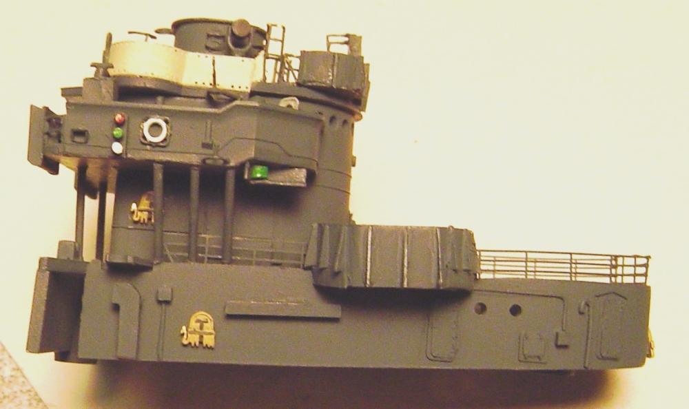
STEP 11 - DETAILS AND COMPLETION OF THE FORWARD DECKHOUSE ASSEMBLY |
As with any ship, there are a lot of detail instruments scattered around the bridge and signal bridges. The previously mentioned photo of the bridge taken during Nicholas 1944 overhaul (posted on the USS Nicholas website) is the best source for information here. Generally speaking, it is much easier to make and add these sort of parts before everything is assembled, while you still have easy access to decks and such. That photo shows that the bridge wings (02 level) had the following instruments:
|
| The photo also shows a number of instruments on the 03 level (bridge top).
|
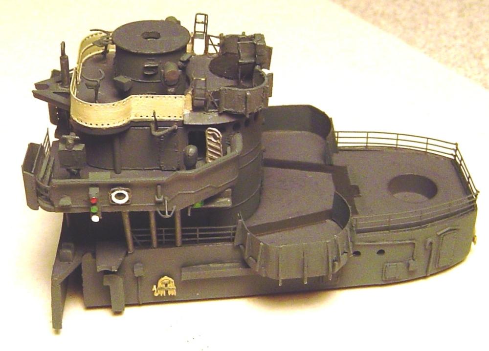
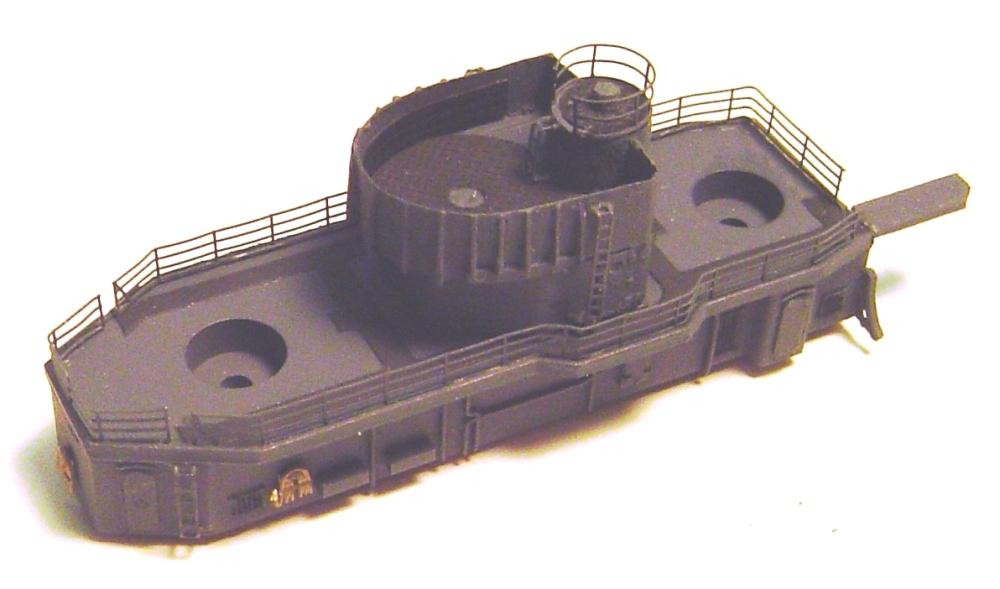
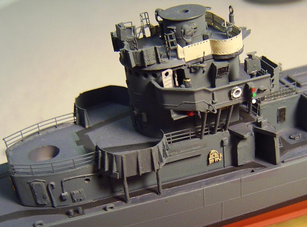
| After all the above parts are made, painted and added, you will have three assemblies forward deck house, bridge and pilot house top (03 level) and now its time to put them together. But first, there are some support posts needed between the 01 level and the bridge wings. Make these posts from some .025 styrene rod cut to eight lengths of 11/32 each. Two go under the aft end of the bridge wings and the other six (three per side) angle from the bridge wing outside edges to the edge of the 01 deck. Add the 01 level railings (leave room for ladders) and add the 03 level assembly and the forward deck house is finished. Here's the completed forward deckhouse
STEP 12 - COMPLETION OF THE AFTER DECKHOUSE ASSEMBLY |
There isnt very much left to do on the after deckhouse. However, there is one question that needs to be answered. The original design for the Fletchers included one torpedo handling crane, mounted amidships, that served both sets of tubes. But, the mid-war addition of the 40mm tubs amidships made that impossible. So, two cranes were added one forward and one aft. The forward crane seems to have always been mounted starboard. But the location of the aft crane varied depending on the ship. On some Fletchers the aft crane was mounted portside on the forward corner of the aft deckhouse. On others it was mounted starboard on the outboard edge of the catwalk between the aft and amidships deckhouses. Based on photos of the aft portside of Nicholas that show no crane there, it appears that it was mounted on the starboard side. Thus, since that mounting must be made after the addition of the Eduard amidships deck matting, no modifications to the after deckhouse are needed now. All that is needed to complete the aft deckhouse is to attach the aft 40mm tub assembly, add the 02 deck railing, two vertical ladders aft and the railing around the MK51 platform. You may have noticed that due to their fragility, Im leaving all armament (5 guns, 40mm guns, 20mm guns, Mk51 and Mk37 directors) for last. Here's the finished aft deckhouse (excluding guns). The forward catwalk rails will come later.
STEP 13 - ADDING THE DECKHOUSES |
It might seem that the completion of the amidships deckhouse would be next. But, its essentially as complete as it can be at this time. There are several items to be dealt with such as missing mushroom vents, ladders, railings and such. But these items need to be added AFTER the addition of the Eduard PE matted deck surface; which should be added AFTER the forward and aft deckhouses. In other words, the sequence will be 1) addition of all three deckhouses as they are now 2) addition of the matted deck surface 3) addition of the remaining amidships deckhouse detail. But before we can even get to those three steps, there are some odds and ends to deal with.
|
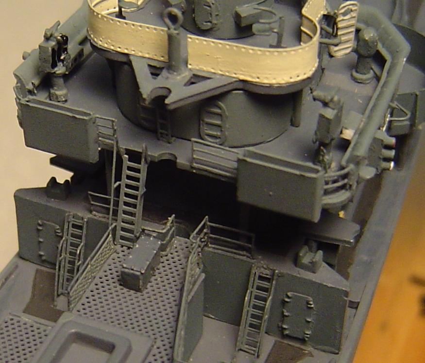
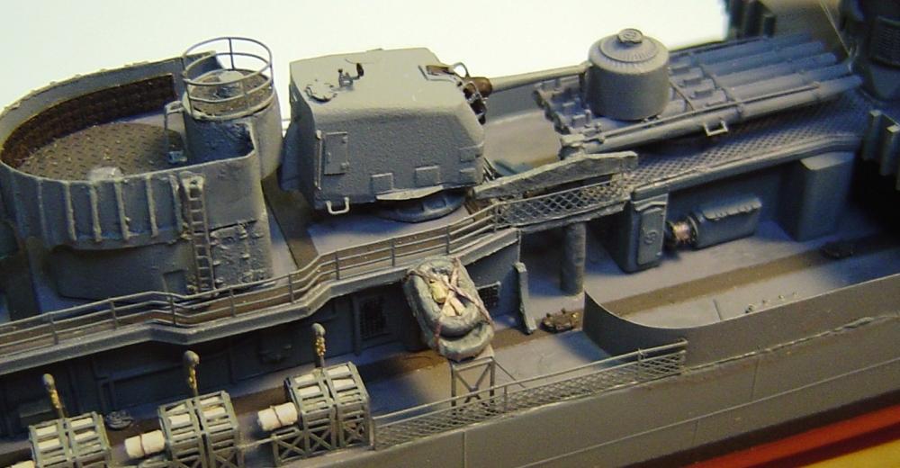
| Now we can add the deckhouses. The forward deckhouse is first and dont forget the two support posts per side under the forward 40mm tubs. Then add the amidships deckhouse and the two amidships 40mm tub shields and support structures. Then the aft deckhouse is last, along with the aft torpedo crane support under the catwalk. Slip the 5 practice loader into the space between the amidships and aft deckhouses. Next add the inclined ladders and rails on the aft end of the forward deck house, between the 1 and 01 decks and the amidships 01 and forward 02 decks. I was not all that thrilled with any of the PE inclined ladders from either the Eduard or GMM sets. I used them, but regret not using inclined ladders from the standard GMM generic ladder PE set. In the future, I believe I will use those instead. I also added a small scratch built equipment box next to the upper ladder. Last, add the rails to the catwalk between the aft and amidships deckhouse and add the aft torpedo handling crane. Here's photos of the deckhouses in place, forward and amidships 40mm tubs and supports, ladders and rails, aft torpedo crane and 5" practice loader.
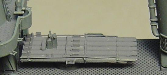
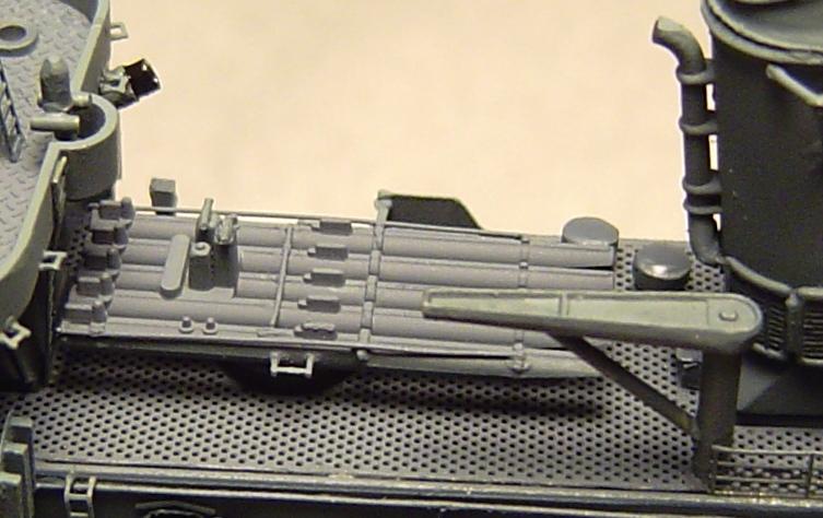
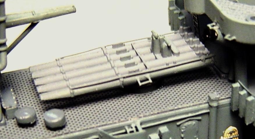
STEP 14 - THE TORPEDO TUBES |
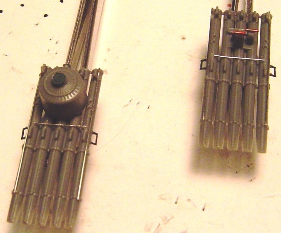
The torpedo tubes provided in the kit are actually pretty decent with some nice detail. But, I did decide to add just a few enhancements 1) wires along the sides that look like they could have been hand rails 2) a wire across the middle that looks like another rail or brace of some sort 3) a couple of wire pieces along the sides that look like step ups 4) a couple of pieces of wire to enhance the poor quality torpedo course indicators and 5) the Eduard suggested PE on the dog house on the aft tubes. I considered using the Eduard PE folding front extensions but since I intended to show them in the closed position anyway, I didnt see any advantage, only difficulty, in using them. Here are the torpedo tubes ready for painting
I airbrushed them with Deck Blue, brush painted the sides of the tubes and of the dog house Navy Blue and painted the exposed ends of the actual torpedoes Dark Gray. A word of caution the mounting bases for the tube units are a tight fit in their mounting holes on the amidships deck house. Be sure they are seated all the way in.
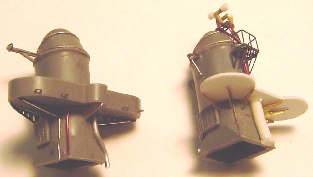
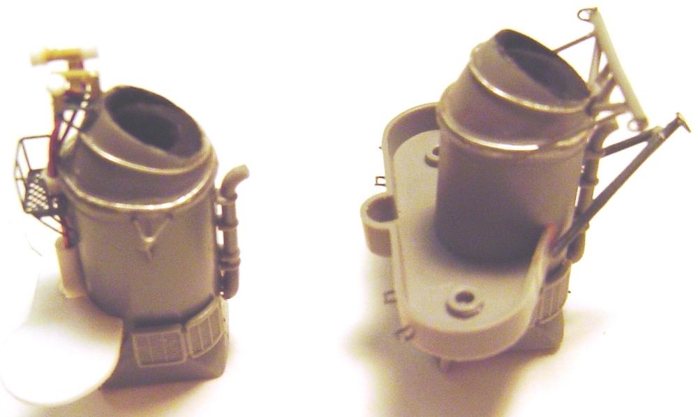
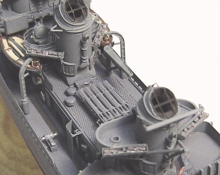
STEP 15 - THE STACKS |
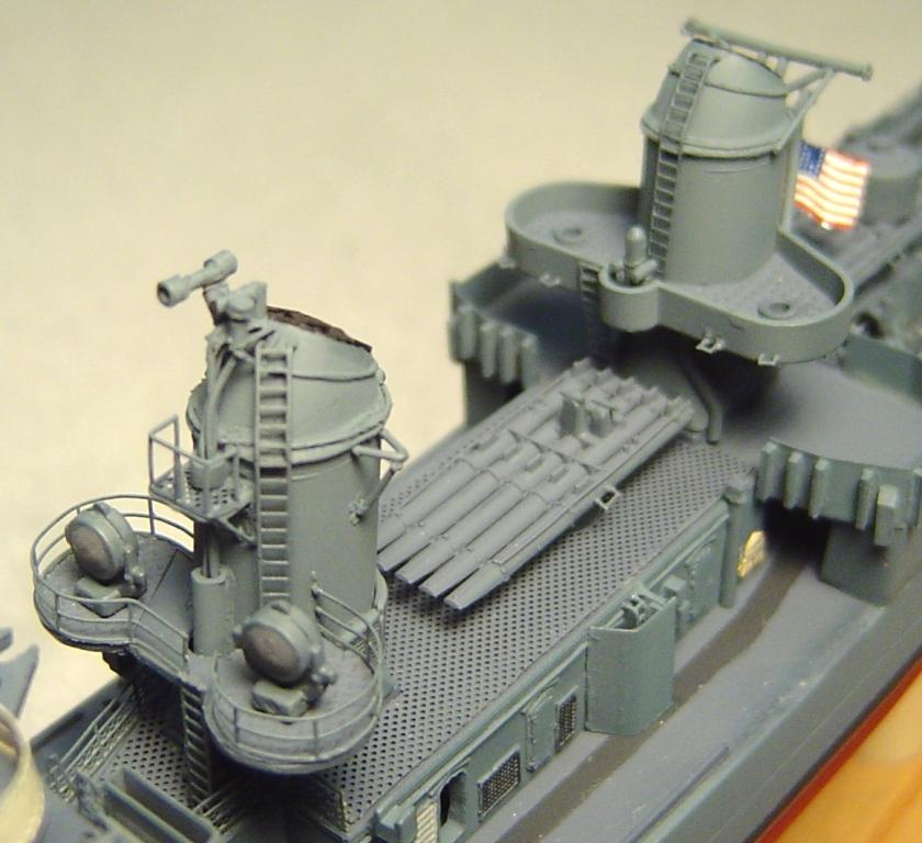
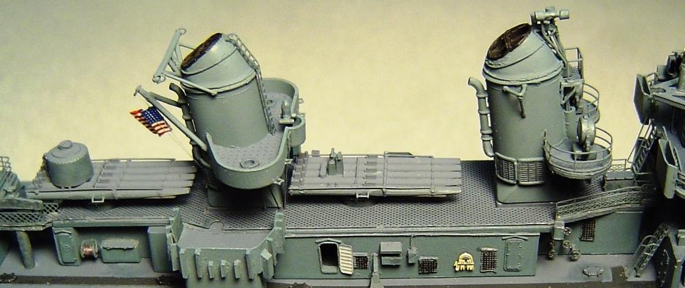
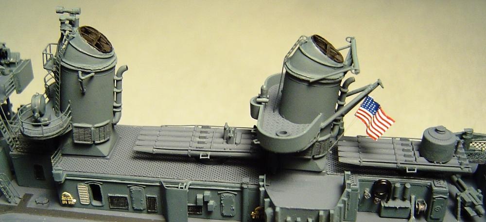
There is room for a good deal of work here. It depends on how detailed you wish to get. The fact is that the human eye is drawn to areas of greatest contrast and in an MS21 ship like this, with very low contrast everywhere, that tends to be the black versus blue on the stack caps. Therefore, Im going to highly detail the stacks. The aft stack and its platform remained unchanged after Nicholas 1944 refit except that the 36 searchlights there were replaced by MK51 directors. The ships compass was still mounted forward in the middle of this platform. But the stack and platform themselves were unchanged. The forward stack, on the other hand, had a new platform, quite different from the aft one, added to its forward side and the 36 searchlights were relocated there. So thats going to be a scratch build process. The rest of the work just depends on how much quality and detail you want. Im going to shoot for pretty high quality and detail so Ill start by hollowing out the stack caps in preparation for the use of the slightly better quality Eduard stack cap PE. After thats done Ill assemble the three main parts of each stack (sides and cap) and sand and file and putty and sand and file until the joints of the parts are nice and smooth. The stack parts dont fit quite as well as have some other parts in this kit. The aft stack platform is a very tight fit that will be difficult to deal with once everything is painted and detailed. So, Ill spend some time filing it for an easy fit. The forward platform is made from styrene sheet cut to match the shape of that platform in any scaled top down plan view of a late war Fletcher. Hint Eduard PE part number 5 provides a good template for the inside (against the stack) shape of the forward stack platform. Note that the new forward platform is surrounded by railing while the aft platform still had its surrounding shields. Some ships had canvas covered rails on the aft platform. But the photos of Nicholas convinced me it was shielding rather than canvas. Also note that you should make a small rectangular cutout in the new forward stack platform for clearance for the various pipes and wires yet to be added to the forward stack. After the putty is sanded and looks good, I added the platforms to both stacks and a bit more putty at the points of the gaps. Once that looks good, add the support braces (Eduard PE parts 65) to the aft stack platform and scratch make similar braces from thin styrene or brass for use on the forward stack platform (I confess that I used some bulkhead mounted crane PE left over from a recent battleship model which, by amazing coincidence, fit quite well). Add the stack vents from the kit. Caution be sure the orientation is correct with the slightly curved part of the vent pointing aft. Now its time to get carried away and add all those wires, tubes and pipes indicated by the photos and mentioned in the GMM photoetch instructions. There are some excellent photos of the forward side of the aft stack and the upper portion of the forward side of the forward stack on Nicholas. Use them as a reference for the pipes, wires and ladders. Add the small platforms and rails from the GMM and Eduard PE to the forward stack. I added conduits for the pipes and wires, as shown in the photos. Add scratch built ships horn, siren and whistle to the upper forward platform. Add the gaff to the aft stack. Add the antenna yards, all antenna wire attachment structures to the stacks and all other detail that can be found (except the stack cap PE and the ladders). Note that if you research photos you will find that there are also a few pipes and wires on the aft stack. Here are the stacks ready for painting
Airbrush the stacks Navy Blue and paint the platform decks Deck Blue. Add Eduard PE part 5 (painted Deck Blue) to the aft stack platform. I chose to add the left over Eduard parts 59 and 60 to the forward platform. Add the railing and the 36 searchlights from the kit to the forward platform. Paint the stack insides Flat Black and add the Eduard PE parts 6 and 7 (stack cap parts previously airbrushed Flat Black). I chose the slightly better (although considerably more difficult) Eduard stack cap PE over the perfectly acceptable GMM version. Add the upper ladders (platforms to stack cap) and paint the stack side vents with a very light black wash. I also chose to add the ensign on its halyard to the aft stack gaff before adding the stack to the model. It was just much easier to access. The Tamiya kit includes a 50 star version of the flag. Why, oh why, do they always do that? Do they not realize in Japan that there were only 48 states in 1945? This is the first error that any knowledgeable modeler will look for. But, with luck, I still had a few 48 star flag decals from a GMM flag decal set that I bought some time ago. Add the stacks to the model and add the ladders from the 01 level upward to the platforms. Add a scratch built ships magnetic compass to the forward center tub on the aft stack platform. Compasses are never included in any kit I have seen, but they are fairly easy to build from styrene rod. You may have noticed that so far the floater net baskets have been ignored. Thats okay theyll come along soon. One note of complaint (well 3 actually if you count the 50 star flag) there is a need for a significant length of wide ladder for use on the stacks. Photos of not only Nicholas but many other Fletchers show wide ladders in several locations. The Eduard PE set includes NONE. The GMM set only includes one short insufficient length. I had to resort to some generic GMM ladder PE. The other issue is 3 bar railing (3 counting the artificial PE bottom rail in other words railing that exhibits as 2 bar appearance) there is NEVER enough in any kit. Again, in order to complete the rails on the forward stack platform, I had to go to a GMM generic railing set. Meanwhile, there is ALWAYS far more 4 bar railing in every kit than is needed. And one more issue (ie. complaint). In this Tamiya kit (which otherwise has been excellent) there is something wrong with the location of the forward torpedo tube. It actually appears to be as much as 1/16 too far aft! Despite numerous test fittings, I didnt actually notice the problem until after the aft stack was installed and I went to add the ladder from the 01 deck to aft stack platform and it didnt fit because the forward torpedo tubes were in the way. The only solution I could come up with at this late hour was to slightly bend the ladder in order to clear the torpedo tubes. Ill need to study this a bit more but, for future work, it appears that the mounting for the forward torpedo tubes should be relocated a bit forward from the kits location. Here's several views of the completed stacks. The last shows the trouble with the ladder to the aft stack platform.
STEP 16 - OTHER AMIDSHIPS 01 LEVEL DETAIL |
There are just a few more things to be done on the amidships deckhouse.
|
| Here's starboard and port views of the forward torpedo handling crane, mushroom vents and antenna insulator.
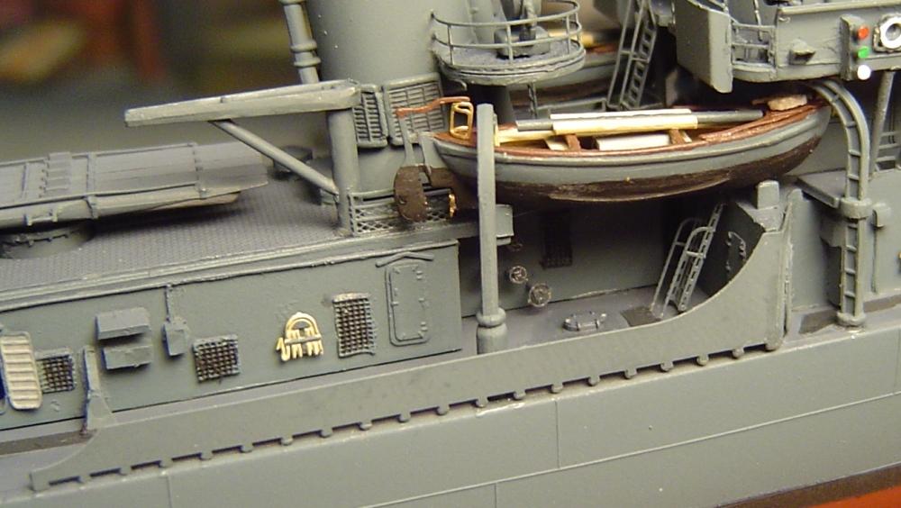
STEP 17 - THE WHALE BOATS, DAVITS AND STUFF |
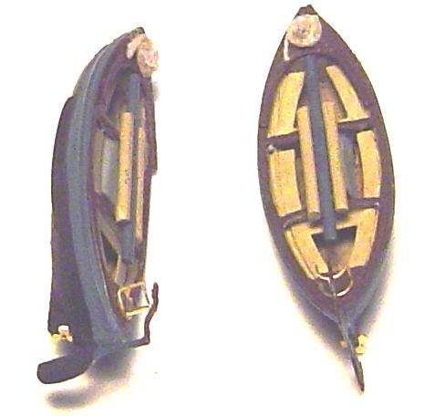
As previously mentioned Ill be using the LArsenal whaleboats. There is really nothing wrong with the kits whaleboats; particularly so after enhancement with the GMM PE. But, Ive been looking for a chance to try the LArsenal boats and at first evaluation, they look great. The davits in the kit have one small problem of a mold hole (whatever those things are for I dont know) on the side of the aft davits. I putty filled them. Those are the first in this kit so far. Also, the forward davits are a poor fit in their mounting holes. You will want file them just a touch (they should be offset 45 degrees from square) until they fit easily and correctly. They are a tight and crowded fit no matter what you do so do all you can to make it easy. Now, how should the boats be painted? Thats always a tough question since there are very few photos of the insides of a WW2 whaleboat and those few are in fuzzy black and white. I usually use some shade of dark brown or red-brown for the wood parts or even just go with the flow and paint the insides Deck Blue. Being hard to see was the whole purpose of the various camouflage schemes. But this model is being done as she appeared entering Tokyo Bay for the Japanese surrender. And, before that day was over those boats would be used to transport numerous very important generals and admirals to USS Missouri for the surrender ceremony. I was in the Navy and I assure you that if a boat on my ship was planned to be used to transport the likes of Doolittle, LeMay, Wainwright and the representatives of seven Allied nations, it would have been scrubbed, cleaned, polished and shined for weeks in advance. It would have been the very foremost example of the perfect USN whaleboat. So I am going to forget the camouflage and paint and shine the heck out of these things. But, there is a significant problem here. The space allowed for the whaleboats is very tight. You may be experiencing the same issue now and wondering why I didnt follow the kit assembly sequence and add the whaleboats before the stacks. Through test fittings, I was aware of this tight fit issue. Certainly, if the boats had been added first that part would have been easier, but in that case there was just no possible way to install the ladder to the forward stack platform. The trouble actually appears to be the inclusion in the kit of the cradles that the boats are intended to sit in. In photos of actual Fletchers, I see no such cradles (but admit they would be very hard to see) the boats seem to just hang from the davits and usually somewhat more outboard than the location of the cradles anyway. These cradles raise the boats up enough that there is just barely enough room to fit them under the davits. There is essentially no space left for the pulleys between the davits and boats. On further inspection, the whaleboats provided in the kit are smaller than the LArsenal boats. They are about 1/16 shorter and 1/32 less high. Hmmm I wonder which is wrong. In addition, almost every Fletcher photo I see shows the aft davit angled aft at about the same 45 degree angle as the forward davit. That would not be possible if the kits boats were used since they are not that long. But, if the LArsenal boats are used, it is almost required in order to get a correct fit with the boat lengths. Conclusion: the LArsenal boats are properly scaled, the aft davit should be mounted pointing about 45 degrees aft and the cradles should not exist at all. Well, we both will know better next time. The question now: is there anything that can be done about it? At this point in the construction, attempting to remove the cradles seems like a pointless effort that will do more damage than good. Further, if the cradles didnt exist, adding the boats and davits would require the simultaneous gluing of 5 parts (boat, 2 davits and 2 pulleys); which is an almost impossible task. So, Ill choose to leave the cradles in place and decrease the height of the LArsenal boats by about 3/64 by filing off the keel and smoothing out the hull bottom just a bit. After that they do fit vertically in the space allowed. When actually installing the boats, it may be necessary to change the orientation of the aft davits. But thats easily done. Meanwhile, the boats themselves will be built, according to the LArsenal instructions, and painted. Some additional detail was also added. I think the result was excellent and I will certainly be using these LArsenal whaleboats on every applicable occasion in the future. The only problem is the inability to attach the bottom ends of the rudder to the boat keel because the boat is too short for that after its height adjustment. But ultimately, thats a Tamiya rather than LArsenal problem. Whale boats assembled and painted
| Now, lets add those boats and davits to the model. Caution this is not easy. After several test fittings I gave up on trying to add a pulley to the forward davit. It wouldnt have been visible anyway and there was just no possible way to get it to fit. However, I did manage to add one to the aft davit. In order to make things fit I actually had to angle the aft davit slightly forward. There is something very wrong with the kits design here and I think its those cradles that probably shouldnt be there at all. Finally, it seems like a good time to add those LArsenal PE spray shields. Many items on this model have fit quite well. But, these spray shields not so much. In fact, next time, I think I may just leave the kits plastic ones in place. You may need to do some last minute trimming. Its very important that the bend be perfect and the trailing part of the shield be perfectly straight. And even then, they just dont fit very well. Whale boats finished
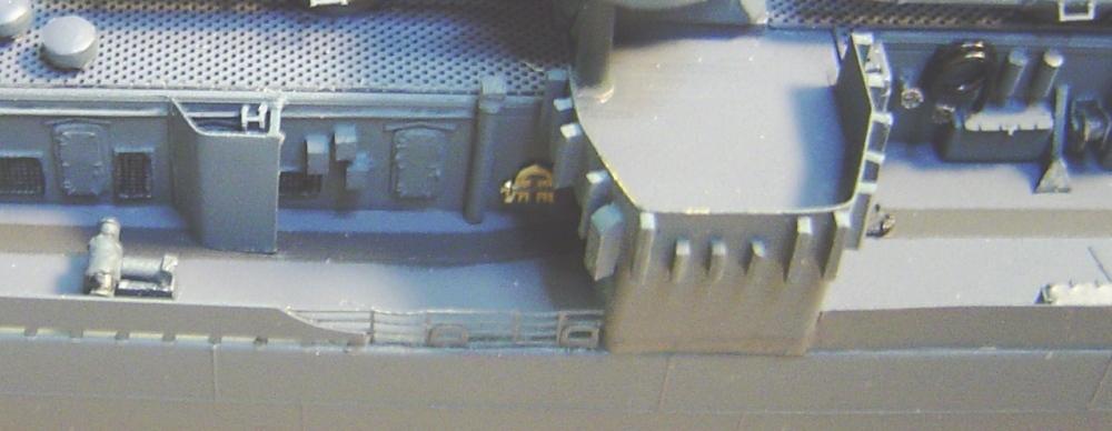
STEP 18 - THE FANTAIL, DEPTH CHARGE RACKS AND AFT 20mm SHIELD |
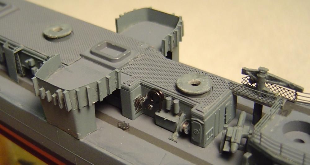
The fantail is looking pretty skimpy so lets work on it. First we need a list of what needs to be done. There is an excellent stern view photo of Nicholas steaming out of San Francisco Bay just after her 1944 overhaul that shows several details.
|
| Here's the completed fantail.
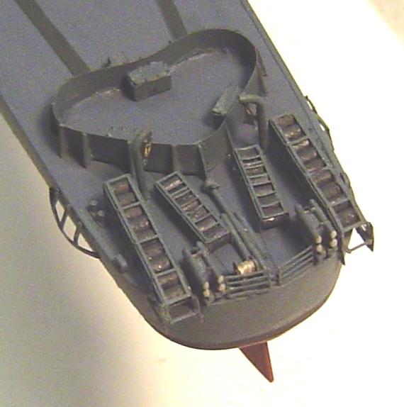
STEP 19 - THE K-GUN RACKS AND THE SIDE 20mm SHIELDS AND RAILS |
The first step is to figure out what K-gun configuration Nicholas had in 1945. There were three designs. The early war design (shown in many early-war Nicholas photos and included in the Fletcher kit) had K-guns and loading davits accompanied by a few extra depth charges on stands or something. The standard mid-war fit had a davit a K-gun and a single row stowage rack. The standard late-war fit had a davit a K-gun and a double row stowage rack. Common sense tells us that she had the mid-war fit. But photos of Nicholas do not support that theory. In fact, evidence to the contrary is almost overwhelming. A photo of her port side as she was leaving San Francisco Bay after her 1944 refit clearly shows a sequence of nine depth charges on racks. That would only be possible with the late-war double stowage racks. Another photo of her starboard side in Sagami Wan in 1945 shows the same nine depth charges. But, most telling is a photo of her amidships modifications during her 1944 refit. Two K-gun installations are rather accidentally included in the far right edge of that photo. Both show double stowage racks. Its proven for me. Despite having a so called mid-war configuration, she had a late-war K-gun fit with double stowage racks. On some ships the exact sequence of K-gun and rack varied. But, the photo during her refit clearly shows that the double racks were forward of the launchers (the standard layout). So here is a list of what needs to be done.
|
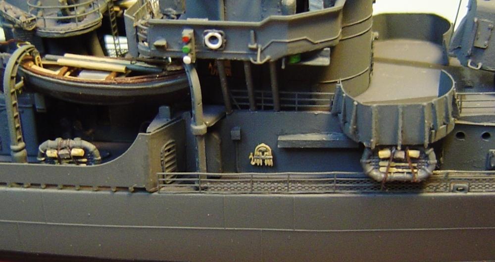
| The assembly of all of the above is actually considerably more complicated than one would suspect and so Im going to suggest a specific assembly sequence that worked for me. First choose a location for the after K-gun rack. In some photos it appears to actually block a chock by sitting directly behind it. This made no sense to me, so I decided to place it immediately forward of the chock. Next, I cut and installed the after railings (GMM PE for Tamiya) between the chock in question and the stern depth charge roller racks. I had to trim just a bit off the aft end in order to get it to fit properly by the roller racks. Everything forward of the chock gets trimmed off. Early war K-guns had rails in front of them but mid and late war versions did not. You can now replace the missing chock on the aft portion of that rail. Then I installed the K-gun racks, launchers and davits with just a short space between each rack (which I filled with a bit of railing). Next, I added the 20mm shields followed by the leftover railing from above, cut to fill the space between the shield and the forward K-gun rack. The last task was to add the railing between the aft end of the spray shield and the forward edge of the 40mm support structure. This is a problem. The GMM PE set provides the correct railing segment (the late war rail segment for the Trumpeter model). But, unfortunately, its curved forward end does not match the aft end of either the Tamiya or Eduard spray shield. The rail segment made for the Tamiya kit does match adequately, but does not include the chocks that existed in this area in the mid/late war fit. I chose to trim and modify the rail segment made for the Tamiya kit and to add two GMM PE chocks to the rail unit on each side. Here's a port view of the completed K-Guns and racks, 20mm shield and ammo boxes and another port view of the winch (portside only) and rails and chocks.
STEP 20 - THE FLOATER NET BASKETS |
These are already going to be hard enough to install and once the mast and rigging are done they could be near impossible. So, lets get them done now. Photos of Nicholas in 1945 show four baskets, two on the aft edge of each stack platform. There were several other popular locations for baskets on Fletchers. But, the 1945 photos are clear enough to tell that there were none at these other spots. The trouble is that the Eduard PE set only provides 3 floater net baskets and the GMM set provides none. The kit also fails to provide any. Thats normal. So, Ill go to a GMM generic floater net basket PE set for the parts. Ill fill each basket with 20 or 25 short bits of .025 rod painted dark gray.
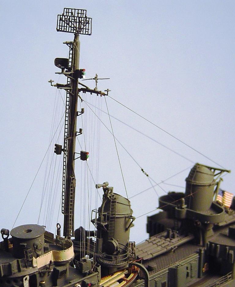
STEP 21 - THE MASTS, STAYS, HALYARDS AND ANTENNAS |
Im going to build the mast with its radars and add the halyards, stays and antennas next. You may have noticed that I have not yet built or added the life rafts. Thats because in 1945 Nicholas had two rafts mounted forward that were outside the rails. And the forward rails (which have not yet been added) always seem to be finger traps that are easily and often broken. Ive learned to add them nearly last. The life rafts will come after those rails. Nicholas mast is not difficult. And there is only one of them. By 1945 she had no mainmast (after mast). I am not going to use the plastic mast from the kit. Thats because plastic masts all too often break and almost always bend once rigging has been added and tightened. Also, exactly everything that is attached to the plastic mast needs to be removed and replaced by PE anyway. So whats the point in all that removing and sanding? So, Ill make a new mast from 1/16 brass rod. The only problem is that it is not tapered. If I had the correct machine tools, I might do that. If I thought it was a large problem, I might see if there was a tapered brass mast available from someone online. But I dont think its a large problem. In fact 1/16 is a little thinner than the base of the plastic mast and a little wider than its top, The rod will be 3 1/8 long with items located on it as follows:
|
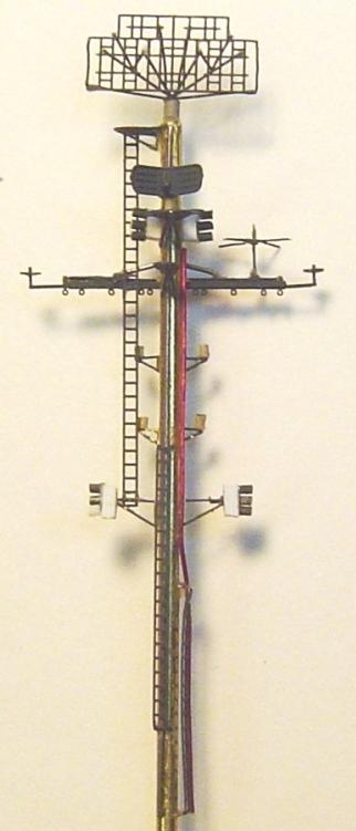
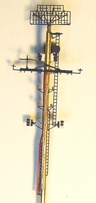
| You may be wondering why this is ¼ longer than the plastic mast. Its because the 1/16 rod is thinner at its base than is the plastic mast and therefore drops farther into the mast mounting hole on the deck. Knowing long ago that I would be using a 1/16 brass rod for the mast, and knowing that it would be a different size at its bottom than the plastic mast, I chose not to include that small mounting grommet in the mast mounting hole. That would have required a perfectly correct bend near the mast base (as exists on the plastic one) and still wouldnt have fit quite properly. Test fit your mast. You will have to search a bit for the deepest fit in the mounting hole just a bit forward (at the base) of the vertical position. The mast did angle slightly aft. If youve found the right spot, a point 1 1/8 up from the mast bottom should slip correctly into the mounting bracket on the back of the bridge assembly. In 1945 Nicholas carried two radars on her mast. She had an SC-2 with IFF mounted on the mast top. She had an SG mounted on a platform (position to be determined later by visual fit due to my intent to use the Eduard slightly oversized but very attractive SG radar PE) between the yardarm and the SC-2. She also had BK antennas on the yardarm ends and a TBS antenna on the port yardarm. In fact, her mast looked identical to the layout described under the title Mast Details in the GMM PE instructions. The first step is to assemble the mast and all possible details. For your convenience, Ill list the work done to the mast roughly in the order in which it was accomplished.
|
| Surprisingly, I can find no evidence at all of either handhold or foot rails on Nicholas yardarm. That seems to be the case for all Fletchers. I pity the poor BK antenna maintenance guy. Fore and aft photos of the mast ready for painting
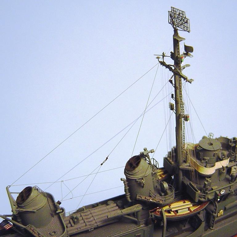
Then, Ill airbrush the entire assembly Navy Blue, and brush paint the lights. One last step is to add the yardarm upper stay. Then add the assembly to the model. Now its time for the always eyesight challenging task of adding the stays, halyards and antennas. For this task I use human hair my own. I am lucky to be blessed with excellent near eyesight, a steady hand and relatively long hair that today comes in a mix of dark brown (stays and antenna wires) and white (halyards). Hair has many advantages. Its small enough to fit through the smallest hole. Its very strong and can take a lot of pressure (the model parts will break off long before the hair breaks). When under tension, it cuts precisely with just the slightest touch of a knife. It sticks to CA glue even better than fingers, in about a millisecond. It lasts for 1000s of years. It can be easily and quickly dyed to any color you wish. The only disadvantage is that it changes length with humidity. You remember that 4th grade science experiment when you made a humidity meter from your hair, dont you? This problem is easily solved by coating the hair with liquid Teflon. Where do you get liquid Teflon, of all things? At the sporting goods store. Its a relatively new and very effective snow ski wax. Just run the hair across the pad and wait a little while for it to dry. First, in order to strengthen the mast and hold it in position, Ill add the stays. There are 2 on each side running from those two turnbuckles that I added to the bridge wings and one stay running aft, splitting and attaching to the inboard loops I added to the forward edge of the aft stack platform. I used a GMM PE turnbuckle at the connection point. Then add the halyards. I had some difficulty here with access to the flag bag pinrails and had to remove (and later re-install) the MK27 torpedo directors. Last, add the antenna wires with a lead-in connection to the antenna insulator that I added port of the aft stack back in step 16. And that should do it. Although many late-war Fletchers had a few whip antennas here and there, I see none in any of the photos of Nicholas. One last noteworthy word is that I am not certain that the rigging and antenna arrangements that I used are 100% accurate for 1945 Nicholas. The photos are poor and rigging just does not show up well. There are a few close-up photos of her during her 1944 overhaul and, based on those, I am quite certain that the mast stay design that I used is correct. The elusive item is the antenna wire arrangement which varied significantly between ships. I used a common design that at least is not obviously different than what Nicholas appears to have carried in 1945. Fore and aft views of completed mast and rigging
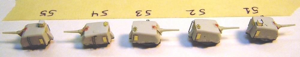
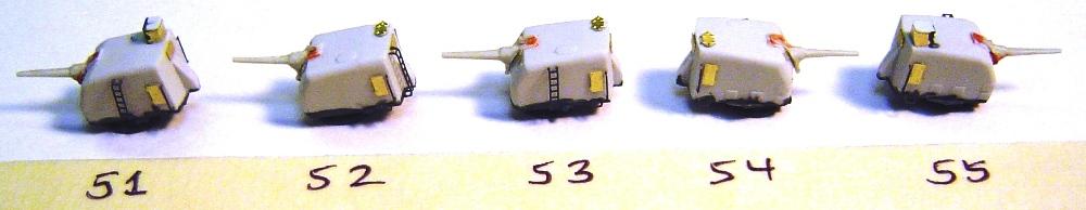
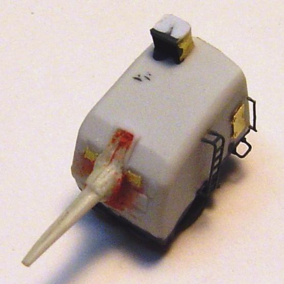
STEP 22 - THE 5"/38 GUNS |
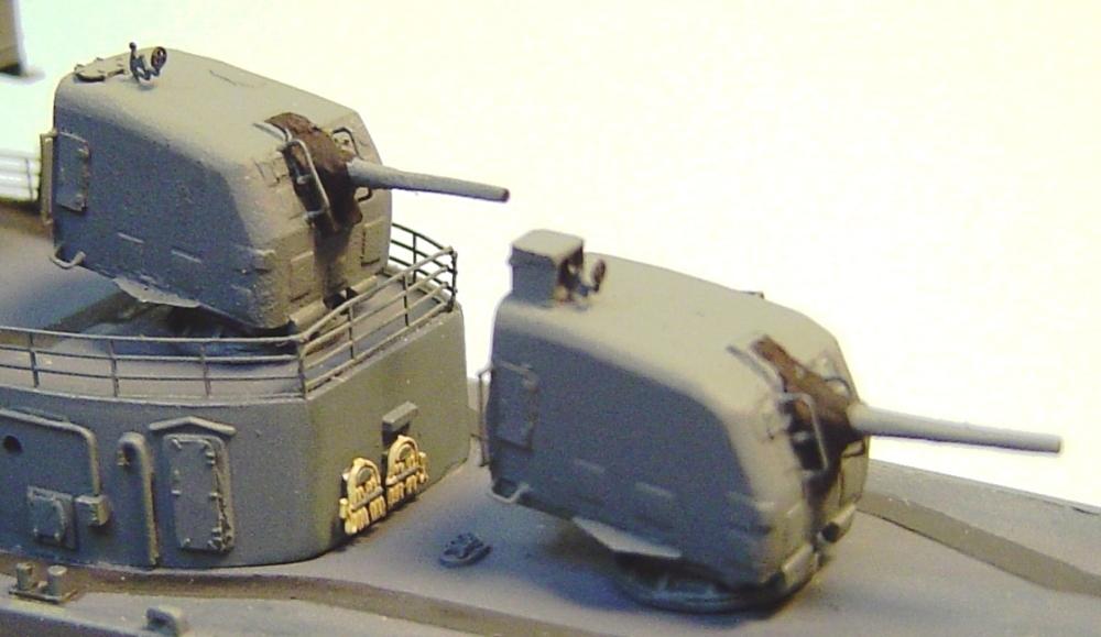
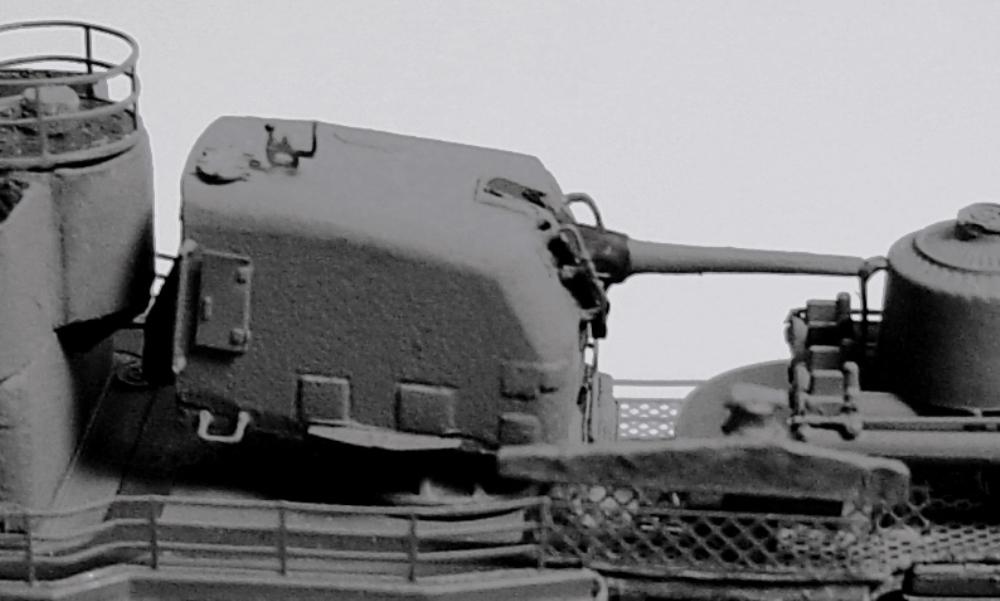
Ill be using the excellent quality Corsair Armada resin 5/38 guns. There are many possible options in assembly, so its worth getting organized and listing the features and appearance of each of the five guns numbered 51 (foremost) through 55 (aftmost). Gun 51 - double knuckle, sloping base, portside ladder, cover over gunners hatch. There is only a very little minimal molding cleanup required on the gun bodies (these could be the cleanest resin molds Ive ever seen). No putty was required. Add the mounting base being careful to properly orient the sloping bases on guns 51 and 52. Add the PE supplied with the Corsair Armada kit, but I chose to delay the addition of parts 7 until after the barrels were added. Good thing I did. The barrels dont really fit all that well. I was tricked by the parts quality into forgetting that these were resin parts. I used the level barrels with blast bags (bloomers). The single knuckle barrels fit fairy well, with only minimal filing, on guns 52 to 54 but the double knuckle level barrels with blast bags were a very difficult fit with a lot of filing and some putty required. This is my only complaint about these otherwise excellent guns. Well there is one more small and expected complaint. Some of the barrels, being resin, were bent and required some heat and effort to straighten. Normally, because of this, I never use resin barrels. Perhaps I should have tried to adapt the kits plastic barrels or just gone ahead and ordered brass ones. I added pre-painted ladders to the correct locations, scratch built (brass and styrene) protective covers over the gun captains hatch on guns 51 and 55 (they prevented his head from being blown off if the gun behind him fired while he was looking out of his hatch), some GMM generic hatches for the gun captains hatch on guns 52 to 54 and a bit of narrow stanchion railing served as handrails on the gun entry hatches (aft on each side). I pre-painted in Navy Blue the interior of the gun captains covers and the bases and undersides of each gun. PE parts 7 will be added later. If it was added now it would be impossible (for me at least) to paint the bloomers (blast bags) black as was the case on Nicholas (on some ships they were cream or buff canvas) without also painting parts 7 black (which should be Navy Blue). The 5" guns starboard and port views and detail views of gun 51, ready to paint
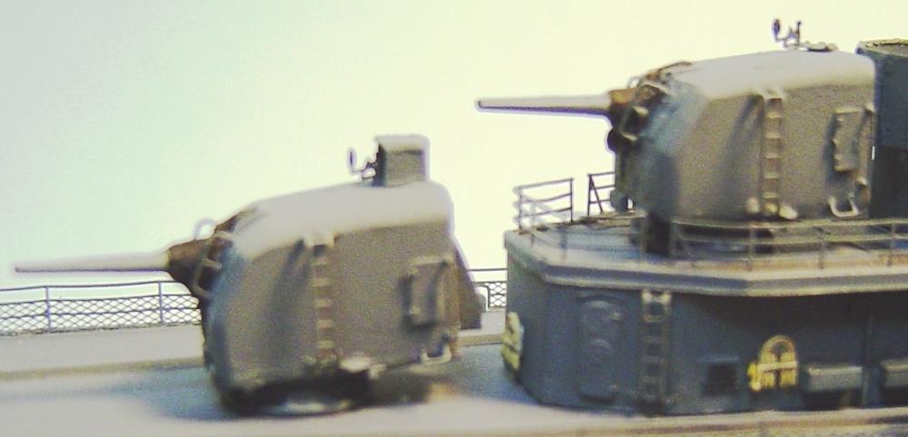
Close-up photos of Nicholas at the end of her 1944 overhaul show no evidence that the tops of the guns were painted Deck Blue. The color is continuous from side to top. So the next step is to airbrush all surfaces of the guns Navy Blue. Then paint the bloomers (blast bags) Flat Black. Then add parts 7 on each side of the barrels. Finally Ill add the gun captains sights. Based on photos, there is no doubt at all that these existed on the 5/38 guns on Nicholas. In fact, they were standard on all US Navy 5 guns, in the event that the gun had to be manually operated. The PE for these sights should be included in the Corsair Armada PE. Usually they are included in GMM PE, but unfortunately, not in this case. Luckily, the GMM PE sets for any battleship includes these sights with several extras. Having recently modeled several battleships I happen to have several extras and will use them here. I can find no evidence that these are available in any PE set other than GMM PE for various US battleships. 5"/38 guns painted and installed
STEP 23 - THE MK37 DIRECTOR AND MK12 RADAR |
Assemble the kit's MK37 per the instructions. Ill also do some filing, clean-up, add some detail and replace the molded side ladders. In 1945 Nicholas had a MK12 but no MK22. Ive built the GMM MK12 more times than I care to remember, so this time Ill build the Eduard version. Actually it goes together well and produces a very respectable MK12. But, Nicholas had some support framework forward of the MK12 which is not represented in the Eduard PE. So, Ill use a couple of short bits of wire for those braces. Like the 5 guns, a close up photo of Nicholas in 1944 shows no evidence of a different color on the tops of the MK37. So, the next step is to paint the entire assembly Navy Blue. Then paint the bloomers around the side sights Flat Black and I used just a tiny touch of Metallic Gray on the ends of the sights. Allin-all it turned out pretty good for something built from a plastic kit part. The Eduard MK12 PE was an interesting change from the GMM and, I think, produced a slightly better result. Finished MK38 and radar
STEP 24 - THE SCREWS, DECALS AND FORECASTLE |
Add the screws being careful about which one (they have different part numbers) goes on which side. Now, lets add the hull decals. I can find no photo of Nicholas during the war in which she has her name painted on the stern. This was fairly normal during the war as an anti-identification process. There is a photo of Nicholas stern while tied up at Yokohama that clearly shows no name on the stern. However, she did carry hull numbers forward and aft. Ill use the 24 white numbers from a GMM WWII aircraft decal set. You could use any other decal set or make your own. Next, lets go ahead and finish the forecastle. There are several items to be added here.
|
STEP 25 - THE LIFE RAFTS |
Now that the bow rails are done, the life rafts can be added. As previously mentioned, in 1945 Nicholas had six life rafts. There was one on each side forward beneath the 40mm tubs outboard of the rails, one on each side inboard of the spray shield beneath the boats and one on each side aft on top of the standard aft life raft racks. There is no photographic evidence that the forward raft rack was installed. But, there actually seems to have been a seventh raft. Photos show a smaller raft on top of the starboard aft rack-mounted raft. Photos of her port side do not show a similar small raft there. Curious. What type of raft could this be? Nicholas rafts were clearly of the oval type (not rectangular ones) and as far as I know those only came in 40 man and 25 man sizes. And, its pretty clear that the rafts on Nicholas were 25 man versions. Obviously a smaller raft version existed (and thats really not all that surprising anyway). Plans of Nicholas (Fletchers in general) do not agree with the photos. Plans are very useful for modelers, but also remember they are only the plans. The bottom line on what a specific ship looked like at a specific time is in the photos not the plans. And, unfortunately it is clear from photos, despite what the plans show, that Nicholas had an additional very small life raft stacked on her starboard side and had a somewhat abnormal raft distribution. The plastic rafts in the kit are just a bit oversized and are very lacking in detail. The Eduard PE provides PE inserts to cause the bottoms of the kits rafts to look a bit more realistic. But they are designed to fit inside the edges of the raft rather than to be attached to the bottom after the plastic bottom is cut out (as is normally the case with most PE raft enhancements). Unfortunately, the GMM set provides nothing to help with the rafts. The best 25 man oval rafts that I have come across are the ones included with the Yankee Model Works kits. They consist of a high quality and high detail metal oval and some PE lattice that fits over the bottom. Unfortunately, Yankee does not sell them separately. I only have one spare left and dont feel like spending several hundred dollars to get 5 more. The next best are normal plastic kit ones in which you cut out the bottom and glue on a new PE lattice bottom; which is commonly included in the GMM PE sets for most kits. But, for some reason, they didnt include those this time and the Eduard ones are too small. I do have some extra PE bottoms and could take that route but the problem still remains that the rafts in the kit are too large, too lacking in detail, too thick and it would be a lot of work to get them filed to the right size. So, Ill go to the third best approach, which is to use the metal 25 man oval rafts that Yankee Model Works does sell individually. Life rafts, much like whaleboats, are an opportunity for you to artistically express yourself. Yes, in WWII they were dark blues and grays rather than modern orange, red and yellows because the occupants would much prefer to be missed by friendly forces than spotted by Japanese forces. Nevertheless, you can make a WWII life raft look pretty good. Strangely, most plastic kits do a poor job with life rafts. Often there is a serious shortage of them. And, rafts being located in very outboard and very visible locations provide an opportunity for much more colorful detail. In addition to using the better quality Yankee oval rafts, Ill use some left over oars from a LArsenal raft set and Ill make tan water barrels and gray equipment boxes from some styrene. Ill also add thread for tie-downs in the configurations indicated by the photos. Ill make the mysterious small raft by cutting a kit provided plastic raft into quarters. Then Ill trim about 10% off the height and width of each quarter and glue the four parts back together. Presto I now have a raft thats about 20-25% smaller than what I started with. Starboard view of the forward and aft (stacked) rafts
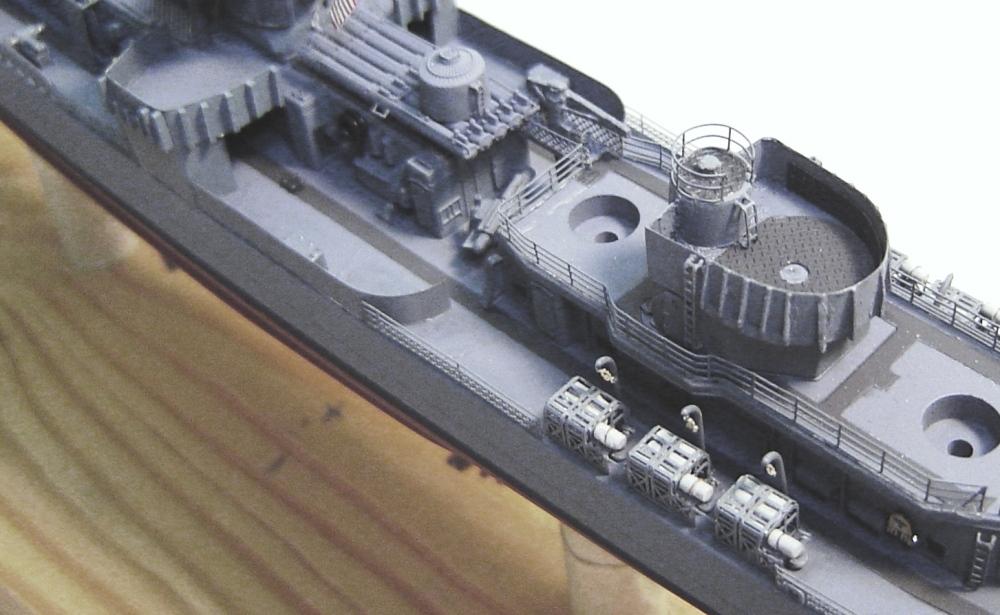
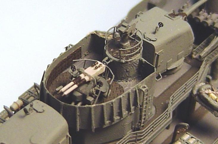
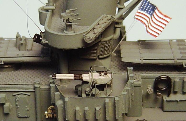
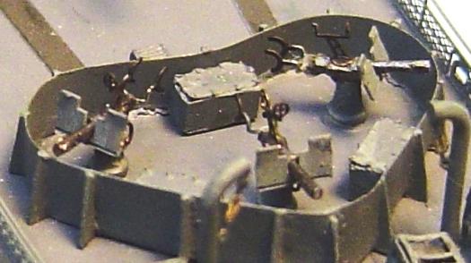
STEP 26 - THE 40mm GUNS AND MK51 DIRECTORS |
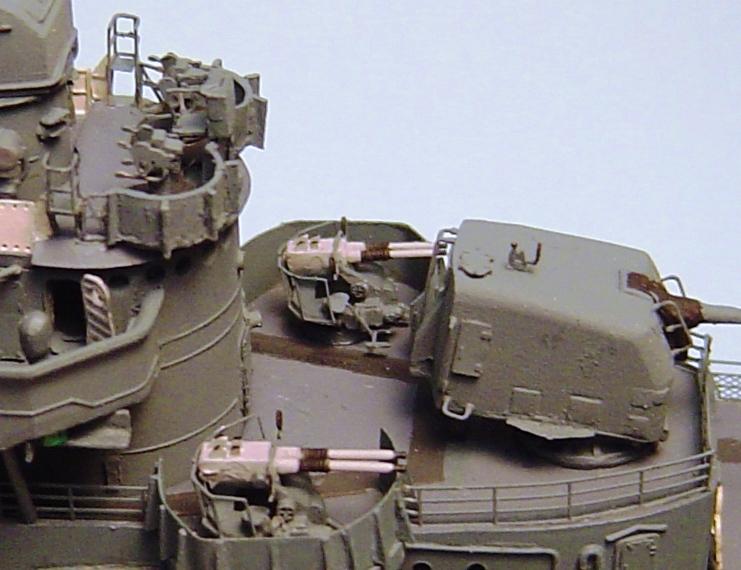
Ill be using the excellent quality LArsenal twin bofurs guns and directors. The kit does not include enough for a mid or late-war outfit. There is always a question of color on the 40mm guns and MK51 directors. Instructions nearly always suggest that they be painted a light gray. And, that makes for a nice contrast against the normally dark blue decks and allows their detail to be more visible. My inclination is to do that here in order to show off the excellent detail of the LArsenal guns and directors. However, its pretty solidly clear from photos of Nicholas that in 1945 both devices were painted Navy Blue just like all other parts of the ship. So, in the interest of accuracy, Ill paint them Navy Blue. But, so that at least a bit of the detail can be preserved, Ill paint the barrels Haze Gray with Flat Black recoil springs and other details. The sights will be Flat Black. Following the LArsenal instructions, Ill make 5 identical guns and directors. No plastic kit parts will be used. When adding the guns and directors to the model, be sure to properly coordinate the headings of each gun and its associated director. Gun and directors 41 & 42 - Gun and director 45 - Gun and director 44 (43 identical)
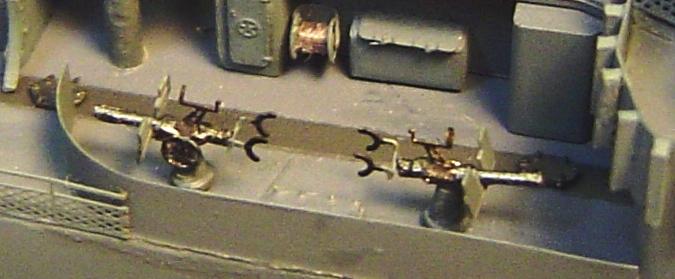
STEP 27 - THE 20mm GUNS |
Im going to build these around the plastic gun bodies that came in the kit. Some modelers swear by PE 20mm guns and insist that nothing else is accurate. But, honestly I prefer the 3 dimensionality of plastic gun bodies. Someday I intend to try plastic 3d gun bodies with PE barrels. Although I have some extra PE guns, I think Ill save them for some other model that needs them more. Generally, I would say that usually the Tamiya guns are the best plastic guns Ive seen. Nevertheless, considerable enhancement is required to make good looking 20mm guns. The first enhancement is the splinter shields. There were actually at least three different shields used during the war. The earlier shield was perfectly rectangular on each side of the barrel (as are the GMM PE shields). The mid and late-war shield was notched or angular at the top. But this did vary considerably from ship to ship. Photos are the only accurate information source. Photos of Nicholas after her 1944 refit clearly show her equipped with the later style notched shields. The Eduard PE shields properly represent this design (and have a bit more detail anyway). But the Eduard PE set only includes 6 of them and 7 are needed. Darn it! So, Ill change to a new sharp Xacto blade and see if I can cut notches in the inside tops of one GMM shield. That worked well enough on the second try. So Ill use the Eduard shields painted Navy Blue and add the one altered GMM shield (which has no detail support braces on its back) on the forward gun on the port side where its back is essentially invisible. Otherwise, Ill be using the other GMM PE enhancements (elevation wheel, shoulder rests and gun sight. Ill paint the gun support bases Navy Blue. The gun bodies will be Tamiya Gun Metal. The PE shoulder rests will be Navy Blue and Flat Black. The elevation wheels will be Metallic Gray and the gun sights will be Flat Black. Follow the GMM assembly instructions and youll end up with some very nice 20mm guns. Photos of the starboard amidships and stern 20mm guns
STEP 28 - THE FINISHING TOUCHES |
This step should probably be called forgotten items. Despite lists and instructions there are always a few things that get missed or are noticed too late and have to be added later. The ships bell. More life rings Something unknown Stokes litters Torpedo crane hooks Boat ropes
STEP 29 - SAILORS MANNING THE RAILS |
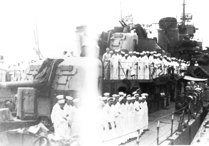
On 2 September, at the Yokohama Customs House Pier, Nicholas embarked 87 Allied representatives for transport to the surrender ceremony on Missouri. And the crew was in whites manning the rails like no rails had ever before been manned. But, surprisingly, they were not in dress whites. The officers were clearly in khakis and the sailors in either undress whites or shirt whites (did they have that uniform in WW2 I think not). Nevertheless, there were no neckerchiefs. Okay, theyre kind of hard to paint well anyway. Ill use about 150 normal GMM PE flatfolk, painted up nicely and set in lines.
CONCLUSION |
This project took 176 hours. Thats about 76 hours more than I had estimated. But, although I tried to eliminate recording of research time, I suspect that at least 1/3 of that time was research in just thumbing through photographs looking for some specific item that I knew I had seen somewhere but couldnt recall. Also, it was my first build of the Tamiya Fletcher kit, so getting familiar with that kit and deciding which PE to use and which items to scratch build accounted for another 20 or 30 hours. I suspect that if I ever did it or something similar again, it probably could be done in 100 hours or a bit less. The Tamiya kit The PE sets The Eduard set is also excellent quality and detail. It is not designed as a replacement for the GMM set, but rather as an enhancement. By itself it would do a poor job of detailing a Fletcher. It also is designed very specifically for an early war Fletcher class ship and provides no mid or late war details. I would certainly use this set on any future early-war Fletcher build. But I question its value for a mid or late war build. If cost is no issue, in that application it offers a few nice additional details. But, if cost is an issue, then it really doesnt add all that much to a mid or late-war build that cant be created with some brass sheet and styrene. The accessories The approach | ||||||||||||||||||||||||||||||||||||||||||||||||||||||||||||||||||||||||||||||||||||||||||||||||||||||||||||||