| Back to Menu |
|
|
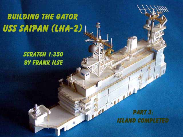
| The cramped island structure aboard aircraft carriers always fascinates me. All these rooms to sail and lead the ship and task force combined with the sensors and antennas for navigation, survey and communication. I did already describe the basic island-structure for this scratch-built Gator in part one. Now it comes to detailing. Lets start with the main mast, sitting on the after part of the island. Basically this mast is a rectangular structure with three rectangular electronic platforms and a sturdy polemast. I startet setting the four mast-pylons first. Three of them are made from 1,2 mm rod and one, looking from astern in front on portside, is angled. Its where the cables run up the mast to the different electronic installations. Having glued and adjusted the pylons, I cut the platforms from 0,75 mm styrene. The girders and stringers for every platform are cut from 0,5 mm strip. I always cut larger pieces for the girders and glue them to the platform. Cutting them to shape afterwards brings out the clear and sharp edges you need.
|
click images
to enlarge |
 |
|
|
|
| Using a small file I made notches in the platforms where the pylons fit in. Then I glued the platforms between the pylons and made a border strip for every platform from 0,25 mm sheet. The cross-ties and struts followed, made from 0,75 mm rod. Every strut and cross-tie
was cut to size seperately. Quite a tedious job with some of the parts but very rewarding.
Setting the pole-mast was comparatively easy. I used some sprue sanded to shape and made an angle from 2x3 mm strip as a base. This was glued to the other construction. And so we rise to the next floor.
|
 |
|
|
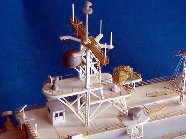
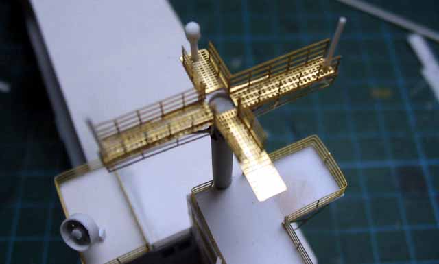
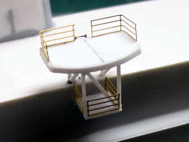
| Research at the starting point of this project showed, that a 1:350 Enterprise-photoetch-fret would be an excellent set to get railing, hose reels, flightdeck netting, electronic equipment and mast platforms for my Gator. I ordered one from WEM. Some cutting and minor changes made for an excellent platform on top of the pole, very nice with perforated walkways. The platform got struts made from 0,2 mm steel wire and railing. I took the SPS-10 navigation radar from the fret as well as the SPS-48 3D antenna. This was cut to size and modified to get the SPS-52B that was installed on the Tarawas around 1990.
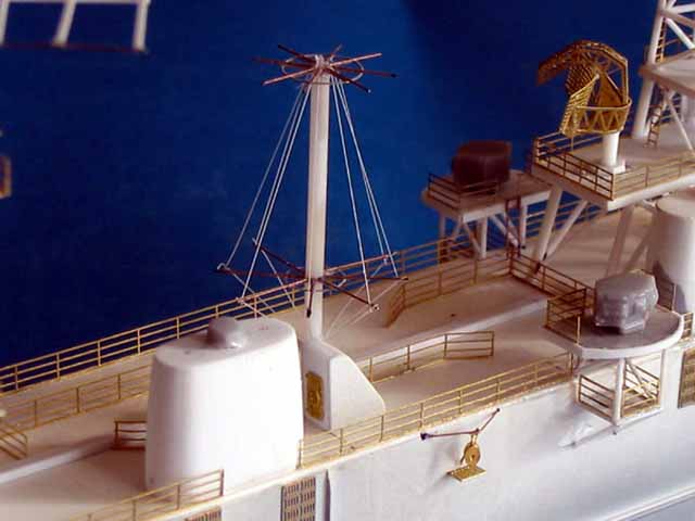
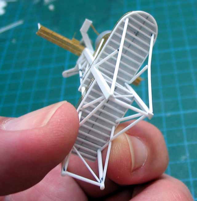
But there was still one antenna left: the very prominent eye catcher on top of the mast, the communications-antenna looking like a flyswatter as one of you modelling friends called it on the forum of this site. The shaft is made from 0,5 mm strip and the braces are cut from 0,5x0,25 mm strip. I bent very thin steel wire - in fact an old guitar string - to shape and glued it to the end of the braces. It was far easier than I had anticipated
|
 |
|
|
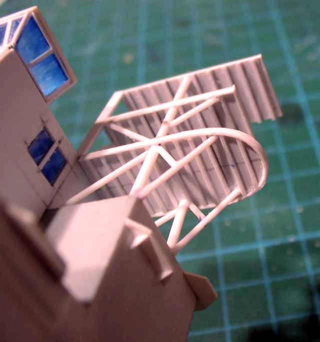
| Next step to take was the foremast. Construction is similar to the mainmast, but this time I decided to build it up separately and glue it to the island afterwards. Basic structure is two angled profiles connected by two platforms. This was done first. The platforms got girders and braces and were glued to the pylons. Followed by struts and cross-ties up to the second platform made from 0,75mm and 0,5mm rod. In a second step I did the mast-construction above the second platform. First step is always to glue and adjust the four pylons followed by cross-ties. Let everything dry and cure before glueing the diagonal struts to avoid tortion.
|
 |
|
|
| Construction goes in basically four steps: sidewalks, middle complex, floor and ceiling-construction.
If you like, you can add tanks and personnel as part five. Here we go-
|
 |
|
|
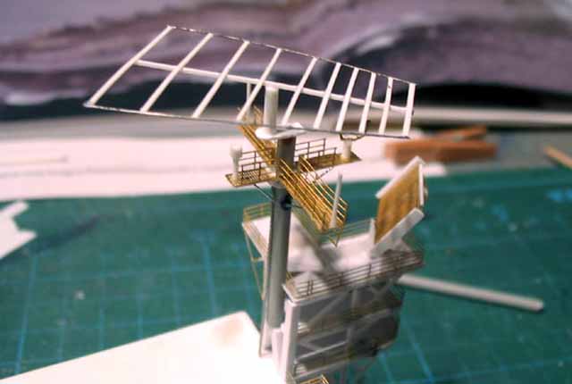
| The SPS-40 antenna on the lower platform was taken from the spares box. The platform on top of the mast is made once more from different parts of the Enterprise- PE-fret. As well as railing and weather vane. The director and radome were taken from an old Dragon Spru-Can kit as the Spruance class and the Tarawas used the same type of directors at that time.
|
 |
|
|
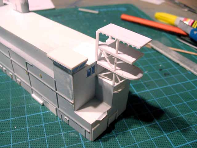
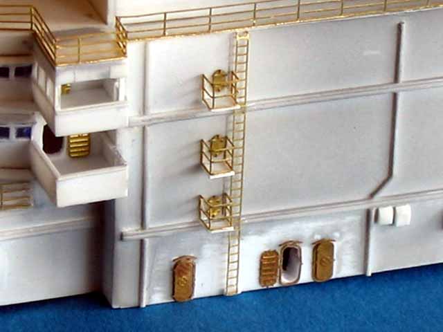
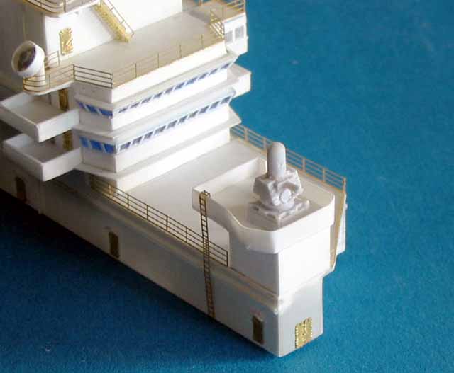
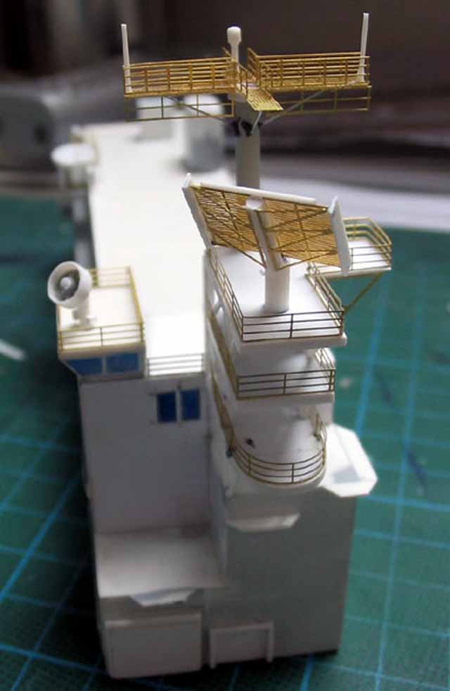
| The ECM-platforms came up next. This was a nerve wrecking task. First step was to cut the lower part of the platform to size, erect the tiny pylons and the railing between them. Having this done the platform was glued to the islands sidewalls port and starboard. Then I measured and cut the rear pylons and glued them to the top of the island. This work required a lot of test fitting. The struts made everything steady. Pylons and struts are cut from 0,5mm rod, the platform is from 0,75mm sheet with a border strip from 0,25mm sheet. Two bits of photoetched railing and a ladder complete the step. The ECM- system is taken from the spares box. Each platform is made from 22 parts and it took quite a time, not to talk of swearing and cursing.
|
 |
|
|
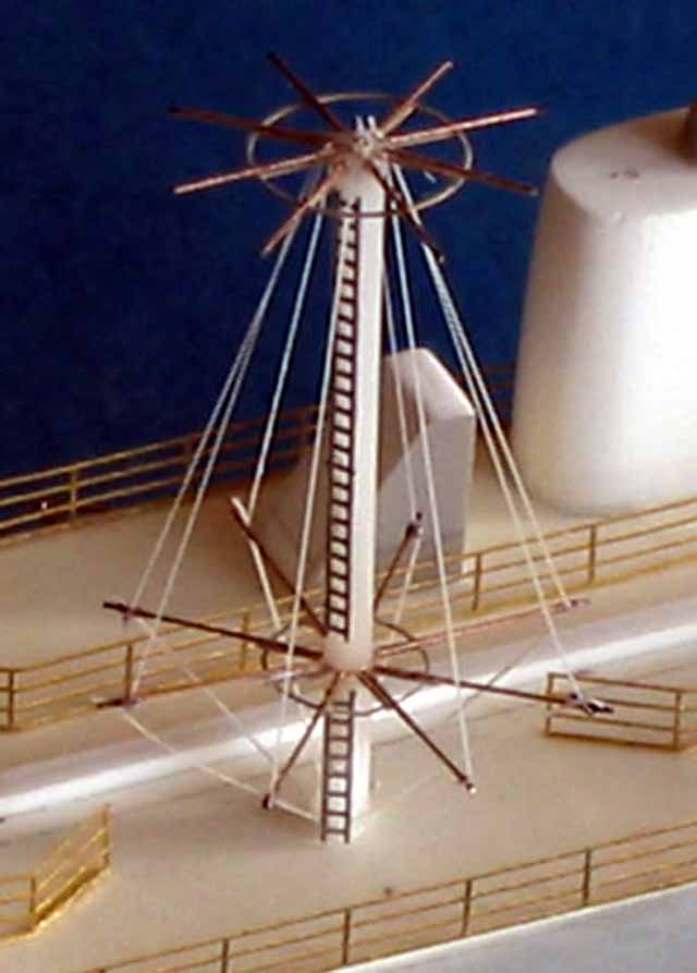
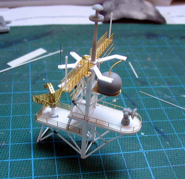
| And there was still this communications antenna between the masts. As a leftover from my Long Beach kit I had two photoetches antenna stars. These stars were extended using 0,2mm brass wire. I superglued a piece of 0,3mm steel wire through the centres and connected the stars using 1,5mm styrene tube, followed by the photoetched ladders. The wiring is made from stretched sprue.
|
 |
|
|
| Final work to do was superglueing railing to the island, add some platforms here and there and finally install a Phalanx gun. This one is a resin piece and comes from WEM.
It took me four months to detail the island. Simply because this is a task you only can do with considerable breaks. At least for me.
. |
 |
|
|
|
|