| Back to Menu |
|
|
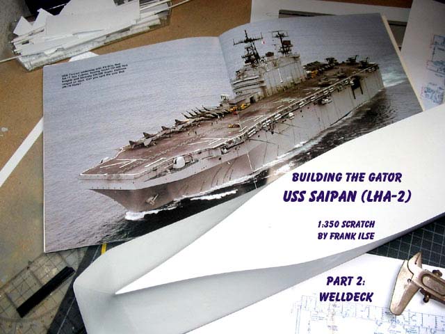
| Having started the buildup feature of my 1/350 scale gator
USS Saipan with the basic construction of hull and island, I now will proceed
with the first component to be completed: the well deck. I detailed it
as much as possible because it will be visible later on, although the hangar
bay and the flight deck are above. But I found a way to make them free
to move later on. But first, some data. |
click images
to enlarge |
 |
|
|
|
| The ships of the Tarawa class are swimming Heliports with an additional
feature. Like a submarine they can go down controlled. To a certain extent
that is. Huge pumps and flood valves fill ballast tanks that enable the
ship to lower its stern about eight to nine feet. Through the opened gate
at the ship's stern water flows into the well deck. |
 |
|
|
| This technique enables the Marines to board the landing craft with
dry feet as long as the well deck is dry. After boarding, the ship's crew
floods the deck and the landing craft, whether LCU (Landing Craft Utility)
or LCAC (Landing Craft Air Cushion) leaves the well deck via stern gate.
The United States developed this technique during WWII. LSD (Landing ships
dock) were introduced to the amphibious operations from 1944 on to the
end of the war, featuring a similar construction. A modern amphibious force
incorporates an LHA, Tarawa class, or an LHD Wasp class as core and flagship.
Two LSDs, frigates, destroyers and an Aegis-cruiser are normally added.
USS Saipan is currently the core of Phibron 2. She sails together with
USS Trenton LPD 14, USS Oak Hill LSD 51, USS Hue City CG 66, USS The Sullivans
DDG 68 and USS Underwood FFG 36. Homeported in Norfolk, Virginia, the ships
motto is Ready to Strike. |
 |
|
|
| Modelling a well deck can be finger-twisting and has a lot to do with
adjusting, aligning and test fitting. For two main reasons: the huge deck
in 1/350 scale shrinks to mere 30 centimetres lengh, 9.5 centimetres wide
and only 2.7 centimetres high between decks. And I wanted it to be visible.... |
 |
|
|
| Construction goes in basically four steps: sidewalks, middle complex,
floor and ceiling-construction. If you like, you can add tanks and personnel
as part five. Here we go- |
 |
|
|
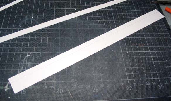
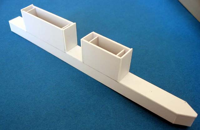
| First of all you draw some reference lines on the inside of the hull,
port and starboard side. They mark the well decks height. This was followed
by cutting the inner sidewalls from styrene-sheet. I used 1 mm basically
throughout the well decks construction. Behind the inner sidewalls are
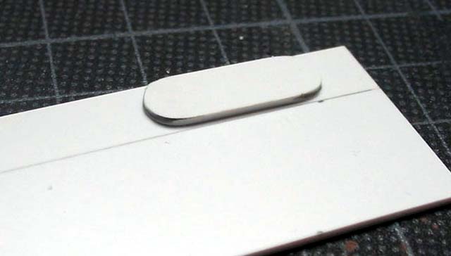
walkways for the crew handling the landing craft. From stern to bow there
are different stations marked to make orientation for the crews of landing
craft and amphib-tanks easier. The walkways connect to the well deck via
large oval openings that hat to be cut out next. I made a template to mark
the positions and carefully started cutting out the ovals on port side.
What a tedious job. So I tried another method on starboard side using an
eight millimetre drill for the rounded sides of my ovals. It worked well
in a split of time. Scratchbuilding really is a dynamic process. |
 |
|
|
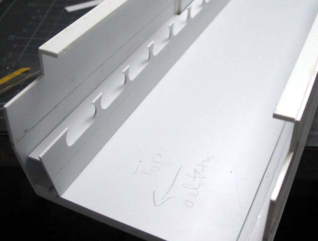
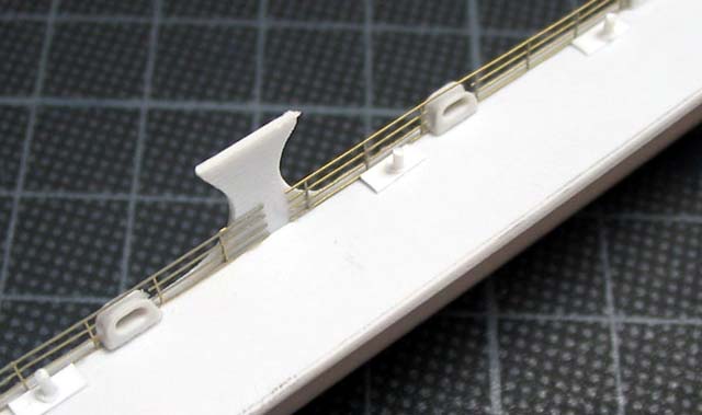
| Right under the oval openings I glued another strip of styrene sheet
in a right angle to the sidewall, my walkway. The openings were detailed
with railing from a generic GMM 1/350 photoetch fret, chocks (fairleads
- for the British), and bollards. Two additional strips were cut as the
walkways backwalls, detailed with fire hoses and doors from a GMM fret
and 0.25 mm styrene rod as piping. Everything was airbrushed in Model Master
Light Gull Grey, even lighted with white, as the well deck areas are in
a very light grey, even white color. The fire hoses were painted red. |
 |
|
|
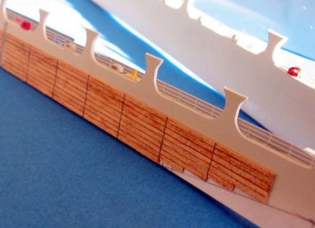
| My Saipan is a real multimedia kit. I use plastic, metal, resin and
wood. The well decks inner walls are planked with wood to avoid damage
from bumping LCU and tanks. This planking is about 0.5 millimetres thick
in 1/350 scale. I used mahogany strips I had left from an historic ship
project and glued them to the sides with superglue. I marked the plank
structure with a hard pencil and painted some planks in white, orange,
red or yellow according to photos of well decks I found on the US Navys
official website. |
 |
|
|
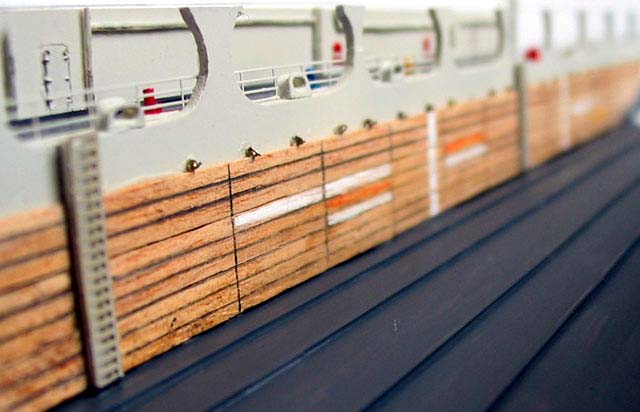
| And now I started to go nuts. Right above the wood planks is a line
of mooring-eyebolts. Leave them off!! shouted a voice inside of me. Go
ahead do it!! whispered another. Well, there was this GMM-fret, I had
used for my Trumpeter Liberty ship and there were lots of eyebolts left
on it. Hmmm.... I started on one sidewall, in the evening, after a glass
of wine or two it worked! Three days later I had two sidewalls with wood
covering and eyebolts. |
 |
|
|
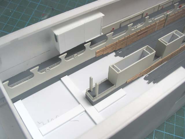
| Step two is the well decks middle construction. The Tarawa successor,
the Wasp class, no longer has this partition, because without they can
take more LCAC aboard. The partitions plan view was easily taken from
my plans, but the side view is a guess I got from several pictures from
the USN homepage and from books, lacking correct plans of it. The partition
is a simple built, constructed from various pieces of 1mm styrene sheet.
After the basic construction everything was filled and sanded to shape
and doors and hose reels from a GMM fret were added. Airbrushing in light
gull grey lighted with white followed. The middle partition got its wooden
planking too and there were even enough eyebolts left for further detailing.
I set everything aside and headed on to step three: |
 |
|
|
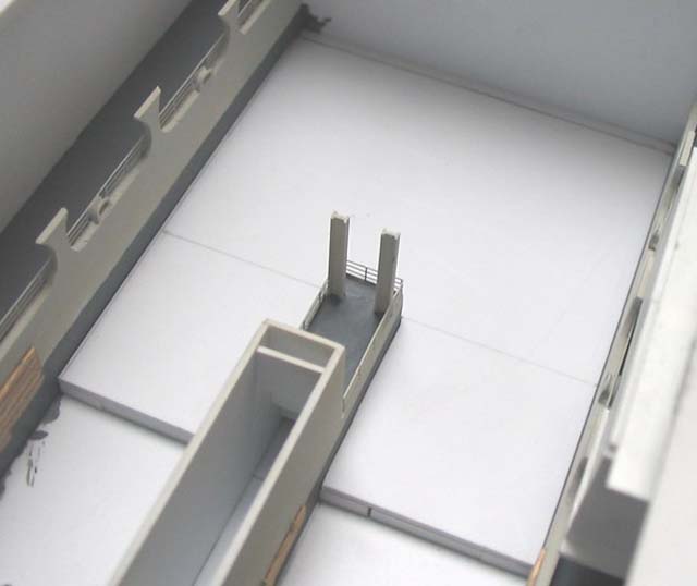
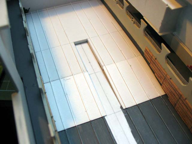
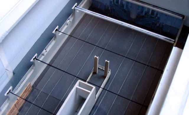
| The floor construction. The well deck floor extends for two thirds
of the deck on an even level and following the way to the ships bow rises
to a higher one. This rise is done by a ramp. The floor has the even structure
typical of a steel deck and shows rails to tie the Marine-vehicles. The
ramp has a rippled structure. |
 |
|
|
| First I cut a floor plate, 1mm styrene, to shape and glued it into
place. With a sharp pencil I marked the position of the tiedown rails and
the partition. I glued down the rails, 0.25x0.5 mm styrene strips, just
up to the ramp and painted the floor in gunship grey (Modelmaster). After
the paint was dry I glued the sidewalls into place. |
 |
|
|
| The rised part of the well decks floor got a substructure of 7x3 mm
strips. The strips were set in a way that the middle construction was fitting
tight in between the strips. I cut a piece of styrene sheet to shape and
sealed that part of the floor. I added the ramps and lacking tiedown rails
and painted everything in gunship grey. |
 |
|
|
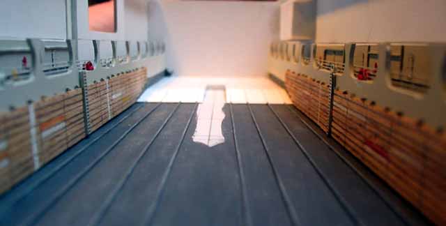
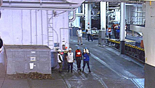
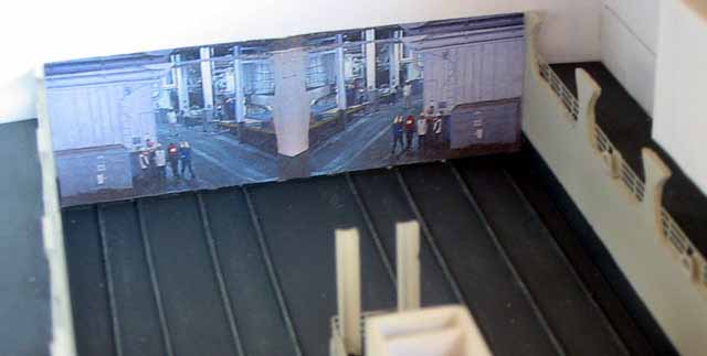
| If you want to take a look at the well deck later, one way will be
through the open stern gate. Doing so, you would squarely look at a bare
white or grey wall, because I will not go into further detailing the ships
interior on that level. This annoyed me - but I found a way out. I looked
for a picture that shows this part of the well deck looking forward and
found one, just one, to be frank, on the US Navys website of course. I
cropped a part of that picture using photoshop and with the help of my
graphics program I mirrored and cut it to fit my well deck wall. Voila
a wallpaper. I glued it into place and now the view goes into distant
compartments. Finally the middle construction was glued into place and
I was ready for the ceiling. |
 |
|
|
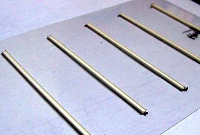
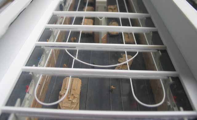
| There is a little catch waiting for you. The well docks side walls
are connected with steel I-beams that carry the rails for the cranes that
run under the ceiling. I had to find a way to mount the rails to the beams
that afterwards had to be fixed between the siedewalls. As a solution I
took a piece of transparent styrene and cut it to ceiling shape. This was
laid onto the sidewalls. Then I marked the beam positions with an overhead
marker from ABOVE. I cut the beams to size and glued them to my ceiling
from BELOW. Checked the correct fit by laying the ceiling onto the sidewalls
frequently. When everything fitted into place I took the ceiling and glued
the crane rails to the beams from BELOW, using 0.5x0.5 profiles. |
 |
|
|
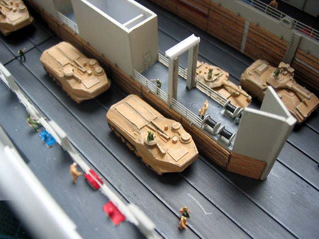
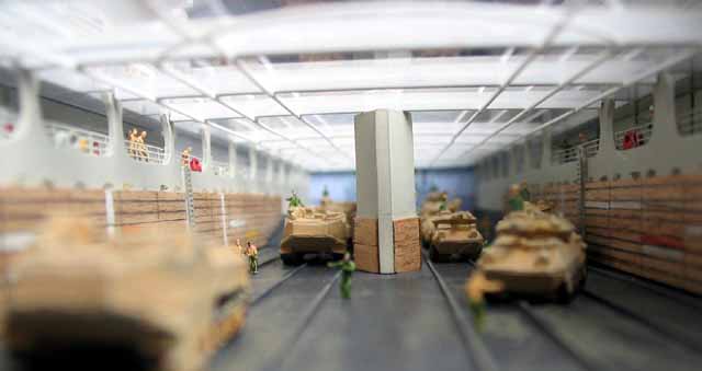
| Now it was time to close the well deck, but I wanted to bring it to
life before. I had already purchased some vehicles from Skytrex, a British
company that provides our wargaming friends: AAVP7 amphib tanks, Bradleys
and LAVs. I airbrushed them in a sand tone, gave them an umbra wash and
highlighted the details drybrushing in a very light sand. I added about
25 figures from LArsenal and Preiser, painted as sailors and Marines.
The personnel and vehicles were scattered throughout the well deck as if
Marines were preparing for debarking. |
 |
|
|
| As a final step I installed the ceiling by glueing styrene strips from
ABOVE and fixing the transparent ceiling that way and in the same way getting
a substructure for the hangar bay that is to follow as one of the next
steps in this built. |
 |
|
|
|
|