| Back to Menu |
|
|
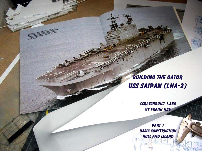
| I always wanted to build an LHA in a larger scale. Most of us know that there is a model kit
in 1/700, offered by Dragon and Revell. But I am into 1:350 and in that scale there is none. So scratchbuilding
is the way to do it. USS Saipan was my choice, basically because there is a great photo feature over on Steelnavy,
done by Cdr. Charles Landrum, when he served aboard LHA-2. I decided to choose the period around 1990, because
I wanted the prominent antenna on top of main mast, that is lacking now as well as the crane abaft the island.
Moreover I am a friend of the three tone green/grey/black camo the helos and Harriers sported at that time.
|
click images
to enlarge |
 |
|
|
|
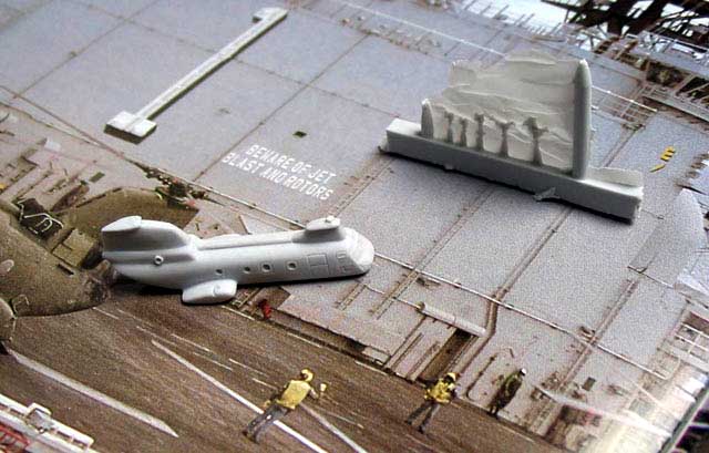
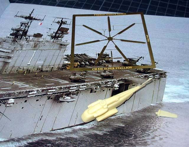
| First research proved promising.
Corsair Armada
and
White Ensign
offer the required transport helicopters in 1/350
actually I got the idea to build a Tarawa from Corsairs first announcement for their Sea Knights.
About nine months ago Commander offered Cobras, Hueys and Harriers as well as decals, so there is no problem
to build up an airwing.
Floating Drydock
offers plans that are especially helpful when it comes to detailing. |
 |
|
|
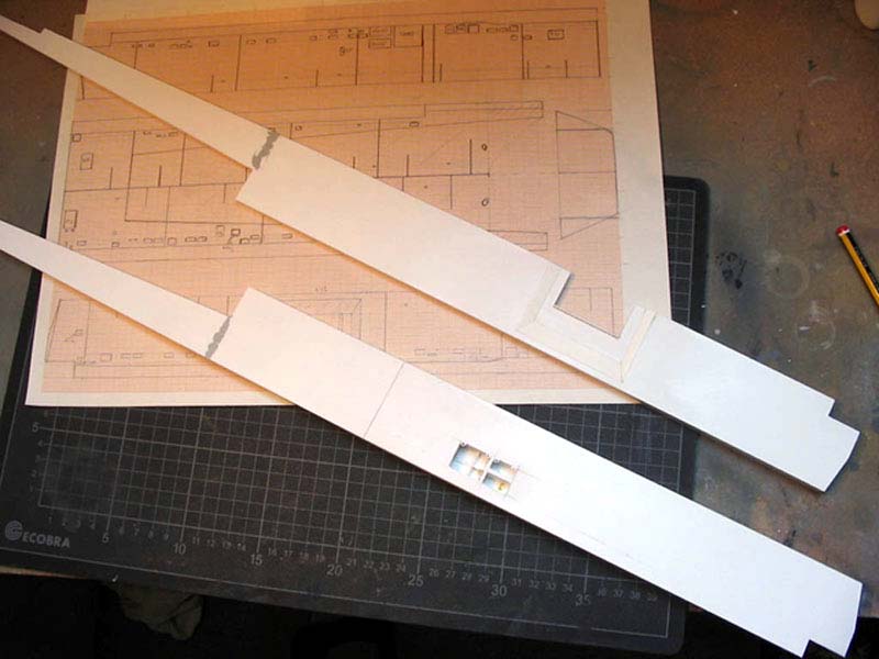
| What you miss are line drawings. To get these I purchased USS Saipan in 1/700 from Dragon and cut the bow-area
into small sectional slices with my razor saw. I copied the form onto paper with a millimetre scaling and
using the graphics-program on my computer mirrored and doubled them to size. Voila! |
 |
|
|
| Ok, ok, ok
. Purists may criticize that I rely on Dragons accuracy using this method. Jup,
I do but up to now nobody said that they got the wrong shape on their LHAs. |
 |
|
|
| The sidewalls were drawn and copied according to the plans and compared with the
smaller Dragon model. Now it was time to start. |
 |
|
|
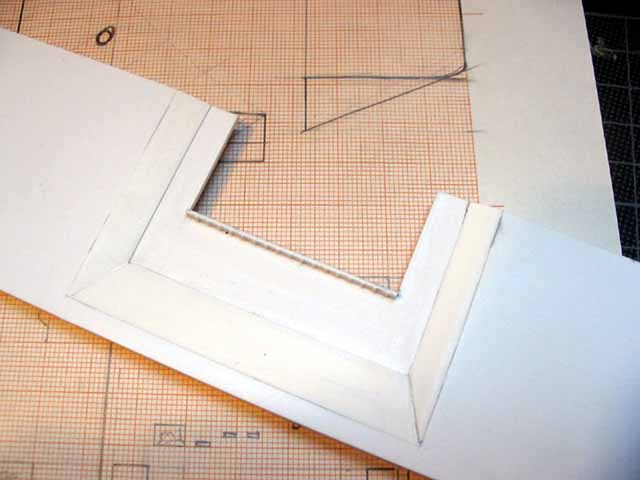
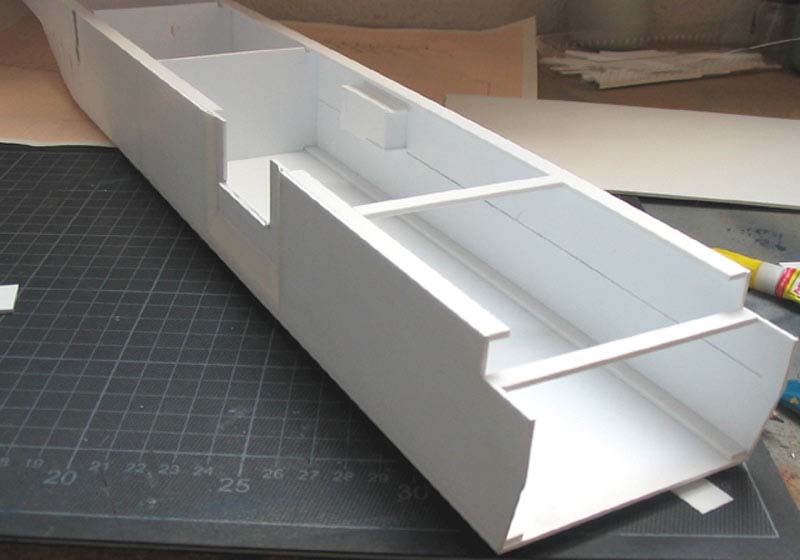
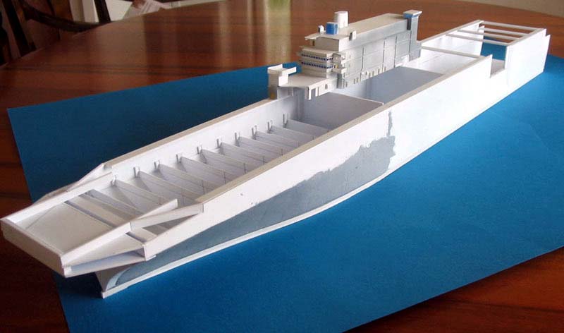
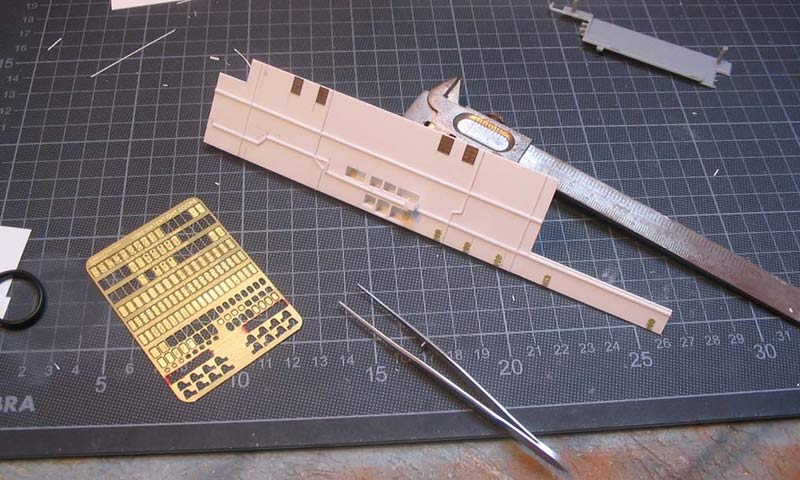
| Building the hull is basically gluing together a shoe box. The sidewalls are made from 1.5mm
styrene sheets, enforced with 3x8mm strips (Evergreen makes a fortune). Each sidewall has a very
prominent opening. On the portside this is the elevator bay connecting hangar and flight deck.
I cut the opening in the sidewall and formed it according to plan and pictures. Everything was
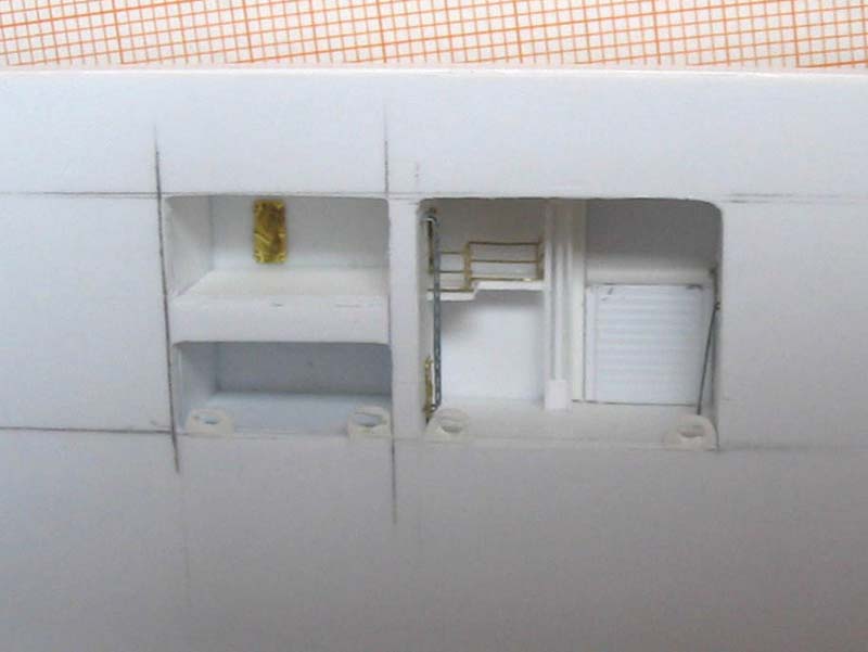
sanded to size, no big deal so far. On the starboard side we have an opening for the unrep-station.
It was built using pictures as reference taken by Charles Landrum. Thanks for the pics, Charles,
they are very helpful! Again I used different sorts of styrene, from 0.75 mm to 1 mm. Doors, hatches
and ladders are standard GMM photoetch from their doors and hatches fret. Later on the unrep-station
will be further detailed with hoses and pump-stations. |
 |
|
|
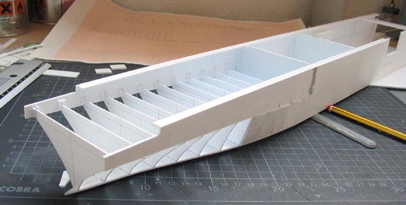
| I glued the sidewalls to a base of 1.5 mm styrene, again backed by 3x6 mm strips in the corners.
I added bulkheads of 1.5 mm to give strength to the construction and avoid warping.
Following the advice of a modelling friend I strengthened the base by laminating a 4mm styrene
plate to the bottom. Now I raised the bulkheads at the ships bow, one by one, leaving 2 cm
gaps between the bulkheads. They were filled with styrene strip, 2mm strength. |
 |
|
|
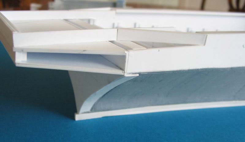
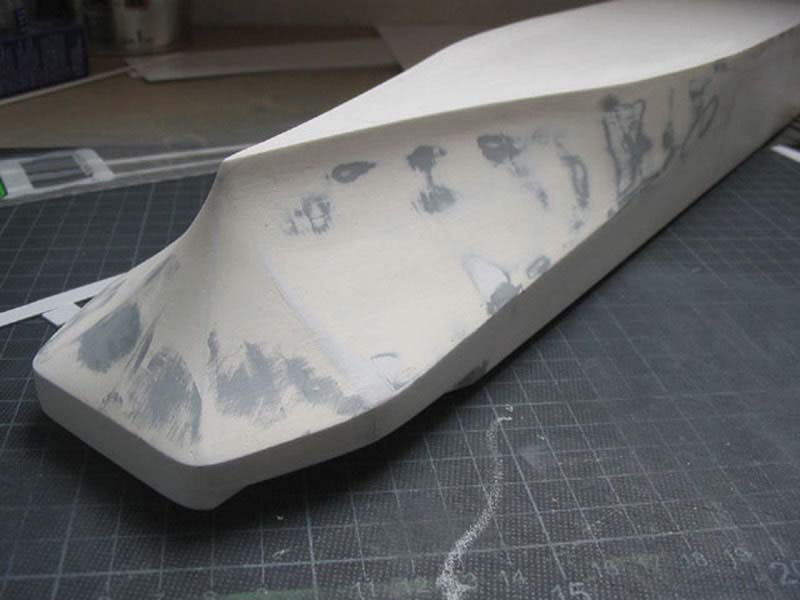
| Everything was set aside to cure for a few days. Then it was time to light my Dremel-tool. I milled
out a rough shape of the bow (use goggles, its a mess) and after a first sanding session with a coarse
sanding paper I applied a coat of Tamiya putty. Again the hull was set aside to cure for a few days.
From that point until today it was a continuous session of sanding and filling, using an ordinary
painters filler, that is easy to sand and gives a smooth surface. To top it off I applied several
coats of spray filler from a can. So far for the hull. |
 |
|
|
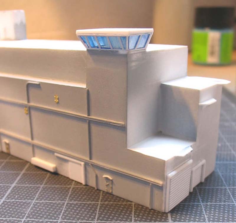
| The very prominent island is basically constructed the same way as the hull. I started with the sidewalls,
cutting them from 1mm styrene sheet. Next step to do was the unrep-station on starboard side, located just above
the one in the hull. I cut the openings drilling holes in the corners first. Then I built the floors,
walls and bulkheads added later. Everything was sanded smooth. Then the plumbing and wiring was added
to the sidewalls as were the doors. The small rain preventers were cut from 0,25mm styrene strips, glued
into place and sanded flat. That done, the sidewalls were glued to the bulkheads for the islands typical
rectangle-form. |
 |
|
|
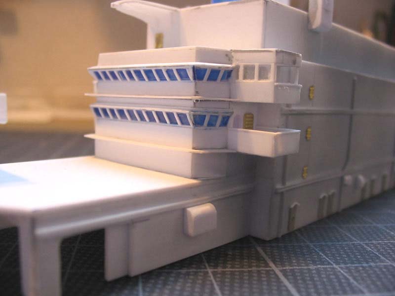
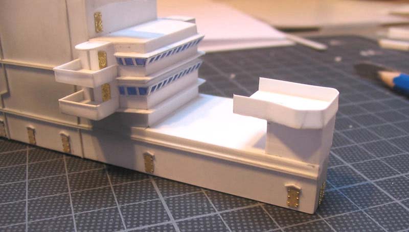
| Enter bridge window rows, a totally different story. I spent nights lying awake and musing over the
right way to do it. At least I came to the following conclusion: First I made a 1:1 drawing of the window
row on paper. Next I taped a piece of clear styrene on the drawing. Pieces of 0.25x0.25 styrene were
carefully glued as frames between the windows and cut to size after having dried. A piece of 0.5x0.25
strip was glued to bottom and top of the rows to make the frames complete. Unfortunately I forgot to
take pics of it. The window rows were painted from inside with Tamiyas transparent blue and glued
into place. Pri-fly emerged from the same procedure. |
 |
|
|
| From various styrene strips I constructed the Vulcan-platform in front of the bridge. And a first
stack was added, using pieces 3x6 strips sanded to shape. No. 2 is to follow. As will the next part of
this buildup feature, dealing with Saipans well-deck. |
 |
|
|