IJN Soryu
in 1/144 Scale
By Bill Waldorf
| Hello again fellow modelers! Well, I am back again with a new report on the IJN Soryu build. If you have been following along in parts. 1 and 2 , I discussed the hull fabrication, the Island and Funnel areas and the Gun Deck areas. In this new article I will go over the construction of the bow and stern decks. I have received a few e-mails asking if I would be more descriptive on the "how to " aspects of the build. I will try and do this although I am not a journalist! Lets go to the photos!! | ||||||||||
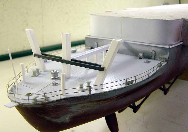
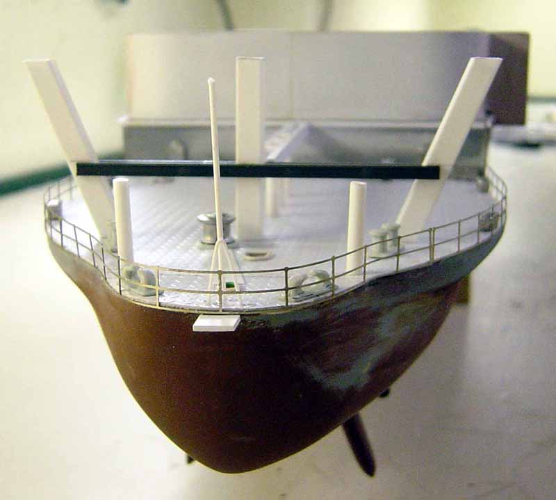
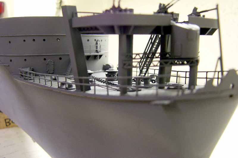
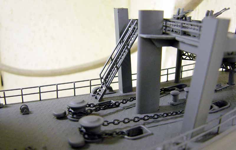
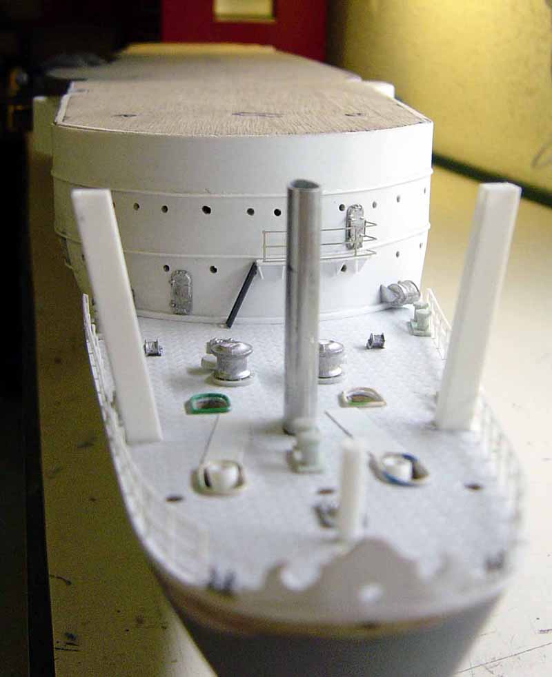
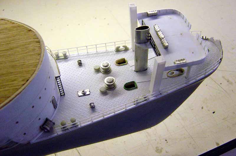
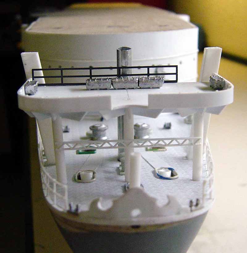
| In the first 3 pics you can see that I am coming along with the bow deck. First I completed the gun deck walls and then I added the diamond plate decking. This diamond plate stuff is available through Plastruct Co. out of California and they have a lot of other things that I will be using on the build. Next I added the forward supports for the flight deck. The center one is formed aluminum and the outer two are styrene plastic square tubing. I then added all of the small details that you see. Cast metal parts are from HR Products. The bollards and fair leads are stolen from the Revell 1/72 Corvette kit as well a the round plates beneath the anchor chain capstans. The anchor hawse openings and the bowline hawse were enhanced with telephone wire. Note the railing on the bow deck. This is fabricated from .025" styrene rod. You can't bend a straight section of P/E railing to conform with the upsweep of the hull in this area so I was forced to make my own. A little thick but I was pleased with the results. Other railing on the front of the gun deck is nickel silver P/E. Vertical ladder from Plastruct again and is N Scale model RR part molded from ABS plastic. Portholes are drilled out with a Dremel Tool at 1/16" dia. Grab rails are .025" styrene rod. |
to enlarge 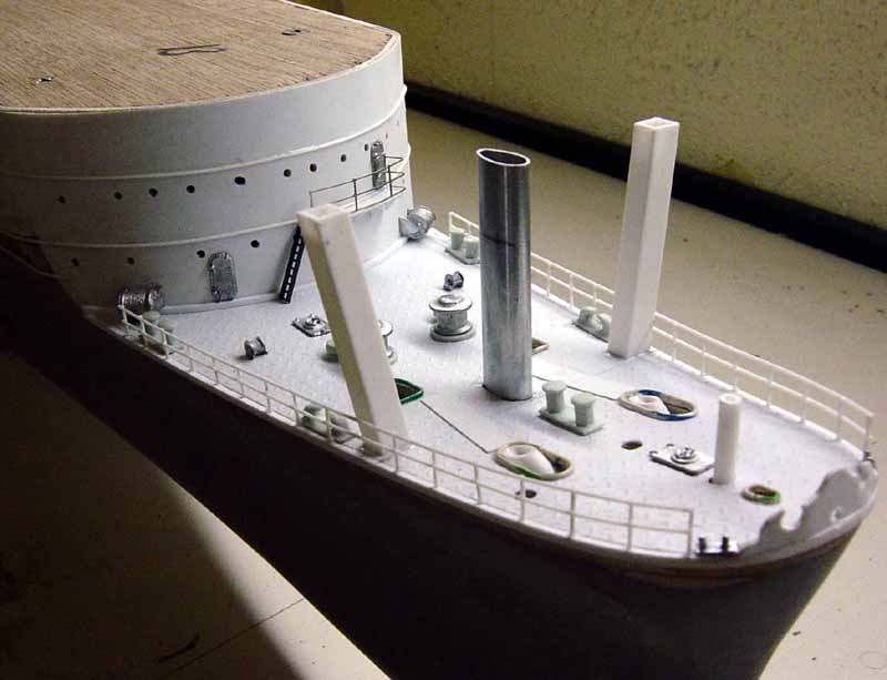 |
|||||||||
 |
||||||||||
 |
||||||||||
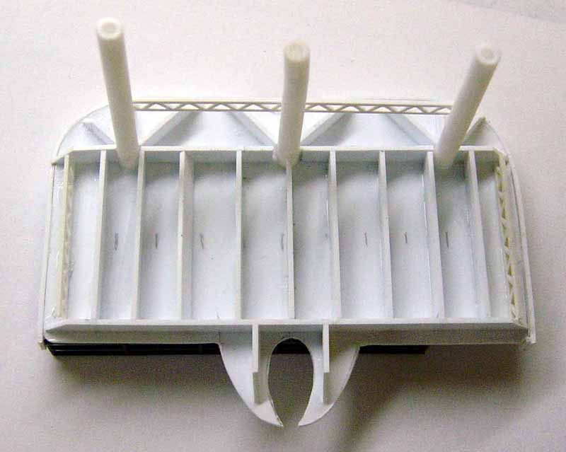
| Here we have the fwd. 25 mm AA gun platform looking from underneath. Note all the bracing which is done with strip styrene. I cut out the main shape of the platform which was taken directly from the plans. I then add either steel walls or railings as applicable to the specific platform. Then the bracing is added as well as any supports that may be needed. I now have a "sub-assembly" which can be mounted in the correct location. All the platforms along the ship are constructed in basically the same manner. These "subassemblies" save a lot of construction time later on. | 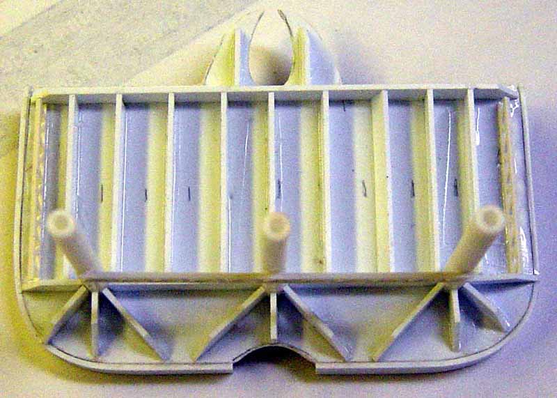 |
|||||||||
 |
||||||||||
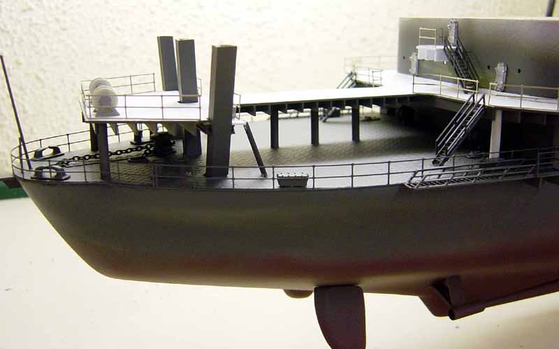
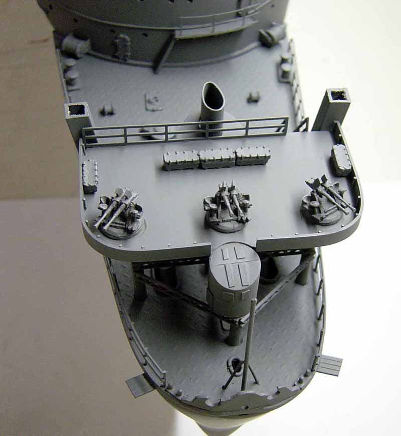
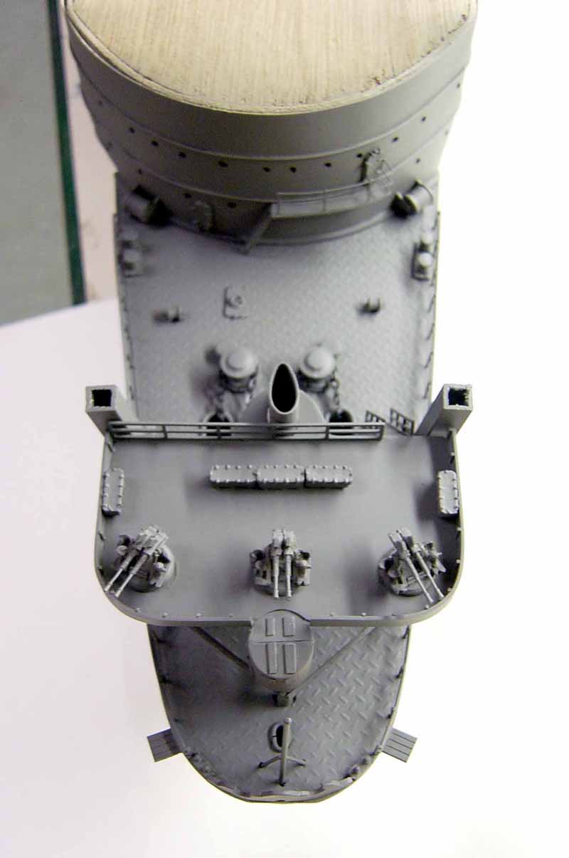
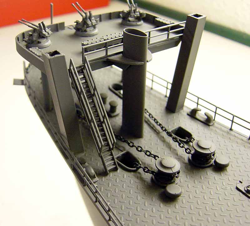
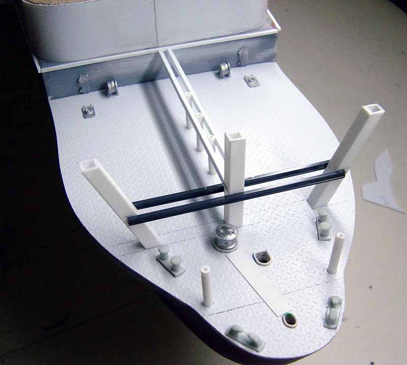
| In this next series of shots you can see I have mounted the fwd. AA platform. The inside of the steel walls around the platform are braced with .025" styrene rod. Railing is from Plastruct again in ABS plastic and is HO scale. RS lockers are cast metal. Note I have not yet added the AA guns or the control tower as of yet. That is coming up!! Truss girder across 3 fwd .supports is also from Plastruct. Comes in 3 '' lengths at a buck an inch!! A bit pricey. | 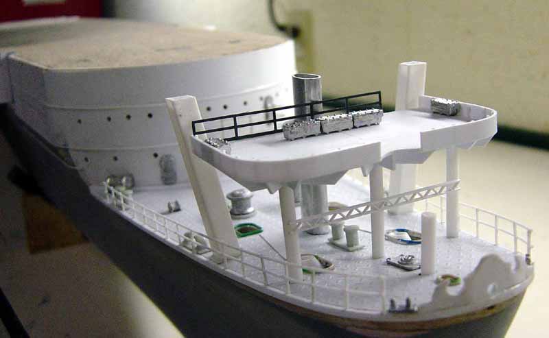 |
|||||||||
 |
||||||||||
 |
||||||||||
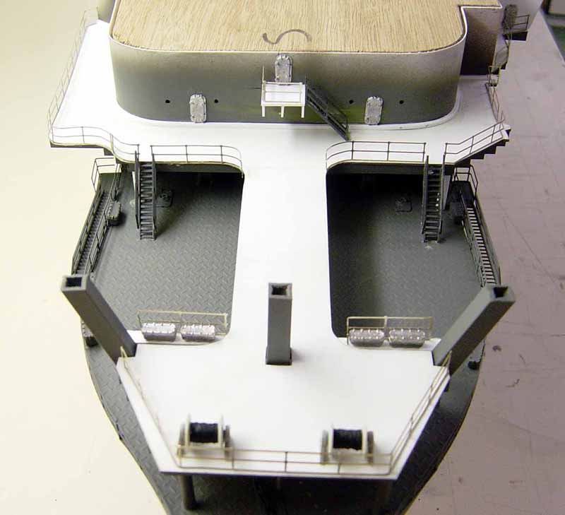
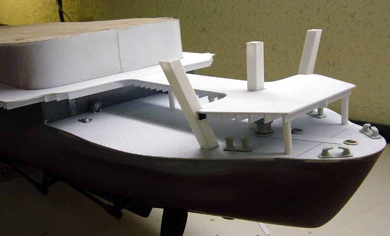
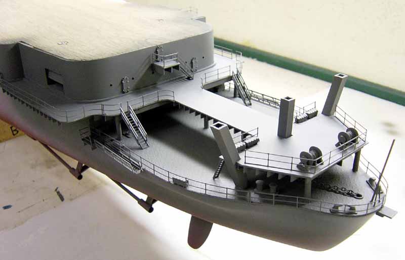
| These next two shots show the beginning stages of fitting out the stern deck. Also known as the boat deck. The same procedure as on the bow deck is used here. Note the diamond plate decking. This is available from Plastruct Co. in different scales. I am using "O" gauge. The pattern matches the one on the plans. Bollards and fairleads are again stolen from the Revell Corvette kit. | 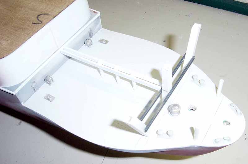 |
|||||||||
 |
||||||||||
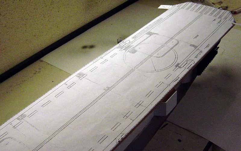
| Here is the upper part of the stern deck. In the first photo you can see the pattern on the right which was cut out directly from the plans. | 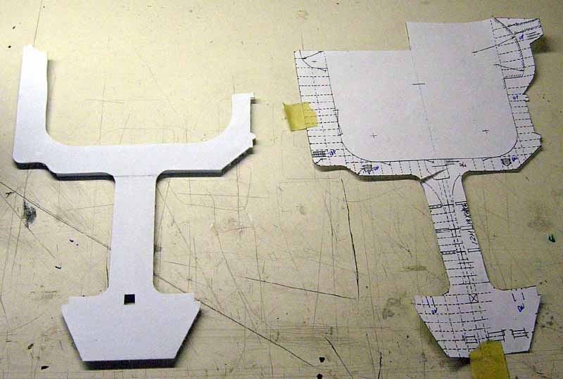 |
|||||||||
| I then transfer the pattern to the material I am using, in this case sheet styrene at .040" thickness. | 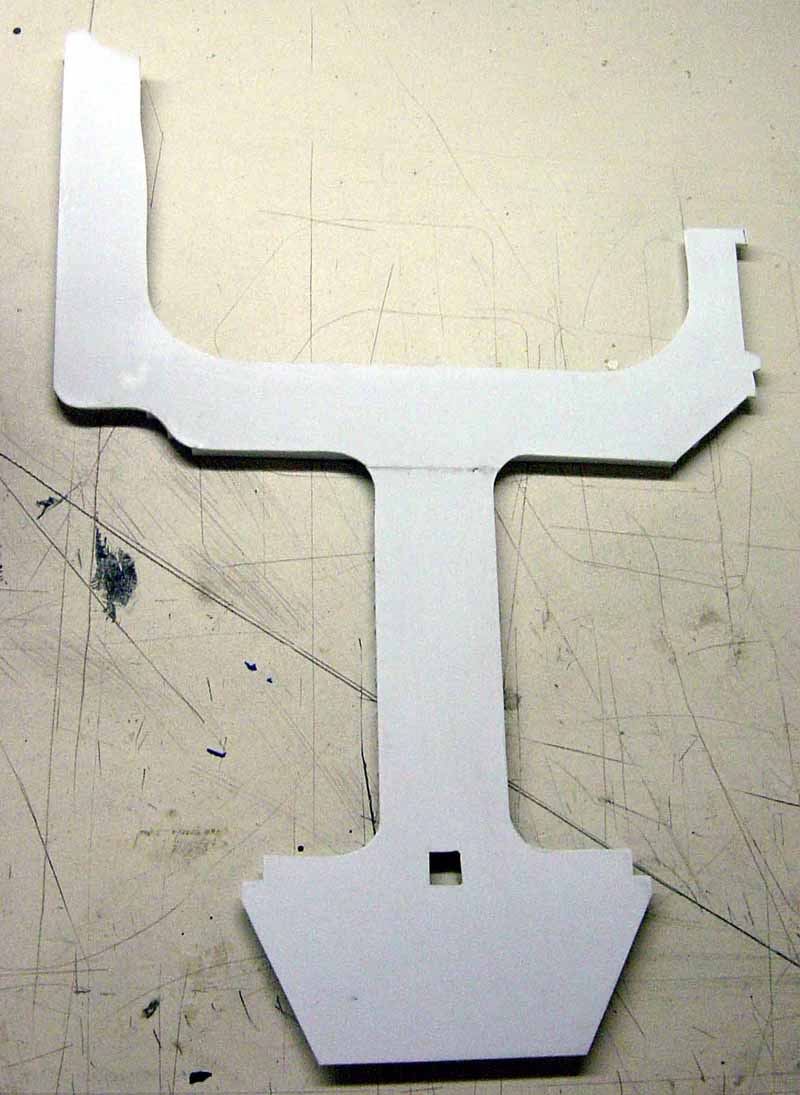 |
|||||||||
| After cutting out the platform and cleaning it up a bit, I then add the bracing underneath. Again, all platforms are constructed using basically the same procedure. | 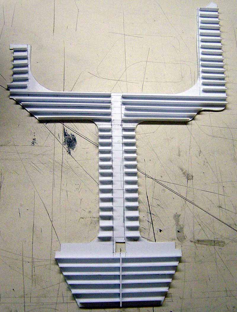 |
|||||||||
| The upper stern deck has been placed in these two photos but not yet permanently attached as I check how things line up. You can see that the bracing I have added underneath the deck adds a lot of interest to the overall picture. | 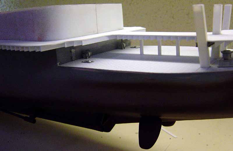 |
|||||||||
 |
||||||||||
| Here is a great little tool if your a scratch builder or even if your not. Cuts plastic, wood, photo etch parts quickly and accurately. Great if you are making a lot of repetitive cuts. Has many other uses too and is a real time saver. Base is made from cast aluminum. The cutting pad is rubber and replacements are available through the Mfg.. Uses single edge razor blades that are easy to change. You can get this tool or one similar through Micro-Mark Tool Co. About $35.00. | 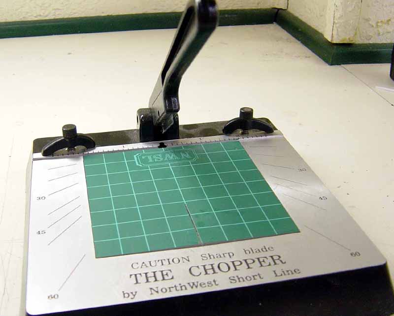 |
|||||||||
This next series of pics show the addition of other details.
Note the P/E railings. These are not brass but nickel silver and are very
well done. Mfg. by James Lane Display Models and are available through
Loyalhanna Dockyard. Other parts are cast metal from HR Products. Cable
reels are stolen again from the Revell Corvette kit and wrapped with thread
to simulate cable. Note in one of the photos you can see the railing on
the aft part of the upper deck just past the two cable reels. This is out
of whack and I have since replaced it after the photos were already taken.
The ships boats which will be mounted on this aft deck area were not here
yet at the time of this article as well as some other parts.
|
||||||||||
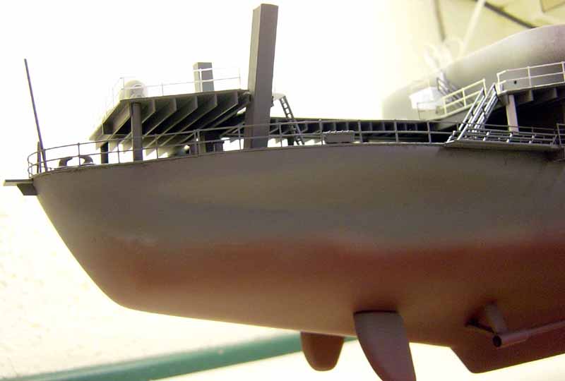
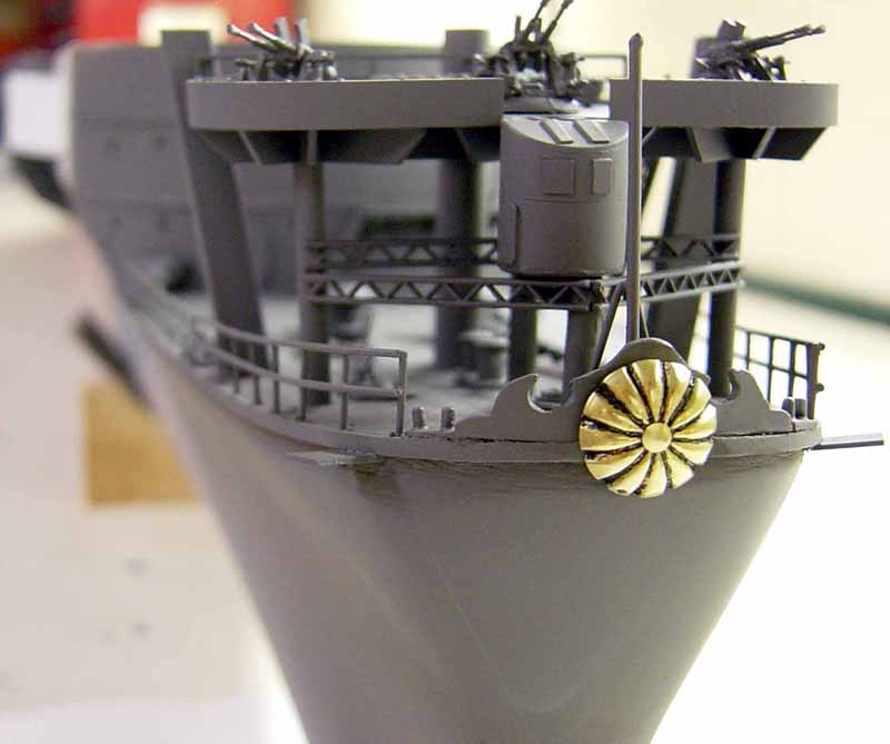
| Back to the Bow deck area. Here you can see most of the details have been added, I am still lacking a few small items, and has been painted. | 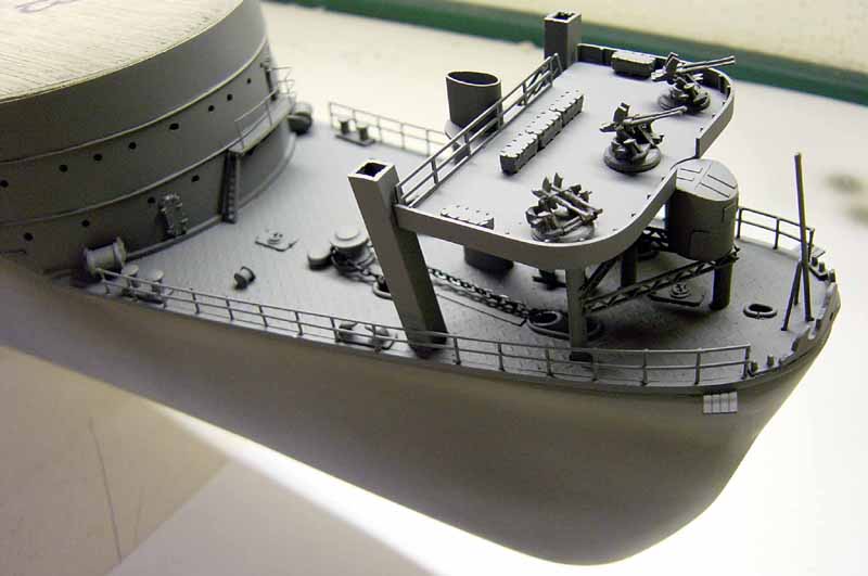 |
|||||||||
|
||||||||||
| Here's the stern deck again mostly completed. As I said before, I'll add the ships boats later on as well as a few more small items. | 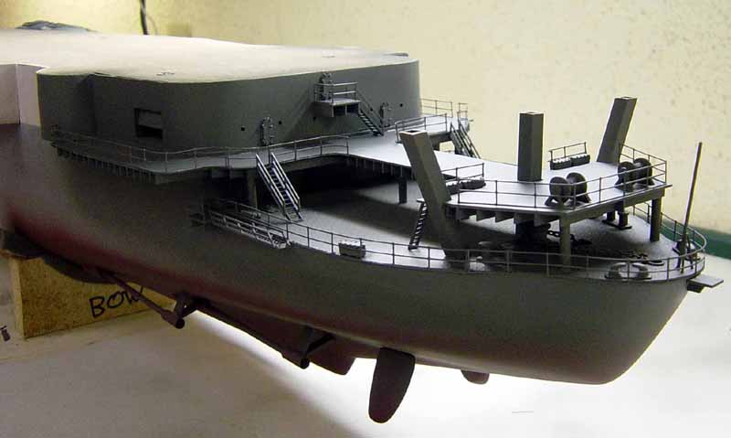 |
|||||||||
 |
||||||||||
| Here is a sneak peek at the flightdeck. More to come on that later on. | 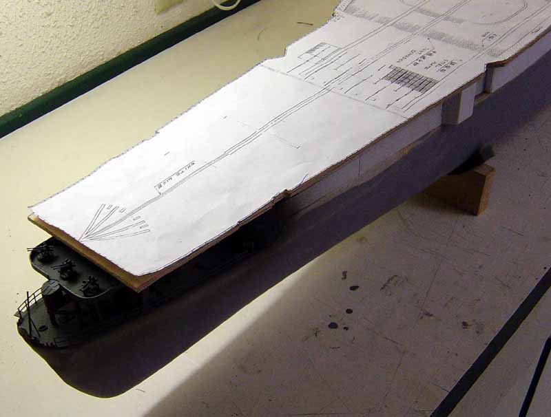 |
|||||||||
 |
||||||||||
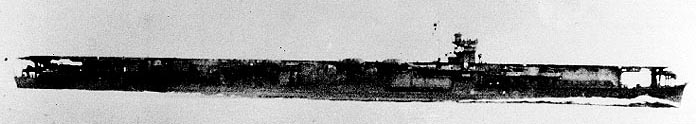
| Full view of ship from portside. | ||||||||||
| Well, that's it for now folks. I hope you all enjoyed the
article. In part 4 I'll start the long task of adding many more parts along
the port and starboard sides of the ship. I am getting there!!
Thanks again to Tim and all the staff at ModelWarships.com. Thanks also to Loyalhanna Dockyard for getting all the fittings for me. A great source if you are into larger scale ships. Any questions anyone has or if I can be of any assistance, please feel free to e-mail me at bjsww@earthlink.net. Stay tuned!!
|
||||||||||

© ModelWarships.com