|
| Background | |||||||||||||||||||
|
Japan had been a signatory of the Washington Naval Treaty of 1922, which, among other things, limited Japanese aircraft carrier tonnage to 60% of that of the United States and Great Britain. She had done so despite a great deal of internal dissension, trying to reconcile the conflicting demands of maintaining parity with the other two powers with a preferred ratio of 70% while faced with the fact that Japan could not successfully compete in an unfettered arms race given her comparatively small industrial base. Though she subsequently re-affirmed the limited ratios with the 1930
London Naval Agreement, Japan had signaled by the end of 1934 that she
would opt out of the treaty come its expiration in 1936. By the time the
treaty expired, Japan had already ramped up its warship building program
to its maximum capacity. In order to expand her carrier tonnage without
overtly alarming the other signatories, and to overcome her limited naval
shipbuilding capacity, Japan turned to a shadow building program, part
of which utilized commercial shipyards and designs that could be quickly
converted to auxiliary aircraft carriers.
|
|||||||||||||||||||
| Design | |||||||||||||||||||
|
Anticipating the need for more Trans Pacific passenger capacity with the arrival of the 1940 Tokyo Olympic Games, and wishing to showcase Japans maritime power, a pair of high speed, luxury ocean liners were planned by Nippon Yusen (the NYK line) in 1937. These ships would join other NYK luxury liners already in service such as the Asama and Nitta Maru classes as Olympic Boats. The new ships were expected to eventually dominate the Trans-Pacific passenger service lines. The decision to build the new sisters was undoubtedly made easier by the internal knowledge that the Imperial Japanese Navy would help financially subsidize their construction. The Navy would do so in return for a design that allowed for a relatively quick conversion to an aircraft carrier, as well as the condition that the Navy could requisition the ship for such a purpose should wartime conditions make it necessary. This was not the first time this arrangement had been utilized. The three Asama Maru class ships had been built under the same set of conditions. Unfortunately, those ships had been unable to meet the ever-evolving naval requirements of size and speed for an aircraft carrier, so they were never requisitioned for conversion. The three following Nitta Maru class ships were also constructed with subsidies and conditions. While they were ultimately converted to the Taiyo class carriers, their own design limitations meant that they werent really capable of anything more than ferry missions. So, there was a pressing need for more capable designs. Accordingly, the Japanese National Diet of 1938 gave budgetary authorization of a 60% building subsidy for the two new ships, Izumo Maru and Kashiwara Maru. The design phase was contentious. Naval requirements dictated a hull of large size and speed, with power to match. NYK concerns were mainly driven by the need to operate economically and to keep the overall budget affordable, even if largely subsidized by the Navy. The power plant was the major point of friction. Up to that time, most Japanese passenger liners, even large ones, had been powered by more economical diesel engines. However, the earlier classes had not been able to generate the acceleration or speed required by aircraft carriers. So, the Navy insisted on steam turbines. A byproduct of the choice of propulsion was ship size: a diesel engine arrangement did not require a hull quite as large as a steam turbine design. Neither design factor was favored by NYK. Ultimately, steam turbines were agreed upon, along with a two -propeller shaft design. A six steam boiler configuration was chosen, with Izumo Maru utilizing Kawasaki-Lamont type boilers and Kashiwara Maru utilizing Mitsubishi type boilers. Not commonly recognized is the fact that both sets of boilers operated at 40kg/420*C, which were extremely high pressures and temperatures for an IJN ship. Even the new, high speed destroyer Shimakazes engines only operated at 40kg/400*C. The steam drove two sets of geared turbines, producing a total of 56,250 SHP to drive the propeller shafts. Also not generally recognized is that the turbines were not repurposed destroyer turbines, but specially designed for these ships. However, the entire power plant was a compromise between merchant and naval service requirements; as such, it weighed considerably more than a comparable naval power plant. Each shaft drove a large, four bladed propeller operating at lower RPMs than typical for an aircraft carrier. This was a departure from the usual three bladed configuration of the time, and both factors were meant to maximize fuel efficiency. The propellers were also the largest ever installed on what would become an Imperial Navy ship, measuring 18ft./5.5m across. To accommodate a conversion to an aircraft carrier, various features were incorporated into the design, including a double bottom , additional fuel oil capacity, aviation gasoline storage tanks forward and aft of the machinery spaces, the installation of a longitudinal bulkhead to separate the turbine rooms, a strengthened main deck, more height between decks, a rearrangement of the superstructure and internal arrangements to ease the installation of aircraft elevators and hangars, more space for additional wiring, and a bulbous bow. Given their merchant origins, it was not possible to add much armor. Two layers of Ducol steel, each 25 mm (0.98 in) thick, protected the sides of the ships' machinery spaces. Their aviation gasoline tanks and magazines were protected by one layer of Ducol steel. In addition, the machinery spaces were further subdivided by transverse and longitudinal bulkheads to limit any flooding. The most unique feature was their bridge and funnel arrangements. Up to this point, the common practice for the Japanese had been to construct a small island structure along with separate funnels that exited the hull just below the flight deck on the starboard side and pointed down towards the water. However, there was a recognized need to further minimize the effect of exhaust gases on air operations, not to mention the effects of an extreme starboard side list on funnel openings close to the waterline. Experiments with a mock-up of Taihos bridge, then also under design at that time, presented a very favorable solution. The design integrated both bridge and funnel, similar to carriers of other nations. The funnel gases were vented upwards as with a typical funnel, only the top of the funnel was canted at a 26* angle outward to starboard, to direct the exhaust even further from the flight deck. Plus, there was the added benefit of enlarged bridge accommodations for the ships command. The design was implemented successfully. The new ships were planned to displace 27,000 tons, and to run at speeds in excess of 24 knots. Final specs were a standard displacement of 26,979 tons and a full load displacement of 29,471 tons, an overall length of approximately 719ft/ 219m, and a top speed of 25.5 knots. The flight deck was sizable. Limitations on top weight meant that the lower hangar of a two-story
hangar design was shorter in height than typical for a Japanese carrier.
This apparently limited the aircraft placed there to fighters only. The
size of the air group suffered and was smaller than comparably sized carriers
such as Hiryu or the Unryus. The air group was set at 48 aircraft with
5 spares.
|
|||||||||||||||||||
| History | |||||||||||||||||||
|
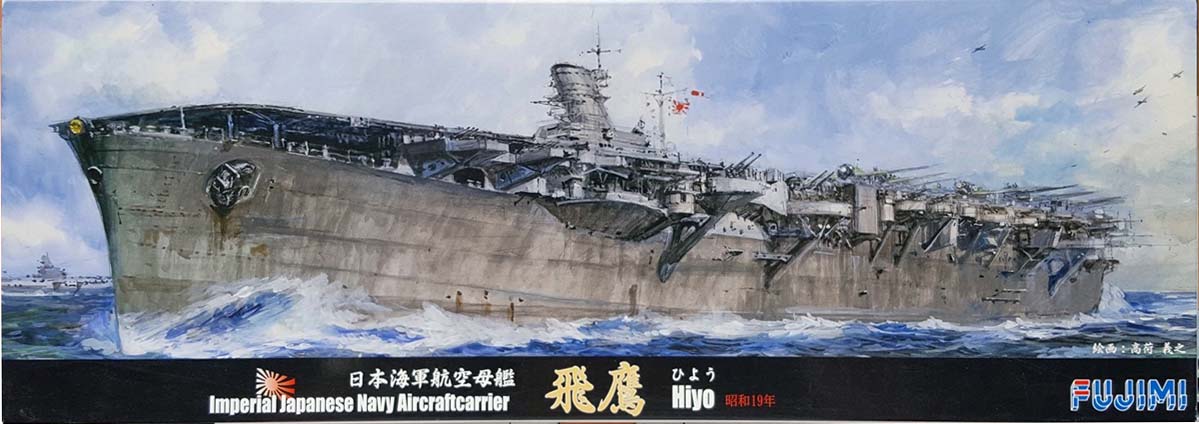
Hiyo ("Flying Hawk") was laid down as the fast luxury passenger liner Izumo Maru for the Nippon Yusan Kaisha line on November 30, 1939 at the Kawasaki Heavy Industries Shipyard in Kobe, Japan. She was built on the slipways just vacated by the aircraft carrier Zuikaku, launched a few days earlier on November 27th. She was purchased by the Japanese Navy for completion as an aircraft carrier on February 10, 1941 while still on the ways. Izumo Maru was launched on June 24, 1941, and commissioned as Hiyo on July 31, 1942. Initially expected to be designated as an auxiliary aircraft carrier, the disastrous loss of four fleet type carriers during the previous month at Midway led to a reassessment of her designation by the IJN. Hiyo and her sister Junyo were both declared regular fleet carriers and renamed as warships. They became the second division element of the IJNs carrier strike force known as the First Air Fleet, along with the first division ships Shokaku and Zuikaku. Hiyo was subsequently designated flagship of CarDiv 2 under Rear Admiral Kakuji Kakuta. Hiyo spent two months working up in the Inland Sea, and subsequently joined Junyo at Truk in early October as part of the Combined Fleets effort to dislodge American Forces at Guadalcanal. In the preliminary actions of the Battle of Santa Cruz, CarDiv 2 sortied from Truk in the company of the Advance Force. It was intended that the air groups would provide air cover over Guadalcanal during efforts to retake Henderson Field. Initially, Division 2s aircraft conducted scouting and anti-submarine patrols. Then, on October, 17, CarDiv 2 launched its first combat air sortie, a combined airstrike of 36 aircraft (18 B5N2s carrying 800kg bombs and 18 A6M2s for escort, split evenly between Hiyo and Junyo) to attack American transports off Lunga Point on Guadalcanal. The airstrike turned disastrous. A vigorous defense by two USN destroyers and the Cactus Air Force on Guadalcanal led to the loss of over half the bombers for minimal American losses and minimal damage, if any, to shipping. Four days later, with CarDiv 2 and the Advance Force still operating to the north of Guadalcanal, Hiyo suffered another misfortune. In the late afternoon, a fire broke out in her starboard generator room. The fire was extinguished after 90 minutes, but her condenser was damaged. Hiyo was unable to make more than 16 knots, insufficient speed for battle conditions. Admiral Kakuta transferred his command to Junyo, along with three A6M2s, one D3A1 and five B5N2s from Hiyo to replenish Junyos air group. The rest of Hiyos air group transferred to Rabaul, to participate in the battle from that land base. Hiyo then retired to Truk on her port engine for temporary repairs. Ultimately, she returned to Kure, Japan in December for permanent repair. (Editorial note: In hindsight, Hiyos premature retirement from battle was a fortuitous turn of events for the Americans. After airstrikes from CarDiv 1 left Hornet dead in the water and Enterprise damaged, Junyo launched her own airstrike on USS Enterprise, then the sole operating US carrier. The attack did not damage Enterprise any further. Loss of the Hiyo air group had meant an attack by an unbalanced airstrike of smaller mass. A larger strike force would most likely have more effectively endured CAP attacks and further incapacitated Enterprise, or worse. The Japanese would then have been in a position to capitalize on the Americans lack of mobile air power, prolonging the fight over Guadalcanal with ever spiraling losses on both sides.) Hiyo exited drydock at the end of December, 1942 upon the completion of her repairs. She spent time training on the Inland Sea, and re-entered at Kure at the end of February for additional AA, improved AA directors, and an additional Type 21 radar emplaced on the port, aft end of her flight deck, on a retractable mount. Its worth noting that her air group had continued to support operations around Guadalcanal from Rabaul until late December, when it rejoined the ship in Japan. Hiyo rejoined Junyo and CarDiv2 at Truk in March, 1943. The next two months were spent in operations to support the reinforcement of Rabaul (Operation I-Go) and the evacuation of the Aleutians. Hiyo returned to Japan in June. Outside Yokosuka harbor on June 10th, Hiyo was torpedoed by USS Trigger. Two hits on the starboard side caused severe flooding and loss of power, but Hiyo eventually made it back to Yokosuka under her own power. Repairs were completed in mid-September. Her AA suite was further bolstered with additional single and triple 25mm mounts. Her air group, along with that of light carrier Ryuho, was sent on to Singapore for extended training at the beginning of October. Hiyo and Ryuho eventually joined up with their respective air groups at Singapore by early December, 1943. Unfortunately, both air groups were then again divorced from the carriers to fight at Rabaul, where they incurred 50% losses. In the meantime, Hiyo spent the next month on aircraft ferry duty between several South Pacific locations, arriving back at Kure at the beginning of January, 1944. She remained in the Kure area for another four months while continuing to train yet another reconstituted air group. In May, she departed with other units for forward staging at Tawi Tawi in the Phillipines. Hiyos demise came on June 20, 1944 during the Battle of the Philippine Sea. As part of CarDiv 2 (Junyo, Hiyo, Ryuho) with Admiral Ozawas Force B, she had already launched two strikes the previous day with minimal results and high losses. All of the Japanese forces were withdrawing to the west, expecting to regroup for new attacks the following day. Scouts from US Task Force 58 had searched fruitlessly all day for the Japanese. A mid- afternoon sighting prompted an all-out late afternoon attack by the Americans. Learning of the approaching enemy aircraft, Hiyo turned into the wind to launch two B6N Tenzan smoke screen aircraft. However, doing so left her 6,000 meters behind Junyo and relatively exposed. Several bombs and at least one torpedo struck her during the ensuing attack. Hiyo took on a slight list, maneuvering on one engine. Eventually, she stopped dead in the water with a 9* list to starboard, though she was not then in imminent danger of sinking. Nagato was ordered to take her in tow. Unfortunately, gasoline vapors from cracked aviation gas storage tanks permeated the ship, and just after 1800 hrs., Hiyo was rocked by an enormous gasoline vapor explosion which doomed the ship. Burning fiercely and settling quickly by the stern, she sank a little more than an hour later. Approximately 250 men were lost, but over 1,400 of her crew were rescued by the escorting destroyers. (Note: Background, Design and History are reprised from the Hasegawa 1/350 Hiyo 1942 kit review of December, 2017.) |
|||||||||||||||||||
| The Kit | |||||||||||||||||||
|
Prior to the release of Fujimis Hiyo class kits, Tamiya was the only company offering a Hiyo class kit in 1/700 scale, that of the better-known sister ship, Junyo. Tamiyas kit dates back to the original 1/700 Waterline Consortium kits releases in the early 1970s. That said, this kit exemplified the best of those original releases, is still in production, and remains a viable kit today. Personally, I consider it Tamiyas best kit from the era, making it perhaps the best of all those early kits. |
|||||||||||||||||||
|
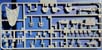
It is sharply molded with an abundance of good details, including a degaussing cable with brackets, sharply delineated sealed porthole covers, detailed elevator wells (still the best rendition of elevator wells in 1/700 styrene from any kit maker for 45 years and counting), nicely scaled flight deck planking (raised, not recessed), shallow trenches for the flight deck safety barriers, sharply molded deck treading and mooring bits on the forecastle and stern boat deck, and an assortment of conduits on the superstructure. I recall that some of the 12.7cm mounts could be made to turn as well, though thats not necessarily an advantage to some. Of course, it also has some less than desirable characteristics typical of that era of modeling: raised flight deck marking lines, molded on arrestor wires, solid sponson supports, and older, less defined weapons and accessory parts. The other shortfall for some is that Tamiya has never bothered with offering a kit of sister ship Hiyo. Given the relative simplicity of revamping the kit by deleting some parts and replacing the mainmast, this has always been a puzzling omission. The fit of the Tamiya Junyo kit is its final, 1945 as-surrendered configuration, long after it had participated in all of its meaningful operations. This includes changes made after repairs to damage incurred at the Battle of the Philippine Sea, and her torpedoing in December, 1944. The Junyo kit has been attractive enough to be supported by numerous aftermarket PE and wood flight deck sets. Notable among them are immensely comprehensive upgrade sets from Artist Hobby and Five Star. The Five Star set includes a fully detailed brass flight deck. Even FineMolds release a special mixed set of its Nano-Dread accessory parts in 2013 for this kit. Whether due to the gap in the 1/700 IJN offerings for this class, and/or a desire to update the class in kit forms, Fujimi chose to kick off their own kits of the Hiyo class by releasing a Hiyo kit in 2016 in its 1944 (Battle of the Philippine Sea) fit. There have been a few variants released since then a 1942 fit, a full hull version, the inclusion of a comprehensive photo etch set, options for a full hull with a comprehensive photo etch set, and a kit with additional aircraft. Also offered are several 1942 versions of Junyo with the same various accessories. I was curious about the kit when it was released, though not enough to actually purchase one. However, a recent sale by HobbyLink Japan made it hard to ignore for approximately $16. I mean, really, how could I not buy one at that price? My review kit is the original 1944 kit in its basic form. It includes over 300 parts held on twenty sprues. The kit is very sharply molded in gray styrene plastic with a clean, matte finish and no soft edges or details. The details certainly seem molded to a sharper degree than the Fujimi fleet carriers that were released earlier that I have in my stash (Kaga, Taiho, Shokaku, Zuikaku). There was no flash or sinkholes whatsoever on my sample. The sprue breakdown is as follows:
|
|||||||||||||||||||
| Sprue A Hull, Starboard half | |||||||||||||||||||
|
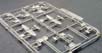
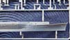
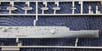
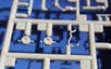
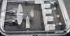
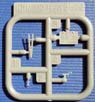
This is a waterline kit, and the hull is split longitudinally into two halves, with each connected to a separate sprue. I have to say, the hull is beautifully rendered, with wonderfully sharp detailing. The styrene appears a touch harder than what I typically see for a Fujimi kit, allowing for a higher degree of fidelity for all the molded details. The degree and level of detailing is impressive: anchor recesses, hawseholes, portholes (open with eyebrow high up and sealed covers for several lower down correct for 1944), a degaussing cable with brackets, several prominent air intakes with molded screens along the hull, a large, starboard side sponson that helped support the island, some smaller sponsons, some hatches and small air intakes, a number of small equipment boxes, assorted small piping and conduits, and a couple of very small platforms with support trusses. Its a great looking hull. The hull interior has multiple mounting points for internal styrene bracing rods that helps connect the hull halves together in a rigid stance. Also included on the sprue are the landing light arrays and all the small platforms that ring the flight deck. Many come with equipment boxes and access ladders molded on. Interestingly, none of these platforms have molded on sidewalls, which is actually correct. The platforms were edged with railings, and covered with canvas dodgers as needed. (This was true of all the Japanese aircraft carriers.) These platforms also have small indents in their flooring, meant to represent perforated flooring for drainage. Its not quite the same as a photoetch representation, but these holes do evoke that type construction. There are no real nitpicks here. Fujimi did mold on the paravanes, rear anchor and a life ring, but they are pretty sharp. Theres no hull plating, but I think that more appropriate for 1/700 scale. The hull scales out essentially correct. Hiyos particulars versus the
scale and kit:
*because the hull is split in half, this measurement is only an estimate.
However, I did use digital calipers to measure the components and I think
the estimate to be accurate.
|
|||||||||||||||||||
 |
|||||||||||||||||||
| Sprue B | |||||||||||||||||||
|
This sprue is composed of twenty 3mm diameter rods of varying lengths that are glued to both hull halves from the inside. Eight of the rods are not used in any of Fujimis Hiyo/Junyo kits. I did wonder about this. Im guessing that perhaps this is a generic set of connectors used in several kits. |
|||||||||||||||||||
| Sprue C Hull, port half | |||||||||||||||||||
|
Ditto all my comments on Sprue A. Here, the sprue carries all the ship boats instead of the platforms
for the flight deck. This was unexpected, as Fujimi has already created
(and separately sold) a number of dedicated sprues for ships boats. While
it may be that these versions are based on the same CAD drawings used elsewhere
and relocated to this sprue, these have the look of something that has
been tweaked. All come with boat chocks molded on. The 9m cutters have
oars set on top of the seat thwarts, which is a nice touch, though hard
to paint. I still dont care for their versions of the 13m daihatsu as
the upsweep of the bows and bow ramp still seem far too pronounced to me.
The 12m motor launches are extremely nice, with well defined windows and
deck planking. The main anchors are also located here. These are particular
good, even showing tiny lightening holes (or maybe channels) in the flukes.
|
|||||||||||||||||||
 |
|||||||||||||||||||
 |
|||||||||||||||||||
| Sprue D | |||||||||||||||||||
|
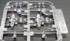
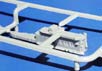
This one contains the hidden hull bottom plate, the stern boat deck, elevators, elevator wells and spacers for configuring a raised elevator within the well, the forward hangar deck bulkhead, and a platform for the aft hangar deck bulkhead. The detailing of the boat deck is notable. Its sharply molded with very nicely scale metal deck treading, mooring bits, detailed turntables and two sets of rails for the aircraft engine test stands. Sadly, the wells are fully enclosed and only one story high, the same as with the other Fujimi IJN carrier kits. Still, the elevator well walls have sharply defined guide tracks for counterweights (not included). These wells are certainly better than those on the other Fujimi fleet carrier kits that Ive seen. Interestingly, the sprue guide indicates that a forecastle deck was
supposed to be included here. But, mine was clearly clipped out before
enclosed in its packaging.
|
|||||||||||||||||||
 |
|||||||||||||||||||
| Sprue E x 2 | |||||||||||||||||||
|
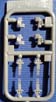
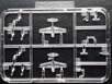
This is one of Fujimis common IJN weapons sprues. A small sprue, it holds just four of the twin 12.7cm40cal main AA batteries. The mount is comprised of two pieces, the actual mount and the twin barrels. Only six mounts are utilized for this class of aircraft carrier. The detailing is nice, and the parts serviceable, but there are better
versions out there from Fine Molds (NanoDread line) and PitRoad (NE line)
|
 |
||||||||||||||||||
| Sprue F | |||||||||||||||||||
| As with E, this is a Fujimi common sprue, though for the triple 25mm AA mounts. Each mount is a one-piece unit. Ive never really cared for the Fujimi version, as the barrels are clearly too long, a bit thick and set too closely together. Again, better styrene versions are available from Fine Molds and PitRoad. A third issue specific to this kit is that the triple mounts aboard these ships gained a splinter shield by 1944 and this kit does not provide for these. I do note that Fujimi has recently (in February 2019) released an updated version of the kit with a new, two-piece 25mm mount that includes a splinter shield. |  |
||||||||||||||||||
| Sprue G | |||||||||||||||||||
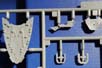
|
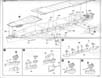
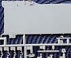
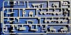
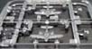
The flight deck is molded in two large adjoining sections. This sprue holds the much larger aft section, which also includes the metal plated stern section with the round-down. Sprue N holds the bow section and is addressed separately below. Additional to this sprue are some boat davits, some access ladders, a jack staff, flight deck support pillars, some searchlight and lookout platforms, an underdeck storage compartment for the aircraft crane and a couple of other under the flight deck pieces that I do not recognize. Fujimi has provided a lap joint on the underside of the flight deck to join the two sections together. The aft section has the recess set into its forward end while the bow section provides the extension (seen on Sprue N.) When seen from above, the seam wisely occurs along the line of a cross-deck channel that holds one wire of a flight deck safety barrier. So, it appears that the seam will be well hidden, with no gaps to fill in the deck planking. The adjoining ends are squared off, and the planking lines do line up, so one can hope that a good, tight fit materializes without an overwide channel. The flight deck itself is nicely executed. In fact, I would say that its a clear improvement over Fujimis past efforts (at least for the fleet carriers, as I dont have any of their smaller carriers to compare it to). While the planking width hasnt changed from Fujimis standard of .020 in 1/700, the seams appear finer and less recessed and, even better, the planking pattern has been altered. Now, the pattern alternates every third plank instead of every second plank. Along with the more subtle seams, the planking has a less distracting, more pleasing appearance. It may not match the accuracy and execution of Flyhawks 1/700 deck planking, but its far better than what came before from Fujimi. Detailing on this portion of the flight deck includes open rain gutters along the aft end of the deck, subtle outlines for the paired bases of each arresting wire, more recessed channels for the wire cabled cross-deck crash barriers and the anchoring struts used to raise and lower them, and small extensions along the deck for small lights denoting the flight deck perimeter. There are also recesses for a hide-away 110cm searchlight and the aft Type 21 radar module, plus a large aperture for the aft elevator. Lastly is the girder grid arrays that are placed to either side of the flight deck round down that held various signal lights to help keep landing pilots within the landing groove. Dimensionally, the flight deck is quite accurate. Actual versus scale
and kit dimensions:
*each section measured independently and added together
|
|||||||||||||||||||
 |
|||||||||||||||||||
 |
|||||||||||||||||||
| Sprue H | |||||||||||||||||||
|
Fujimis common single 25mm AA sprue. According to the instructions, three are used on the island structure. Some portable mounts were also deployed on the flight deck while the ship was in port. Fujimis version is ok; its certainly rendered better than its triple barreled counterpart. Still, FineMolds own offering is the styrene standard bearer for this type mount. |
 |
||||||||||||||||||
| Sprue K | |||||||||||||||||||
|
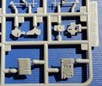
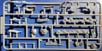
This sprue is a mix of small but critical components. Included are all four of the radio antenna masts, numerous support columns for most all of the 12.7cm main battery and 25mmAA sponsons, also for a searchlight sponson, two Type 94 High Angle directors for the main battery, the bulkhead for the aft portion of the hangar, several small platforms attached to the hull and for the bridge, navigation/lookout sponsons mounted on the hull, the auxiliary piping for the funnel, a light platform that wraps around a portion of the funnel, an RDF loop antenna, the Type 21 radar unit that sits atop the island, and the two halves of the funnel. All parts are nicely formed, though, obviously, photoetch replacements
for the radar and aerial masts is always a consideration.
|
|||||||||||||||||||
 |
|||||||||||||||||||
 |
|||||||||||||||||||
| Sprue L | |||||||||||||||||||
|
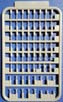
This sprue is devoted to sponsons and platforms. Included are several for the triple 25mm mounts along the hull, and three for the 12.7cm HA main battery mounts. Most everything else is either a simple platform or hull mounted sponson. Most surfaces have nicely detailed treading and support trusses on the underside surface. The 12.7cm sponson platforms show display some wood plank flooring surrounding the base ring. |
 |
||||||||||||||||||
 |
|||||||||||||||||||
 |
|||||||||||||||||||
| Sprue M | |||||||||||||||||||
|
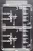
This is one of four aircraft sprues, here devoted to the Nakajima B6N2 Tenzan attack bomber. (Known as Jill in Allied identification parlance, the Tenzan was the replacement for the earlier B5N Kate, and could carry an aerial torpedo or bomb externally.) Molded in clear styrene, the aircraft is a one-piece unit, with separate canopy and tail wheel, propeller, landing gear, and external bomb load. The aircraft has obvious panel lines, and the distinctive cowl hump of the air intake as well as the swept forward vertical stabilizer/rudder. Only two are included with the kit. |
 |
||||||||||||||||||
|
|||||||||||||||||||
| Sprue N | |||||||||||||||||||
|
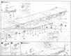
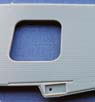
This holds the forward third of the flight deck, two small rectangles to depict the flight information blackboards for the side of the island, and a support member for the underside of this section of flight deck. As with the aft section, the planking is as previously described, a rain gutter borders the metal plated portion of the deck while a thin, plain styrene band borders the planked portions, there are more small platforms for deck edge warning lights, and there is an aperture for the forward elevator. Theres also a finely detailed windscreen depicted in the lowered position on the flight deck in its recess, and the other safety barrier. Interestingly, there is no windscreen and recess molded separately as
with Fujimis prior fleet carrier kits. One point of differentiation between
the two sister ships was the shape of the front corners of the bow section
of the flight deck. Junyos was sharply angled, while Hiyos had small
curves. This kit accurately reproduces those arcs, though they are nearly
inconspicuous in this scale.
|
|||||||||||||||||||
| Sprue PA | |||||||||||||||||||
|
The second aircraft sprue, this consists of two Mitsubishi A6M2 Model 21 Zero fighters. (These were early model Zeros converted to a fighter bomber role late in the war and carried aboard the shorter IJN carriers.) As with the Tenzans, they are molded in clear styrene as one-piece units, with separate propeller, landing gear, two external drop tanks, and clear panel lines. However, these planes are molded with their canopies and tailwheels in place. Also odd is that the instructions allude to carrying a 250kg bomb, but no provision is made for that. The external drop tanks are provided for instead. |
 |
||||||||||||||||||
 |
|||||||||||||||||||
| Sprue PB | |||||||||||||||||||
| Another aircraft sprue, this one holds two Aichi D3Y1 Model 22 Val dive bombers. Like the Type 21 Zeros, they are also molded in clear styrene as one-piece units with the canopies and tailwheels in place, as well as a separate propeller, landing gear with spats, external bomb (250K) load, and clear panel lines. | 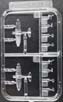 |
||||||||||||||||||
 |
|||||||||||||||||||
| Sprue PV | |||||||||||||||||||
| The last aircraft sprue, this one hold two of the Mitsubishi A6M5 Type 52 late model Zero fighters. These are molded in the same manner as the Tenzans, with separate canopies and tailwheels. Again, clear styrene is used and there is a separate propeller, set of landing gear, and drop tank. | 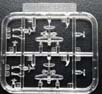 |
||||||||||||||||||
 |
|||||||||||||||||||
 |
|||||||||||||||||||
| Sprue Q | |||||||||||||||||||
|
This is a small sprue holding an emergency rudder, the trailing legs of the tripod mainmast, a conduit pipe for the island, along with a bench that sits at the base of the bridge island. The detailing on the rudder is notable, while I find the tripod legs typically stubby. |
 |
||||||||||||||||||
| Sprue S | |||||||||||||||||||
| This is one-piece sprue containing the funnel grill. Its typical for styrene, and replacement by a photo etch replacement would be preferable. | 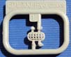 |
||||||||||||||||||
| Sprue V | |||||||||||||||||||
|
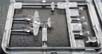
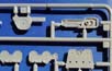
Another limited sprue, this one carries the bridge and a truss structure for supporting the canted funnel on its starboard side. This bridge is essentially one piece, with only the compass bridge deck and roof, funnel, and ancillary equipment/platforms/piping, etc. molded separately. Its extremely well done and sharply molded, with access apertures, portholes, conduits, ladders, and other details. The only nitpicks are some small, featureless hatches and one Aztec type ladder molded on. The two truss supports on the sprue are nearly identical. Only one has what appears to be a signal light molded on the outside, and this one is designated for use on Hiyo. I imagine the other is meant for Junyo. |
|||||||||||||||||||
 |
|||||||||||||||||||
| Sprue W | |||||||||||||||||||
|
This is a new common sprue for Fujimi, the optical equipment sprue. (Its also offered for sale separately.) It includes numerous 12cm search binoculars, searchlight directors, small rangefinders, 25mm AA directors, 110cm main searchlights, and 30cm signaling searchlights. |
 |
||||||||||||||||||
| Sprue Y | |||||||||||||||||||
|
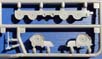
This sprue carries the forecastle deck, several sponsons for the 12.7cm twin main battery mounts, several sponsons and platforms for the triple 25mm AA mounts added later in the war, additional crews quarter compartments for the stern 25mm AA platform, the compass bridge deck roof/AA command platform for the bridge, also the bridge window and a an upper frame for them, the components of the bridge mast, some other small bridge platforms, some platform supports, two Type 21 radars and mounts, a 25mm AA director, and the small maneuvering indicator light mounted at the stern. The detailing is very nice, particularly on the forecastle deck, though
it has molded-on hawser reels. Like those pieces located on Sprue L, the
12.7cm sponson platforms show display some wood plank flooring surrounding
the base ring. If possible, the radars and maneuvering light are best replaced
with photo-etch versions. The Type 21 radars are more compact than the
bridge mounted unit on Sprue K, as one of these units was set on a retractable
platform to clear the aft flight deck where it was positioned.
|
 |
||||||||||||||||||
 |
|||||||||||||||||||
 |
|||||||||||||||||||
| Decals | |||||||||||||||||||
| This is a small sheet with flight deck lines, warning stripes, red and white round down panel, red Rising Sun rondels for the aircraft, and some IJN flags. There are no registration issues | |||||||||||||||||||
| Instructions | |||||||||||||||||||
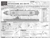
| These come on one very long sheet of paper, printed front and back
in black and white, segmented into multiple panels. sections. Interestingly,
the parts breakdown is printed on a separate sheet of paper.
Its clearly illustrated, and labeled in Japanese. Assembly is shown step-by-step via exploded, three-point perspective illustrations. Sub-assemblies are shown in good detail, and the construction process appears straightforward. |
 |
||||||||||||||||||
|
|||||||||||||||||||
| Final Thoughts | |||||||||||||||||||
| This kit was a very pleasant, unexpected surprise. It far surpassed
my expectations in terms of the fidelity of the details. Even better, the
flight deck planking is a clear improvement over the planking of the earlier
Fujimi IJN aircraft carrier kits that I have seen and built. In fact, I
wish the earlier kits had been detailed the same way; I would be much more
satisfied with them. Highly recommended.
This review kit was courtesy of my wallet. Suggested US MSRP appears to be approximately $27.99, though many discounts are available, particularly during periodic sales. |
| This is an in-box review showing the kit contents. We welcome your input and comments in the review section of the forum especially if you can share details about fit, ease of assembly and accuracy. Click the logo on the right to join in the discussion. |  |