Reviewed December 2017
by Dan Kaplan
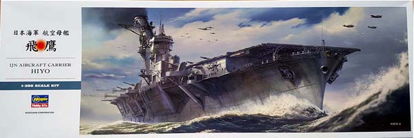
| Hasegawa 1/350 IJN Hiyo Class Aircraft Carrier Hiyo 1942 - Limited Edition kit |
| Background | ||||||||||||||||||||||||||||
| Japan had been a signatory of the Washington Naval Treaty
of 1922, which, among other things, limited Japanese aircraft carrier tonnage
to 60% of that of the United States and Great Britain. She did so despite
a great deal of internal dissension, trying to reconcile the conflicting
demands of maintaining parity with the other two powers with a preferred
ratio of 70% while faced with the fact that Japan could not successfully
compete in an unfettered arms race given her comparatively small industrial
base.
Though she had subsequently re-affirmed the limited ratios with the
1930 London Naval Agreement, Japan had signaled by the end of 1934 that
she would opt out of the treaty come its expiration in 1936. By the time
the treaty expired, Japan had already ramped up its warship building program
to its maximum capacity. In order to expand her carrier tonnage without
overtly alarming the other signatories, and to overcome her limited naval
shipbuilding capacity, Japan turned to a shadow building program, part
of which utilized commercial shipyards and designs that could be quickly
converted to auxiliary aircraft carriers.
|
||||||||||||||||||||||||||||
| Design | ||||||||||||||||||||||||||||
| Anticipating the need for more Trans Pacific passenger
capacity with the arrival of the 1940 Tokyo Olympic Games, and wishing
to showcase Japans maritime power, a pair of high speed, luxury ocean
liners were planned by Nippon Yusen (the NYK line) in 1937. These
ships would join other NYK luxury liners already in service such as the
Asama and Nitta Maru classes as Olympic Boats. The new ships were expected
to eventually dominate the Trans-Pacific passenger service lines.
The decision to build the new sisters was undoubtedly made easier by the internal knowledge that the Imperial Japanese Navy would help financially subsidize their construction. The Navy would do so in return for a design that allowed for a relatively quick conversion to an aircraft carrier, as well as the condition that the Navy could requisition the ship for such a purpose should wartime conditions make it necessary. This was not the first time this arrangement had been utilized. The three Asama Maru class ships had been built under the same set of conditions. Unfortunately, those ships had been unable to meet the ever evolving naval requirements of size and speed for an aircraft carrier, so they were never requisitioned for conversion. The three following Nitta Maru class ships were also constructed with subsidies and conditions. While they were ultimately converted to the Taiyo class carriers, their own design limitations meant that they werent really capable of anything more than ferry missions. So, there was a pressing need for more capable designs. Accordingly, the Japanese National Diet of 1938 gave budgetary authorization of a 60% building subsidy for the two new ships, Izumo Maru and Kashiwara Maru. The design phase was contentious. Naval requirements dictated a hull of large size and speed, with power to match. NYK concerns were mainly driven by the need to operate economically and to keep the overall budget affordable, even if largely subsidized by the Navy. The power plant was the major point of friction. Up to that time, most Japanese passenger liners, even large ones, had been powered by more economical diesel engines. However, the earlier classes had not been able to generate the speed or acceleration required by aircraft carriers. So, the Navy insisted on steam turbines. A byproduct of the choice of propulsion was ship size: a diesel engine arrangement did not require a hull quite as large as a steam turbine design. Neither design factor was favored by NYK. Ultimately, steam turbines were agreed upon, along with a two propeller shaft design. A six steam boiler configuration was chosen, with Izumo Maru utilizing Kawasaki-Lamont type boilers and Kashiwara Maru utilizing Mitsubishi type boilers. Not commonly recognized is the fact that both sets of boilers operated at 40kg/420*C, which were extremely high pressures and temperatures for an IJN ship. Even the new, high speed destroyer Shimakazes engines only operated at 40kg/400*C. The steam drove two sets of geared turbines, producing a total of 56,250 SHP to drive the propeller shafts. Also not generally recognized is that the turbines were not repurposed destroyer turbines, but specially designed for these ships. However, the entire the power plant was a compromise between merchant and naval service requirements; as such, it weighed considerably more than a comparable naval power plant. Each shaft drove a large, four bladed propeller operating at lower RPMs than typical for an aircraft carrier. This was a departure from the usual three bladed configuration of the time, and both factors were meant to maximize fuel efficiency. The propellers were also the largest ever installed on what would become an Imperial Navy ship, measuring 18ft./5.5m across. To accommodate a conversion to an aircraft carrier, various features were incorporated into the design, including a double bottom , additional fuel oil capacity, aviation gasoline storage tanks forward and aft of the machinery spaces, the installation of a longitudinal bulkhead to separate the turbine rooms, a strengthened main deck, more height between decks, a rearrangement of the superstructure and internal arrangements to ease the installation of aircraft elevators and hangars, more space for additional wiring, and a bulbous bow. Given their merchant origins, it was not possible to add much armor. Two layers of Ducol steel, each 25 mm (0.98 in) thick, protected the sides of the ships' machinery spaces. Their aviation gasoline tanks and magazines were protected by one layer of Ducol steel. In addition, the machinery spaces were further subdivided by transverse and longitudinal bulkheads to limit any flooding. The most unique feature was their bridge and funnel arrangements. Up to this point, the common practice for the Japanese had been to construct a small island structure along with separate funnels that exited the hull just below the flight deck on the starboard side and pointed down towards the water. However, there was a recognized need to further minimize the effect of exhaust gases on air operations, not to mention the effects of an extreme starboard side list on funnel openings close to the waterline. Experiments with a mock-up of Taihos bridge, then also under design at that time, presented a very favorable solution. The design integrated both bridge and funnel, similar to carriers of other nations. The funnel gases were vented upwards as with a typical funnel, only the top of the funnel was canted at a 26* angle outward to starboard, to direct the exhaust even further from the flight deck. Plus, there was the added benefit of enlarged bridge accommodations for the ships command. The design was implemented successfully. The new ships were planned to displace 27,000 tons, and to run at speeds in excess of 24 knots. Final specs were a standard displacement of 26,979 tons and a full load displacement of 29,471 tons, an overall length of approximately 719ft/ 219m , and a top speed of 25.5 knots. The flight deck was sizable. Limitations on top weight meant that the lower hangar of a two storey hangar design was shorter in height than typical for a Japanese carrier. This apparently limited the aircraft placed there to fighters only. The size of the air group suffered and was smaller than comparably sized carriers such as Hiryu or the Unryus. The air group was set at 48 aircraft with 5 spares. |
||||||||||||||||||||||||||||
| History | ||||||||||||||||||||||||||||
| Hiyo ( Izumo Maru was launched on June 24, 1941, and commissioned as Hiyo on July 31, 1942. Initially expected to be designated as an auxiliary aircraft carrier, the disastrous loss of four fleet type carriers during the previous month at Midway led to a reassessment of her designation by the IJN. Hiyo and her sister Junyo were both declared regular fleet carriers and renamed as warships. They became the second division element of the IJNs carrier strike force known as the First Air Fleet, along with the first division ships Shokaku and Zuikaku. Hiyo was subsequently designated flagship of CarDiv 2 under Rear Admiral Kakuji Kakuta. Hiyo spent two months working up in the Inland Sea, and subsequently joined Junyo at Truk in early October as part of the Combined Fleets effort to dislodge American Forces at Guadalcanal. In the preliminary actions of the Battle of Santa Cruz, CarDiv 2 sortied from Truk in the company of the Advance Force. It was intended that the air groups would provide air cover over Guadalcanal during efforts to retake Henderson Field. Initially, Division 2s aircraft conducted scouting and anti-submarine patrols. Then, on October, 17, CarDiv 2 launched its first combat air sortie, a combined airstrike of 36 aircraft (18 B5N2s carrying 800kg bombs and 18 A6M2s for escort, split evenly between Hiyo and Junyo) to attack American transports off Lunga Point on Guadalcanal. The airstrike turned disastrous. A vigorous defense by two USN destroyers and the Cactus Air Force on Guadalcanal led to the loss of over half the bombers for minimal American losses and minimal damage, if any, to shipping. Four days later, with CarDiv 2 and the Advance Force still operating to the north of Guadalcanal, Hiyo suffered another misfortune. In the late afternoon, a fire broke out in her starboard generator room. The fire was extinguished after 90 minutes, but her condenser was damaged. Hiyo was unable to make more than 16 knots, insufficient speed for battle conditions. Admiral Kakuta transferred his command to Junyo, along with 3 A6M2s, 1 D3A1 and 5 B5N2s from Hiyo to replenish Junyos air group. The rest of Hiyos air group transferred to Rabaul, to participate in the battle from that land base. Hiyo then retired to Truk on her port engine for temporary repairs. Ultimately, she returned to Kure, Japan in December for permanent repair. (Editorial note: In hindsight, Hiyos premature retirement from battle was a fortuitous turn of events for the Americans. After airstrikes from CarDiv 1 left Hornet dead in the water and Enterprise damaged, Junyo launched her own airstrike on USS Enterprise, then the sole operating US carrier. The attack did not damage Enterprise any further. Loss of the Hiyo air group had meant an attack by an unbalanced airstrike of smaller mass. A larger strike force would most likely have more effectively endured CAP attacks and further incapacitated Enterprise, or worse. The Japanese would then have been in a position to capitalize on the Americans lack of mobile air power, prolonging the fight over Guadalcanal with ever spiraling losses on both sides. ) Hiyo exited drydock at the end of December, 1942 upon the completion of her repairs. She spent time training on the Inland Sea, and re-entered at Kure at the end of February for additional AA, improved AA directors, and an additional Type 21 radar emplaced on the port, aft end of her flight deck, on a retractable mount. Its worth noting that her air group had continued to support operations around Guadalcanal from Rabaul until late December, when it rejoined the ship in Japan. Hiyo rejoined Junyo and CarDiv2 at Truk in March, 1943. The next two months were spent in operations to support the reinforcement of Rabaul (Operation I-Go) and the evacuation of the Aleutians. Hiyo returned to Japan in June. Outside Yokosuka harbor on June 10th, Hiyo was torpedoed by USS Trigger. Two hits on the starboard side caused severe flooding and loss of power, but Hiyo eventually made it back to Yokosuka under her own power. Repairs were completed in mid September. Her AA suite was further bolstered with additional single and triple 25mm mounts. Her air group, along with that of light carrier Ryuho, was sent on to Singapore for extended training at the beginning of October. Hiyo and Ryuho eventually joined up with their respective air groups at Singapore by early December, 1943. Unfortunately, both air groups were then again divorced from the carriers to fight at Rabaul, where they incurred 50% losses. In the meantime, Hiyo spent the next month on aircraft ferry duty between several South Pacific locations, arriving back at Kure at the beginning of January, 1944. She remained in the Kure area for another four months while continuing to train yet another reconstituted air group. In May, she departed with other units for forward staging at Tawi Tawi in the Phillipines. Hiyos demise came on June 20, 1944 during the Battle of the Philippine Sea. As part of CarDiv 2 (Junyo, Hiyo, Ryuho) with Admiral Ozawas Force B, she had already launched two strikes the previous day with minimal results and high losses. All of the Japanese forces were withdrawing to the west, expecting to regroup for new attacks the following day. Scouts from US Task Force 58 had searched fruitlessly all day for the Japanese. A mid- afternoon sighting prompted an all out late afternoon attack by the Americans. Learning of the approaching enemy aircraft, Hiyo turned into the wind to launch two B6N Tenzan smoke screen aircraft. However, doing so left her 6,000 meters behind Junyo and relatively exposed. Several bombs and at least one torpedo struck her during the ensuing attack. Hiyo took on a slight list, maneuvering on one engine. Eventually, she stopped dead in the water with a 9* list to starboard, though she was not then in imminent danger of sinking. Nagato was ordered to take her in tow. Unfortunately, gasoline vapors from cracked aviation gas storage tanks permeated the ship, and just after 1800 hrs, Hiyo was rocked by an enormous gasoline vapor explosion which doomed the ship. Burning fiercely and settling quickly by the stern, she sank a little more than an hour later. Approximately 250 men were lost, but over 1,400 of her crew were rescued by the escorting destroyers. |
||||||||||||||||||||||||||||
| The Kit | ||||||||||||||||||||||||||||
| This kit was released in July, 2017, as a companion to
Hasegawas 1/350 Junyo 1944 kit, released the previous November. As such,
the kits are largely identical, with most parts common to both kits. The
instructions identify which parts are not to be used with the Hiyo version.
Differences are primarily limited to the extent of the AA suite, the AA
direction finding equipment, flight deck markings, and type of aircraft.
This particular boxing is offered as a limited edition kit with special decals. Hasegawa states that the kit can be built as either Hiyo or Junyo during the Battle of Santa Cruz, October, 1942, and the very nice decal set has flight deck and air group markings for both ships. The air group is composed of early war aircraft. There are also several dedicated photo etched parts sets sold separately by Hasegawa. The kit is very sharply molded in gray styrene plastic with a clean finish and no soft edges or details. There were a few subtle sinkholes on the far ends of the flight deck, but its hard to say whether or not these possible sinkholes will actually be visible when painted. They just may be blemishes. There was no flash whatsoever on my sample. The sprue breakdown is as follows:
|
||||||||||||||||||||||||||||
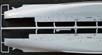
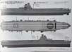
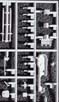
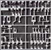
| Sprue A - Hull | ||||||||||||||||||||||||||||
|
The kit hull is split longitudinally into two halves, each connected to the same, very large sprue along its length, with runner extensions for each bow and stern portion. The sprue extensions are set into cutouts in a heavy cardboard tray that fits full length and width into the kit box. Doing so keeps the hull halves from shifting during transit. Its smart packaging, and a set-up common to many of Hasegawas 1/350 ship kits. |
||||||||||||||||||||||||||||
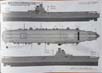
|
The hull is beautifully rendered, with wonderfully sharp detailing. Its also full hull. The hull sides are thick at 2mm, and the styrene is on the hard side, which has allowed for a high degree of fidelity for all the molded details. Virtually everything is there: bilge keels, anchor recesses, hawseholes, portholes (some of which are sealed with covers), porthole eyebrows, grab rails, a degaussing cable with brackets, several prominent air intakes along the hull, a large, starboard side sponson that helped support the island, smaller sponsons with support brackets, hull plating, some hatches and small air intakes, a number of small equipment boxes, and assorted small piping. Its truly a great looking hull. The hull interior has multiple mounting points for the heavy duty internal styrene bracing that helps connect the hull halves together in a rigid stance. Nitpicks are few. The biggest may be the sealed portholes with their covers. Clearly, Hasegawa carried over its Junyo 1944 kit hull to use here. This is completely understandable from a production cost perspective, but incorrect for a 1942 version of either sister. At that point in time, the lower deck portholes were not yet being sealed off in IJN ships to improve watertight integrity. That trend did not begin until late 1943 into 1944 for most ships. So, to be historically accurate, the covers have to be removed and the portholes drilled out. Thats not impossible to do, just tedious, as there are a great many sealed portholes. Of course, all the unsealed portholes have eyebrows, so any modeler going down this road either has to scrape off all the eyebrows (which is arguably okay for this scale) or replace them on the formerly sealed portholes. That said, it seems unlikely that leaving the porthole situation as is will detract from the finished model for most folks. Also debatable are the finely recessed hull plating seam lines. The kit plating scheme consists of individual plates, which suggests that Hasegawa has taken advantage of the extensive archival reference material on Junyo to fully portray the kits plating pattern. What makes it debatable is that the hull seams wouldnt have been recessed. The plates abutted each other in any given horizontal strake, and the strakes alternated over and under each other on the vertical axis. Nor is it likely that individual plates should really be visible in this scale. However, the trend in kit production nowadays is to present ever greater amounts detail (driven in part by the greater use of slide mold technology, and by digital photography), so prominent plating seams it is. Dont get me wrong; it looks good, just overscale to my eyes. Again, I imagine most folks will be quite happy with it as is. Interestingly, one of the hull seams is a very subtle, raised line all around the hull, denoting the waterline. Its a helpful touch for painting the hull. It can also act as a guide for cutting the hull down to a waterline stance. Lastly, one could also opt for replacing the finely molded handrails that line much of the hull with PE versions. (Hasegawa, among others, has a dedicated PE fret for these in 1/350.) Personally, I think the molded versions so nicely done, and so close to scale, that Im not sure it would be worth the effort to replace them.
|
||||||||||||||||||||||||||||
*because the hull is split in half, this measurement is only an estimate.
The actual width could easily be close to 76mm.
|
||||||||||||||||||||||||||||
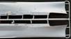
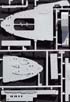
| Sprue B Planked portions of the flight deck | ||||||||||||||||||||||||||||
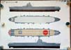
| The planked portion of the flight deck is molded in two
large, adjoining sections. So, yes, that means there is a seam across
the width of what should be an unbroken expanse of flight deck. Hasegawas
own marketing shots make it hard to see any seam, but in the age of Photoshop,
its hard to say how realistic this is.
(There is precedent for the multi-piece flight deck with Hasegawas 1/350 Akagi kit, but that kits flight deck is split along some expansion joint lines. The Hiyo class ships did not feature expansion joints built into the flight deck as did most of the purpose-built IJN carriers. The main deck was constructed as the strength deck, so that no expansion joints for the flight deck were required.) Hasegawa has engineered a connecting piece (R7) meant to join them tightly
together by cementing this connector to the undersides of both flight deck
sections. The adjoining ends are sharply squared off, and the planking
lines do line up, so one can hope that a good, tight fit that minimizes
any seam is possible.
By the way, this seam is somewhat mitigated in the 1944 version of Junyo. Hasegawa has gotten around this hurdle by replicating what was a full flight deck width, alternating red and white, warning strip decal and placing it on one side of the seam, thereby disguising it. It seems to work pretty well too, judging by Hasegawas beauty shots for that version. Presumably, a 1944 Hiyo would likely have the same type of marking. Setting aside this unexpected hurdle, the rest of the flight deck is wonderful executed. Planking width is identical that of the Akagi kit at 0.03 inches, which equates to a 1/350 scale width of 10.5 inches. This is still just a little overscale, but fully 25% better than Fujimis standard .04 inch planking width in 1/350 scale. The planks are separated by a very thin recessed seam, also finer than those seen on Fujimi flight decks. Detailing on the flight deck includes a large recessed box in the forward flight deck with structural cross-members that supported the wind barrier in front of elevator #1, subtle depressions for the tie-down holes, embossed small boxes denoting deck strip lighting for night-time operations, recessed outlines for the paired bases of each arresting wire (nine in total), more (properly) recessed channels for the wire cabled cross-deck crash barriers and the anchoring struts used to raise and lower them, and two kinds of small platform extensions along the deck edge; one for large illumination lights used for night-time deck operations; the other for smaller lights denoting the flight deck perimeter. There are also large apertures for the two elevators. The only other nitpick has to do with the deck edge rain gutters, or rather, the lack of them. While the sisters did not have a sizable band of treaded metal around the edge of the entire flight deck as did the purpose-built carriers, they did have rain gutters all around as did the other ships. Hasegawa has opted to just show a thin, flat, deck edge plate all along the planked sections of the flight deck, with another thin seam separating it from the planking. This same thin band continues outside the treaded portion of plating for the bow and stern pieces of the flight deck on Sprue D. Now, just for the record, there happens to be a documented moment in May, 1944 when Junyo was photographed with perforated covers closed over the rain gutters. This occurrence took place while she undergoing inclination tests at Kure. In all other instances, her gutters were photographed open and uncovered. I cant say whether or not this was a unique circumstance, but I certainly cant recall ever having seen such covers over the rain gutters on any other IJN carrier in any other instance. So, it is possible that Hasegawa has chosen to use this particular representation for its flight deck, and specifically left the molded gutters off. I tend to doubt that as an explanation, but it can be argued as such. In any case, the gutters can be scratch-built, though care must be taken to carefully remove and re-attach the small lighting platforms. Dimensionally, the flight deck is quite accurate. The length measurement includes the entire molded flight deck and the metal plated bow and stern portions found on Sprue D. Actual versus scale and kit dimensions: |
.jpg) |
|||||||||||||||||||||||||||
 |
||||||||||||||||||||||||||||
|
||||||||||||||||||||||||||||
| Sprue C | ||||||||||||||||||||||||||||
| A small sprue thats attached by extension to Sprue B, this one holds the left and right housings of the propeller shafts, the two propeller shaft brackets, and the rudder. Smartly, the exposed portion of the propeller shaft that emerges from the housing to extend through the bracket is molded in full with its radii complete, so there is no awkward matching of two shaft halves. The rudder is detailed with the engraved lines to denote weld seams. | 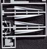 |
|||||||||||||||||||||||||||
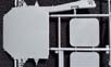
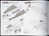
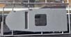
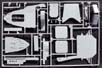
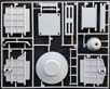
| Sprue D | ||||||||||||||||||||||||||||
| This is another large sprue with the metal plated bow and stern portions
of the flight deck, the two aircraft elevators, the forecastle deck, the
stern boat deck, a recessed boat storage compartment, two sections of the
aft hangar deck bulwark with a louvered hangar service door, a catwalk
and a small platform for those sections, both halves of the lower portion
of the bridge island, both halves of the funnel, and a molded insert with
exposed interior dividers on one side that also acts as an interior brace
for the bridges halves. The port side of the bridge has very large, exposed
apertures, through which the interior piece can be seen.
Everything is sharply molded, and there are a lot of small details, particularly all manner of air intakes and housings, mooring bits, anchor chaffing plates, and the like. The flight deck portions have treaded metal edges, as do the forecastle and stern decks. All the metal surfaces have plating seams. The flight deck portions and elevators have tie-down depressions as does the planked flight deck. One point of differentiation between the two sisters was the shape of the front corners of the bow section of the flight deck. Junyos was sharply angled, while Hiyos had small curves. As this kit utilizes the Junyo version, the curves are not present. With some care, the ends could be rounded off, but some care must be taken, and a little work done to restore the strip that is meant to represent the rain gutter. Its a very small detail, and probably not worth the effort. This same bow section of the flight deck in my kit had some very slight, barely visible sinkholes on the flight deck surface. Im not certain that these would be apparent at all after painting. |
 |
|||||||||||||||||||||||||||
|
||||||||||||||||||||||||||||
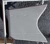
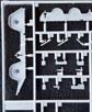
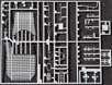
| Sprue E | ||||||||||||||||||||||||||||
| Contains the extensive, interlaced girder support structures that underlie
the bow and stern sections of the flight deck that are elevated above the
forecastle and stern, the components of the mainmast, the large strut supports
that held up the elevated sections of flight deck (with molded on drain
pipes for runoff from the rain gutters), auxiliary piping for the funnel,
the funnel grill and retainer band, some winches, some small equipment
pieces, and the jackstaffs for the bow and stern.
The instructions also show the installation of an externally mounted emergency rudder. However, this is almost certainly an erroneous carryover from the 1944 Junyo kit. The addition of such equipment did not occur until later in the war, usually sometime in 1944. On another note, know that Hasegawa offers a separate PE set with metal girders to replace the plastic versions on this sprue, referred to as the Super Set for Junyo, #QG65. |
 |
|||||||||||||||||||||||||||
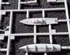
| Sprue F | ||||||||||||||||||||||||||||
| Attached to Sprue E, this is a small sprue that contains the two four-bladed propellers for the ship. Aficionados will be pleased to note that the blades are canted in opposite directions for each prop. | 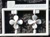 |
|||||||||||||||||||||||||||
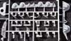
| Sprue G | ||||||||||||||||||||||||||||
| This is a sizable sprue with a lot of small parts.
Among the more prominent ones are the upper two levels of the bridge, the
AA Command Deck the topmost deck, and the Compass Bridge Deck under it,
along with a number of smaller bulwarks for either end of the bridge, several
smaller bridge platforms and deck insets, the baffle inside the funnel,
multiple support girders for the funnel, the foremast and legs, the Type
21 radar that sits atop the bridge, two small motor launches, a fair number
of ancillary small platforms and equipment pieces, and the components of
the large aircraft handling crane.
Everything is crisply molded with nice detail. The AA command deck is particularly so, with braces on the inner side of the bulwark, treading on the deck and a baffled windscreen on its leading edge. While the baffles on the windscreen are of one solid piece, the depressions are deep enough to accept a dark wash with good effect. Not every part on the sprue is used. Some are applicable to only the 44 version. For example, part G81, which is a small deck on the 01 level at the front of the island, is used instead of G82. The difference is that G81 has a molded base for the earlier (circa 1942) Type 91 HA director, whereas a different director set-up for late war eliminates the need for a separate base. |
 |
|||||||||||||||||||||||||||
 |
||||||||||||||||||||||||||||
| Sprue J | ||||||||||||||||||||||||||||
| This is a larger sprue that is primarily composed of the sponsons and platforms that ring the both the flight deck and hull, and support the numerous 12.7cm and 25mm AA mounts. All platforms have treading, support trusses, and inner bulwark braces. Many of the smaller platforms have molded on seating benches, with wooden slats. Many of the larger, individual struts that support the platforms off the hull are included as well. | 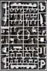 |
|||||||||||||||||||||||||||
|
||||||||||||||||||||||||||||
| Sprue L | ||||||||||||||||||||||||||||
| Another small sprue, this one carries the leading bulkhead for the upper hangar deck, two platforms meant for either side of the forward hangar enclosure, some other small platforms placed under the forward and aft ends of the flight deck, the support structure that underlies the numbers one and two 12.7cm HA mounts foremost to port and starboard, and some stern mooring bits. | 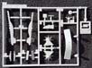 |
|||||||||||||||||||||||||||
| Sprue N | ||||||||||||||||||||||||||||
| This is a very small sprue holding clear plastic parts the compass bridge deck windows, and the lenses for the four 110cm searchlights. |  |
|||||||||||||||||||||||||||
| Sprue Q x 4 | ||||||||||||||||||||||||||||
| Here are included several components for a twin 12.7cm40 cal. High
Angle AA mount including barrels, recoil tubes, mounting base rings, and
the support strut that juts out of the hull mounted sponson to hold up
the entire mounting structure. Theres also a lot of small equipment pieces
for the forecastle and aft boat deck as well as hangar bulkheads, including
flight deck main support struts, anchor capstans, several types of mooring
bits, some small support stanchions and cross-members, several types of
mushroom air vents, 12cm binoculars, 30cm and 60 cm searchlights, 2kw daytime
running lights, paravanes, deck winches, flight deck covers for the retractable
110cm searchlight housings, main aerial masts, landing light arrays, small
boat davits, small ladders, a 4.5m rangefinder telescopic tube, and an
RDF antenna (molded with open rings!) , among others.
Several other parts are not meant to be used with the 1942 version, including a really nice Type 94 High Angle gun director. Good for the spare box. |
 |
|||||||||||||||||||||||||||
| Sprue R x 2 | ||||||||||||||||||||||||||||
| This sprue is devoted mostly to the interior braces that make the hull
rigid by connecting the two hull halves at various points. The braces are
much like big bulkheads. Theres a couple of smaller, strut like braces
as well. Also included are two flat plates that attach to the underside
of the flight deck and cover the elevator apertures. These provide a recessed
surface upon which to rest the elevator plate itself.
Unfortunately, there are no components for an elevator well of any sort here, or elsewhere in the kit. Thats unfortunate, as elevators of this sort are unique to a carrier, and provide a nice opportunity to show off additional detail. Its a curious omission, as a simplistic one storey well could easily be fitted within the confines of the hangar spaces, much as does the Akagi kit. I believe a more correct two storey version could be fitted as well, though both would have limitations on the amount of hangar deck and spaces that could be displayed. (So, here is a nice opportunity for someone to provide aftermarket elevator wells. I could certainly visualize 3D printed versions.) The aforementioned part R7 that joins the two planked portion of flight deck together is also here, as are two pedestals and bases for mounting the full hull for display. |
 |
|||||||||||||||||||||||||||
| Sprue S | ||||||||||||||||||||||||||||
| A one piece sprue, this is one of the large blackboards that were used to display last minute instructions and data to the flight crews before manning their aircraft. Its mounted on the portside of the bridge island just above the flight deck level. Another one is already molded onto the side of the island. Why Hasegawa chose to mold one of them separately is beyond me. Both get filled with black decals proved for on the decal sheet. Or, they could be filled with paint. | 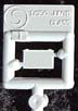 |
|||||||||||||||||||||||||||
| Sprue UB | ||||||||||||||||||||||||||||
| This is a black, small link chain meant to be used for the anchor chains. You get approximately 100mm/4 inches of chain. It runs around 25 links to the inch. It is the same sort of chain that comes with the Akagi kit, among others. It appears correctly scaled, but I dont know for sure. | 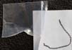 |
|||||||||||||||||||||||||||
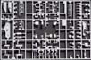
| Sprue AE x 2 | ||||||||||||||||||||||||||||
| This is primarily a small ships boat sprue. If it looks familiar, thats because it is, in fact, the same sprue as is sold separately as Japanese Navy Warships Boats Set A (H), but without the small PE fret that comes with that set. Not everything on this sprue is used for this kit. Those items which are applicable are: components of a 12m motor launch, an 8m launch, a 9m cutter, a 6m sampan, and the ships anchors. Also included are parts for a 12.7cm AA practice loading mount. Everything else is for the | 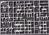 |
|||||||||||||||||||||||||||
 |
||||||||||||||||||||||||||||
| Sprue AF x 2 | ||||||||||||||||||||||||||||
| Like the AE sprue, this ones also sold separately. Its listed as Japanese Naval Vessels Equipment St A (Machine Gun and Optical Weapons) (H), but again without the small PE fret that comes with that set. Like-wise, not everything is used for the Hiyo kit. Important are: flight deck illumination lights, all the components for both the triple 25mm AA mounts, and the other twin 12.7cm40cal. High Angle AA mounts, 25mm AA directors, housings for the 110cm searchlights, searchlight controllers, the shielded portions of the Type 91 HA mount directors, and some additional 12cm lookout binoculars. | 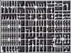 |
|||||||||||||||||||||||||||
| Sprue AG x 2 | ||||||||||||||||||||||||||||
| This is yet another ships boats sprue, and again, only some of the parts are utilized. These include the components for a 13m daihatsu, a 12m motor boat and the chrysanthemum shield worn at the bow. | 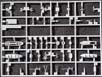 |
|||||||||||||||||||||||||||
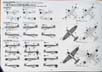
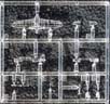
| Sprue AI x 3 | ||||||||||||||||||||||||||||
| These are the aircraft sprues, molded in clear plastic. All are early war models, as befits a 1942 version. These sprues are identical to the ones in the Akagi kit, and also sold separately as 1/350 Japanese Navy Carrier-Based Aircraft HSGS2130. Each sprue holds one Mitsubishi A6M2 Type O Model 21 Zero fighter, one Aichi D3A1 Type 99 Model 11 Val dive bomber, and two Nakajima B5N2 Type 97 Model 3 Kate torpedo bomber. In addition to fuselage, wing, stabilizer, propeller, and landing gear parts, there are drop tanks for the Zeros, 250kg bombs for the Vals, and a choice of either a Type 91 aerial torpedo or an 800kg bomb for the Kates. | 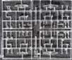 |
|||||||||||||||||||||||||||
 |
||||||||||||||||||||||||||||
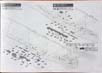
| Decal Options: | ||||||||||||||||||||||||||||
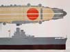
| This is a very large sheet, to accommodate the flight deck lines, markings, air group markings, miscellaneous items, and flags for both ships in the latter half of 1942. The decal sheet is clearly printed with no registration issues. Oddly, there are a handful of the smaller decals that are not to be used for either vessel. I cant imagine why these were included, as the sheet was created specifically for these ships in this timeframe. | -1-350-Hiyo-Junyo-42-decal-sheet.jpg) |
|||||||||||||||||||||||||||
| Flag Sheet | ||||||||||||||||||||||||||||
| In addition to the decal based flags, there is another sheet containing a variety of 1/350 Japanese naval ensigns, admirals flags, and various signal flags. Its printed on paper with adhesive backing. | 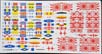 |
|||||||||||||||||||||||||||
| Instructions | ||||||||||||||||||||||||||||
| The kit comes with a 32 page booklet printed in black and white. Its clearly illustrated, thorough, and mostly in Japanese. Assembly is shown step-by-step via exploded, three point perspective illustrations. Sub-assemblies are shown in good detail, and the construction process appears straightforward. | 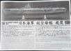 |
|||||||||||||||||||||||||||
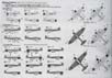
Four pages are devoted to the specific aircraft and flight deck markings
for both Hiyo (August, 1942) and Junyo (October, 1942). Aircraft
decals are provided for six Zeros, six Vals, and twelve Kates for each
ship, which makes for a nice strike package, depending on which attack
aircraft are used. (Keep in mind that individual Japanese carriers rarely
launched a strike composed of both Vals and Kates. Typically, given a two
carrier division, each ship would contribute one type of strike aircraft,
plus escorts. Even when operating alone, a carrier almost always launched
one type of attack aircraft. A mix of ASW aircraft aloft was the typical
exception.)
|
||||||||||||||||||||||||||||
| Painting and Rigging Sheet | ||||||||||||||||||||||||||||
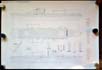
Also included is a color print of the ship in 1/350 scale,
rolled into a tube within a clear plastic sleeve. One side has a painting
guide keyed to the GSI Creos and Mr. Color paint lines. The other side
is another 1/350 diagram highlighting the ships rigging. This schematic
is a feature not typically include with either 1/700 or 1/350 Japanese
aircraft carrier kits, and is quite welcome.
|
||||||||||||||||||||||||||||
| Final Thoughts | |
 This
is a superb kit, at least in the box. The research and engineering behind
it are self evident. It fired my imagination while examining it and made
me want to start construction immediately. I imagine that fit will be very
good, as typical for the Hasegawa 1/350 kits. This
is a superb kit, at least in the box. The research and engineering behind
it are self evident. It fired my imagination while examining it and made
me want to start construction immediately. I imagine that fit will be very
good, as typical for the Hasegawa 1/350 kits.
A nice plus is the option to build either CarDiv 2 sister in the fall of 1942 as the campaign for Guadalcanal reached its peak. The more determined modeler can now build both ships in the same time frame, along with some of the escorts, all in 1/350. Who ever imagined that such a scenario would ever be possible? Thanks to Hobbico Model Distributors for the review sample. They are your US distributors for Hasegawa. Suggested US MSRP appears to be $349.99, though many discounts are available, particularly at this time of year. |
|
| This is an in-box review showing the kit contents. We welcome your input and comments in the review section of the forum especially if you can share details about fit, ease of assembly and accuracy. Click the logo on the right to join in the discussion. |  |