|
By Felix R. Bustelo
Part II: Historical Background Part III: The Kit and The References Part IV: Hull Modifications Part V: Deck Preparation Part VII: Superstructure Enhancements Part VII: Armament Part VIII: Other Details Part IX: Painting The Camouflage Scheme Part X: Let's Make Waves Part XI: Conclusion Part I: Introduction This article will document my build of the Airfix
kit of the HMS Ajax and what I needed to do to convert her into her
mid-1941 fit, when she served in the Mediterranean based out of Alexandria.
I made a couple of mistakes (and I am not ashamed to admit it!) but they
did not adversely impact the model; these will be noted in this article.
I may inadvertently omit some things I did, but I have tried my best to
remember as much as I could. To build and detail this model, I used the
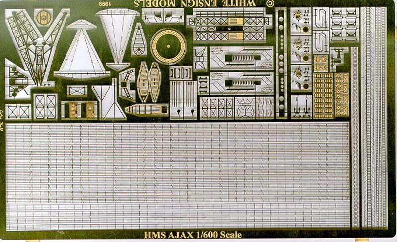
fine 1/600 scale Ajax photoetch set from White Ensign Models. I will not
go into specifics on the application of this set, as this is covered adequately
by the instructions provided by WEM.
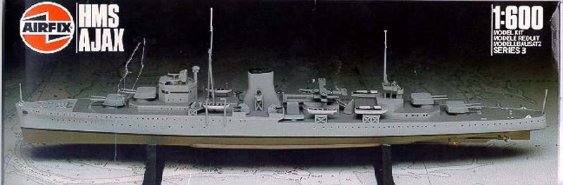
Part II: Historical Background The Ajax was one of five Leander Class light cruisers built during the 1930s. The design of this class was a result of the London Conference of 1930, which allowed Great Britain to build an additional 91,000 tons of cruisers up to the end of 1936. The Leander class was to account for a portion of this tonnage allowance. Four of the five Leanders were built for the Royal Navy (Leander, Ajax, Orion, and Neptune) and the fifth was built for New Zealand (Achillies). An additional three "modified" Leanders were built for Australia (Hobart, Sydney, and Perth). The Leander class was armed with eight 6-inch guns in four twin turrets and eight 4-inch anti-aircraft guns in twin mountings. Due to improvements in design, the number of boilers were reduced in this class and the uptakes were trunked into a single, ducted funnel. This was a very distinguishing feature of the original five Leanders. The "modified" Leanders had a different internal arrangement and had twin funnels as a result. The HMS Ajax is best known for her participation in the Battle of the River Plate against the German pocket-battleship Graf Spee. In this engagement she was hit seven times, with one of the German raider's 11-inch shells disabling her "X" turret. The Ajax under went repairs from December 1939 through July 1940, after which she joined the 7th Cruiser Squadron in the Mediterranean. Her career in this theater was very active; she successfully engaged an Italian torpedo-boat force, sinking two; participated in raids in the Straits of Otranto; escorted Malta convoys; and fought in the Battle of Cape Matapan. The Ajax was part of the evacuation force after the fall of Greece and attacked enemy convoys during the Axis invasion of Crete. She sustained further damage in several incidents and she finally had to be removed from service for major repairs at the New York Navy Yard from March through October 1943. She then returned briefly to the Mediterranean but was recalled to England to serve in Operation Overlord (the invasion of Normandy), sailing off Gold Beach. Afterwards, she returned to the Mediterranean to support the invasion of southern France and later the reoccupation of Athens. The Ajax saw little service after the war and she eventually went to the breakers on November 18, 1949. Part III: The Kit and The References The 1/600 scale Airfix kit is the only plastic injection-molded
kit of the Ajax and can be the basis for modeling any ship in the Leander
class of light cruisers. However, this kit is one of the older Airfix offerings,
first appearing in 1965, and is very sparse in detail. My kit was an older
release and the box art has a photo of the model built out of the box.
As you can see from the scan of the cover, the kit is very basic but an
adequate starting point. Also, the kit best represents the Ajax as she
appeared in 1939, at the Battle of the River Plate against the Graf Spee,
so some changes had to be made to build her circa 1941.
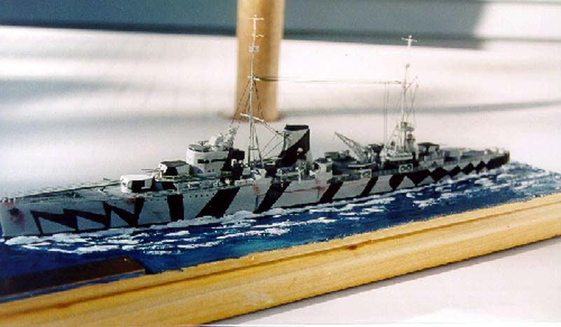
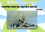
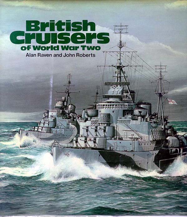
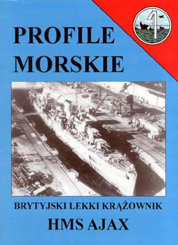
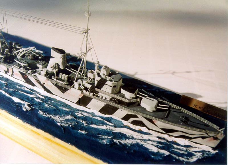
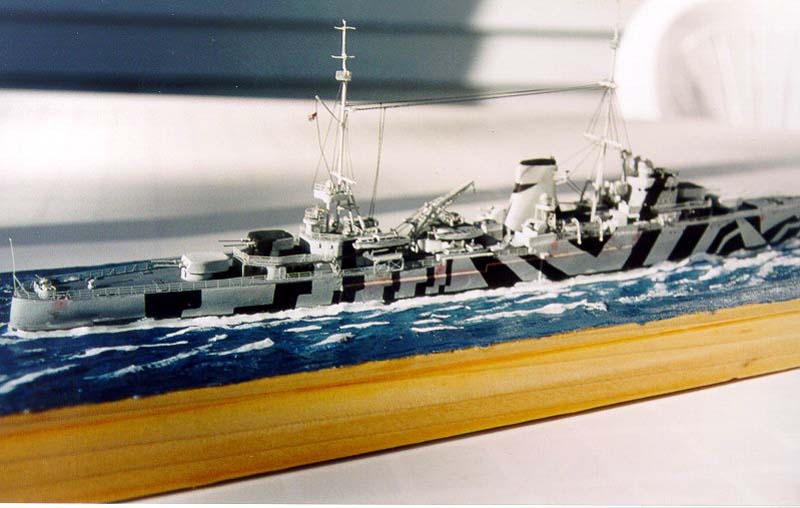
There were several reasons why I chose the Ajax from the numerous kits in my closet as my next project. First off, I always liked this class and this ship in particular and I had a desire to build her. Next came the release of the excellent photoetch set from White Ensign Models for this kit, which spurred my interest further. I had good references in my possession, so I was able to overcome a hurdle faced by many of us. However, what really made me want to tackle this model was the dazzle camouflage pattern I saw in Alan Raven's Camouflage Volume One: Royal Navy 1939-1941; I just had to build her wearing this wild scheme. My first reference was the Profile Morskie volume of the HMS Ajax (referred to as PM from here on). This was the first Profile Morskie I had seen and I was quite surprised by the numerous detail drawings included in this book. There has been some debate about the accuracy of the content of this series of books, but I felt that it provided me with the visual information I needed to detail my model. The artwork for this book is based on (some say plagiarized from) the extensive British Cruisers of World War II by Alan Raven and John Roberts. This book is considered by many as the definitive reference on the topic. To be fair to the publishers of Profile Morskie, they do list this as one of the references used on the second page of this book. As to the degree of liberty that the publishers took with this artwork, I cannot say. During the early phase of my project I was fortunate enough to come across a used copy of the Raven and Roberts book Ajax (referred to as R&R from here on) at an extremely reasonable price. The plans provided in both the PM and the R&R books depict the Ajax as she appeared in 1941, which is slightly different from her appearance in 1939. Finally, as I had mentioned, for the camouflage scheme I had the WR Press publication Camouflage Volume One: Royal Navy 1939-1941 by Alan Raven (referred to as Camo Vol.1 from here on), which on page 42 had her wearing a dazzle scheme in mid 1941. So, I now had all of the pieces I needed to proceed with the project.
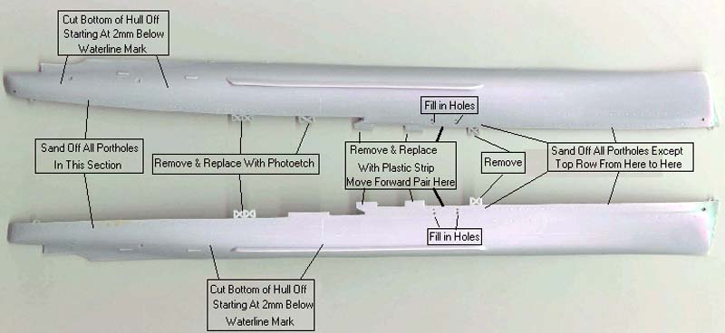
I planned to build a seascape with this kit, so I measured 2mm below the waterline and removed the bottom of the hull halves with a razor saw. Since the WEM photoetch set provides cruciform sponson supports, I carefully removed the plastic versions from the hull halves using a #11 Exacto blade. The locations of the forward twin four-inch secondary guns are in the incorrect spot for the 1941 fit. At some point, these guns were moved forward some more and the davits for the whalers were moved back between the mounts, basically swapping positions. The splinter shields in the kit are also incorrect as they should form roughly a "U" shape around the guns and not an "L" shape. Since I had to relocate the forward splinter shields, I decided to remove the kit versions and replace them with thinner 2mm-width strip styrene. Some of the splinter shields were molded into the hull halves and the others into the upper deck part, so I carefully removed them using a #11 Exacto blade. The three sides to the splinter shields were not identical in length. The side facing out along the edge of the deck was 9mm in length. The longer side was 7mm and the shorter side was 5mm. These measurements were based on my resizing of the PM plans to 1/600 scale. The locator holes for the kit's whaler davits were filled in with white Squadron putty and sanded smooth. According to the profiles in the R&R and PM books, most of the portholes appear to have been plated over in this fit. Since these are represented on the kit as faint raised circles, I sanded smooth the ones that needed to be removed. These included all of the ones aft, the entire bottom row forward and the ones on the top row just forward of the breakwater and aft of the bridge superstructure. The remaining portholes I opened up using either a #72 or #73 micro drill bit. The profiles in my references show that some plating was added to the sides of the hull approximately amidships. The kit has some faint raised lines showing this on the hull halves. The shape of this plating can be loosely described as the letter "L" resting on its back. I measured the outline on the kit's hull and transferred these measurements to some sheet styrene and cut out the shapes. After attaching the plating to the hull using plastic weld and smoothing out the edges using white glue as a filler, I realized that the dimensions of the outline on the kit's hull was slightly different when compared to the profiles. The narrower portion of the resting "L" was narrower in the plans than the what the kit represented. Photographs included in the references confirmed this. At this point it was too late to do anything about it and only two alternatives were available: buy a new kit and start over or proceed as is and adding this faux pas to my experience. I decided to follow the latter course of action. The lesson learned here: pay closer attention to your references! A test fit of the two hull halves showed that the locator pin
on one half did not properly line up with the corresponding hole of the
other half. The removed that pin, carefully lined up the hull halves and
applied plastic weld to the seam on the inside of the hull.
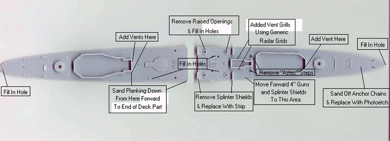
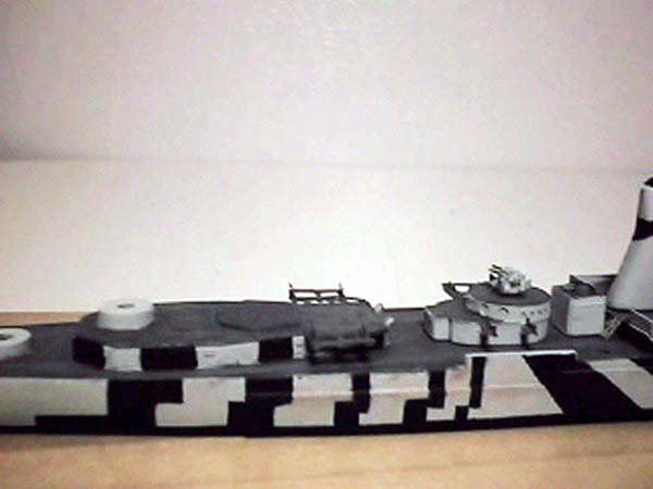
First thing I did was to sand off the molded in anchor chain and replace it with the chain from the photoetch set. The locator holes for one of the launches, the funnel searchlight platform supports and the ensign/jack staffs were not going to be used and needed to filled in. I glued pieces of styrene strip cover the holes from underneath the deck and filled in the holes the white Squadron putty. The searchlight platform supports and staffs were going to be replaced with the photoetch versions. I didn't bother to fill in the hole for the crane, as the photoetch base would cover it up. I also carefully removed the molded in "Aztec steps" inclined ladders with a chisel blade and eventually replaced them with photoetch versions. The kit's deck has 4 raised openings for the twin four-inch guns. According to my references, there is some raised flooring underneath these mounts within the area of the splinter shields. I also had to relocate the forward mounts, so I had to fill in the ones I no longer needed. Finally, I was going to substitute the kit's four-inch guns with resin WEM upgrades, so these little mounds had to go. I carefully removed them using a chisel blade being careful not to mar the surrounding deck area. The openings for the aft mounts I could leave as I was going to cover them with some styrene for the flooring, but the forward ones needed to be filled in and sanded smooth. The raised flooring was made from very thin sheet styrene and glued into place using plastic weld. The reference plans showed that the deck area around catapult and crane are steel and not wood, so I sanded the molded in planking smooth in this area. To detail the decks a bit, I added photoetch hatches to the decks, using the PM plans as a guide. Once I glued the two main deck parts into place, I reinforced
the joints using five-minute epoxy. I applied the epoxy using a plastic
coffee stirrer along the joints, which also helped fill in some of the
minor gaps between the deck edge and the hull. There were slight gaps at
the very peak of the fo'c'sle and the stern. I applied some white glue
and wiped it smooth with a damp cotton swab.
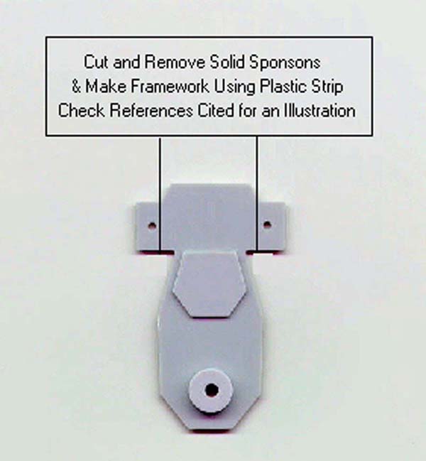
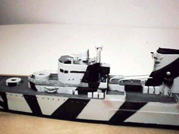
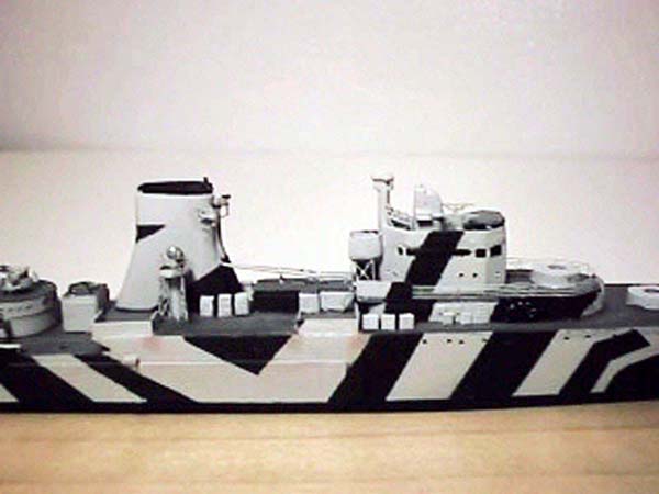
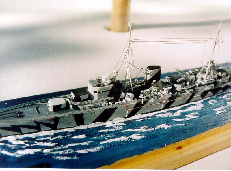
Part VI: Superstructure Enhancements The superstructure walls are molded directly into the decks, which makes painting a tad more tedious. These walls are also completely bare of any detail, which needs to be remedied. I added photoetch watertight doors using the PM plans as a location guide. I also made some portholes in the superstructure walls using a micro drill bit. Since the kit did not have any represented by the typical raised outline, I had to carefully drill mine again using my references as a location guide. According to the plans, at several points on the superstructure walls there were square plates covering openings. These plates were hinged so that, I assume, they could open out for ventilation and light. Since these were quite prominent, I decided to add them using 1mm wide by 0.3mm thick strip styrene cut into 1mm lengths to form squares. By my count I needed 26 but I made more anticipating losing a few along the way (which I did). I glued them into position using white glue, which would allow me to position them before the glue dried. If I used CA glue, I feared that the glue would set before I could correctly position the bit of plastic. As painstaking as this was, I was glad I did it as it added a nice level of detail to the kit. According to the plans, there are three rectangular vents located along the deckhouse walls. One is located in front of the forward deckhouse behind A turret slightly starboard of the centerline. The over two are located facing forward against the aft deckhouse, on either side of the crane. I used rectangular brass strip to make these vents. Since I needed to bend the tops over a bit to form an elbow, I figured that brass would be easier to bend into shape. I shaped the bits of brass, trimmed as needed and sanded the ends smooth using a file. I glued them into position using CA glue. Later on, after the superstructure was painted, I touched up the vent "openings" with a bit of Floquil Grimy Black paint. The photoetch set comes with vent grills that go on either side of kit part number 14. The plans show that the vent housings just forward of the funnel also have some grills, but these are not provided on the WEM set. To simulate vent grills for this section I used the generic radar grid from a spare Gold Medal Models 1/600 Naval set which I trimmed to size. In a pinch it did the trick. The plans and photos of the Ajax show that she had vent piping extending forward of the funnel sloping down into the superstructure deck. The kit does not provide any parts for this so I decided to use some brass rod. I drilled two holes into the forward face of the funnel and corresponding holes into deck. I bent an elbow into the rod at the end that goes into the deck and trimmed the pieces to the proper length after testing fitting them. My references showed that the sponsons extending from the boat deck for the launches was comprised of a framework and not a solid deck like kit's part. I cut off these sections from the part and constructed the framework using some thin styrene strip. An additional boat was added to the Ajax for this fit which was stowed the starboard side of the catapult deck. Again with some bit of strip I added the brackets that would hold this boat. I added the extra boat from my spares box.
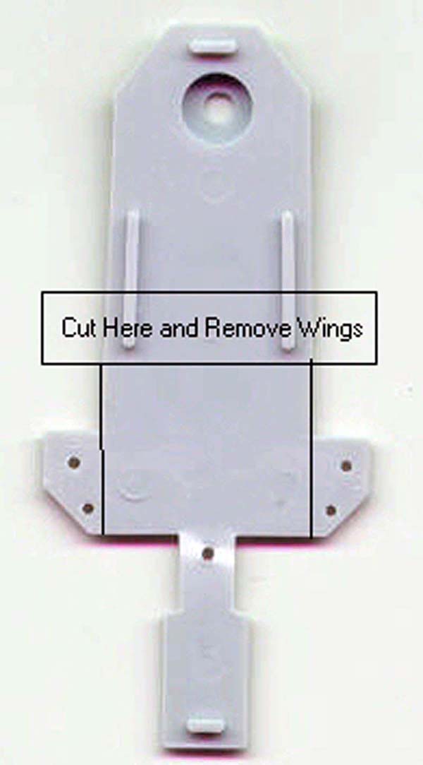
Since the kit represents the Ajax at the beginning of the World War II, the forward superstructure deck had extensions on both the port and starboard side for the Vickers quad 0.5 inch antiaircraft guns. In 1941, this pair was relocated aft of the rear superstructure deck. The plans show that these extensions were removed leaving the deck flush the deckhouse walls below. I trimmed part # 6 to represent this change. I added some strip to form some splinter shields along this new edge.
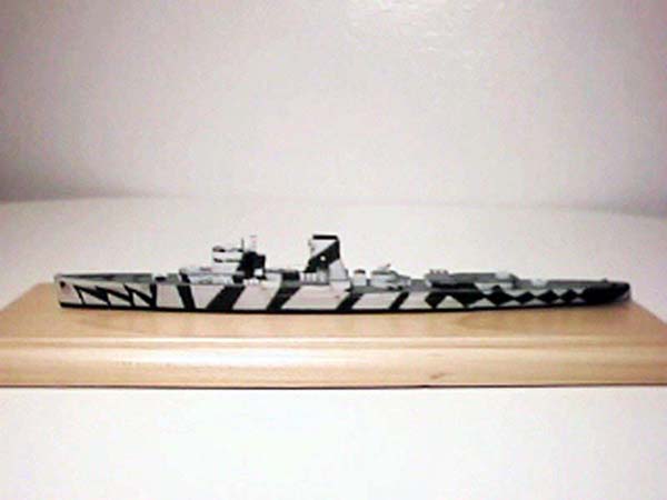
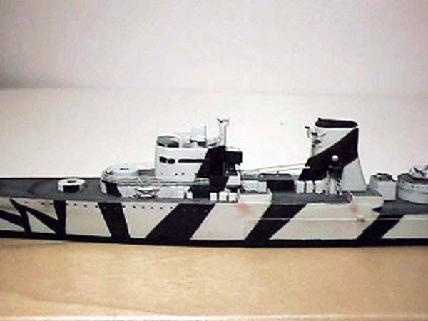
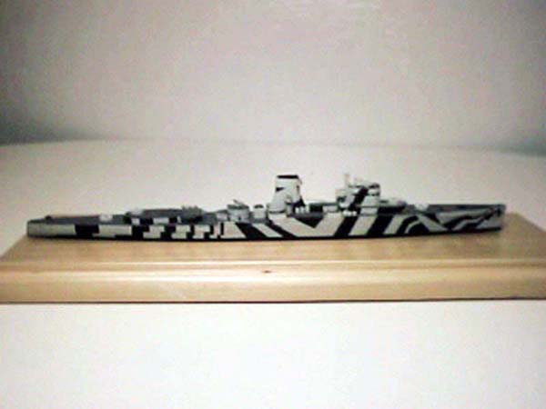
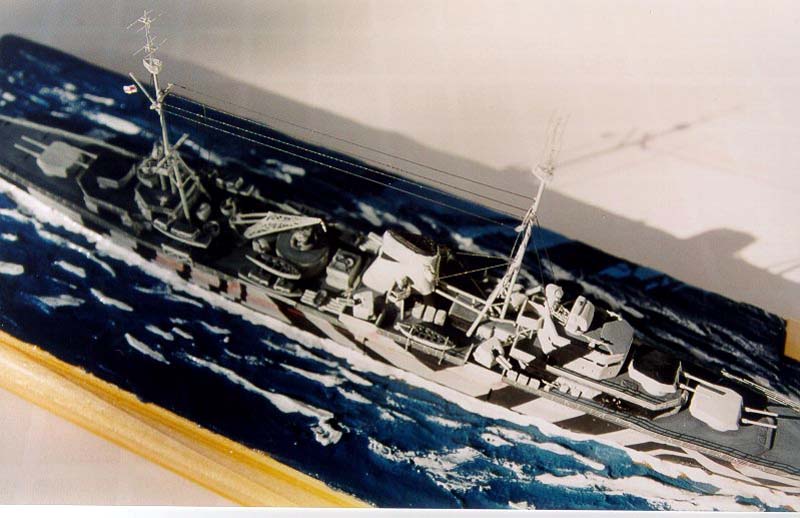
Just aft of the bridge housing there is a small raised square deck with high wall, almost resembling a cube. I honestly do not know the purpose of this platform, but it is there and is quite prominent. I made this addition out of some bits of plastic strip and used the photoetch braces originally intended for the 0.5 inch gun extensions removed in the previous step to support it. In her 1941 fit, the catapult was removed and replace with a quad pom-pom. I used a quad pom-pom from the WEM Pro 600 series of resin parts for this and glued it in place of the catapult. I also replaced the twin four-inch guns with the more accurate and finer versions from the WEM Pro 600 series. The WEM photoetch set provided brass versions of the three Vickers quad 0.5 inch antiaircraft guns. These were a little nerve wracking to make but I did it and they look infinitely better than the kit's out of scale plastic versions. The decided to ditch the awful plastic 6 inch gun barrels. These were warped and not even close to being round. My references show that the barrels were telescoping but the kit's versions were straight runs. I decided to make the 6-inch barrels with some brass tube and rod. I cut the tubing into small sections using my razor saw and a mini miter box and cleaning the edges off with a file. I next cut some thin rod to form the rest of the barrels and inserted one end into the tube and applying a little bit of CA glue to hold them into place. My measurements were based on a rough guess as to how long the 6-inch guns were. I cut the rod a little longer because some of it had to be inserted into the tube. Later after the turrets were painted, I used a black ink marker with a very fine tip to create the illusion of the muzzles. While these gun barrels were a pain to make, they improved the appearance of the model greatly. For this fit, the Ajax had six 20mm Oerlikons installed: two in gun tubs on the quarterdeck, another two in gun tubs on the boat deck just aft of the crane and two more in exposed positions on either side of the forward superstructure. To add these to my Ajax, I took six photoetch 20mm Oerlikons from the King George V set also produced by White Ensign Models. The four gun tubs I created from thin strips of brass that I clipped literally from the photoetch set's fret. I shaped them around a bit of brass rod, making eight in total and choosing the six best. My references showed that there were ready ammo lockers in various locations nearby the secondary and anti-aircraft armament. I decided not to add every single one to my model but a selection that were located in conspicuous places. I added 12 of the larger lockers that held ammo for the four-inch twins. Six were located in groups of three on either side of the funnel just forward of the search light platform and two additional groups of three were located forward of the fore four-inch guns. An additional 6 smaller lockers for the forward 20mm Oerlikons were located three on each side up against the bridge superstructure. A single large locker was located on the boat deck that served the pair of 20mm Oerlikons and also was the end point for some aerial rigging. All of these were made by cutting appropriately sized plastic strip. These little bits of plastic strip went a long way in improving the look of the model and giving the decks a more cluttered look. My references showed that five carley floats were fitted on the Ajax at this time. The kit did not include any, but I am not sure it is because she was not fitted with them in 1939 or that they just decided not to include them. In any case, I took them from one of my Airfix HMS Belfast kits and glued them into position. Two were fixed to the lower part of the bridge superstructure just below "B" turret, two were fixed on top of the torpedo tubes and one was fitted on the roof of the vent housing just aft of the funnel. I glued bits of very thin fishing line colored black with a magic marker to form the criss-cross bracing that secured them in place. In 1941, the fore and main masts were tripods. In the 1939 fit, only the foremast was a tripod. I discarded the kit's masts and built my own using brass rod. According to my references, the tripod legs met the mast at a very high location. Somehow I couldn't seem to make this work with the rigging provided by the WEM photoetch set. So I made a conscious decision to have the tripod legs join the mast at a lower point. In her 1941 fit, two Type 279 radar aerials were fitted on the tops of the masts. The WEM King George V set provides a pair of Type 279 radars, so I took this for use on the Ajax. The KGV set also provides the platforms that would sit atop the masts, but I decided to save this for use on a KGV class model using the Type 281 radar aerials. I made the platforms for the Ajax with bits of plastic strip and trimmed to shape using the ones of the KGV set as a pattern. I used some 1/700 scale rail along the edge of the platform (1/600 rail was too tall) and glued this to the tops of the masts and then glued the radars to the platforms. Thankfully, the Ajax had a rather simple rigging plan. I used very thing brass wire painted Floquil Grimy Black to rig the model. I added just enough rigging to make it appear complex but kept it simple enough to facilitate adding it to the model. The WEM set provides thwarts for the whalers and the cutter. You have to hollow out the insides of the kit's solid boats and to do I used a drill on low speed to gouge out the boats and my Exacto knife and some needle files to smooth it out. It doesn't have to be perfect, as the photoetch thwarts will cover up the edges. I added the photoetch rudders to the whalers but I mangled the oars and was forced to omit them. I used some black strip decals cut into 1mm bits to use as windows on the kit's motorboats. Part IX: Painting The Camouflage Scheme This project was my first attempt to paint any kind of camouflage scheme, and boy did a pick a beauty for my inaugural run! The ship was painted an overall 507C and the camouflage pattern was black. Camo Vol. 1 indicates that the color of the decks and turret tops was not certain for this particular scheme. I made an assumption that this did not differ from the previous scheme, which was 507C, 507B and black. According to Camo. Vol. 1, in the scheme the decks were dark gray (507A), the "B" and "X" turret tops were black, "Y" turret was 507B and other was 507C. I decided to paint the decks 507A and the "B" and "X" turrets black. I used Model Shipways acrylic 507A and 507C from their Royal Navy Colors line, which matched exactly with the Snyder & Short paint chips. For the black I used Testors Model Masters enamel. I had difficulty using the Model Shipways paints. They come as thick as a paste in the jar and no matter which airbrush thinning method I used (distilled water, Tamiya acrylic thinner, denatured alcohol) I experienced problems with the paint lifting off when I removed the drafting tape sections I used to mask the hull. I made an enlarged photocopy of the Ajax port and starboard patterns found in the Camouflage Vol. 1 to make it as close to 1/600 scale as I could. 3M brand drafting tape is low tack and somewhat translucent. I laid a strip of the tape over the enlarged photocopy and I could see the image through the tape. Using my #11 razor, I carefully cut out the sections that needed to remain 507C and applied these section to the hull, superstructure and funnel. I will admit here that the as carefully as I masked out the pattern, it is not a 100% exact match to the artwork in the reference, but certainly close enough. The turrets and other smaller parts that had black sections to be painted I did by hand using a brush. Since I wished to do some degree of weathering, I added a little bit of white paint to some 507A and lightly streaked the sections of the decks that would have heavy foot traffic. This gave the effect of some wear on the decks. I used some rust colored pastel dust (pastel pencil rub against some sandpaper) and lightly added some spots to the areas of the hull where water would run off the deck. I also touched up the area below the hawse holes with some rust. I later used some rust colored watercolors, heavily thinned, to add the effect of streaks to some of the sections. I found that the watercolor worked better than the pastel dust but the pair made a good combination. I also used a combination of black pastel dust and thinned watercolors to add some grime and to highlight some details. I used the watercolor to help bring out the relief-etching on the watertight doors, the vent grills and the anti-aircraft guns. I very faintly brushed some pastel dust over sections of the hull to give a hint of grime and dirt. In some areas I applied a little more black dust for effect. My approach to weathering, especially in a model this small was not to overdo it, otherwise it would look ridiculous and the ship would look like it belonged in a junk yard rather than a shipyard. I guess the adage "less is more" applied here. My final step with finishing up the Ajax was to airbrush the entire
model with Testors Dullcote. This helps to seal in the paint and the weathering
effects, hide the shine from the CA glue and give everything a uniform
look.
They are various methods of making water for a seascape and every modeler has a favorite. My preference is using artist's acrylic gel medium. The brand I have been using is Windsor and Newton. I tacked the finished Ajax on the wooden base using some Duco Household Cement, which is a contact glue. I applied the base layer of gel using a wide and a narrow brush. I smoothed sections of the gel using the brush dipped in some water. I let that base layer dry overnight and then using a narrow brush, I added the wakes and some white caps. I let this dry overnight again before I started painting the water. I have not yet seen the Mediterranean Sea in person (I will one day, I vow!), but I imagine it to be nice and blue. I lightened up some Testors Blue Angel Blue with some white to make a lighter blue as the base coat. I then added some more white and applied this at certain spots, like the edges of the wakes and other waves. To top of the turbulent water and whitecaps, I used an acrylic white craft paint (the brand escapes me) that come in plastic squeeze bottles. It is important to use acrylic white because I found that an enamel white would turn yellowish after brushing on Future clear acrylic gloss. To give the water a "wet" look, I applied 3 coats of Future. As difficult as this build was at times, I truly enjoyed it and
I was quite satisfied with the end results. While not perfect, I did learn
a lot for future projects and she was good enough to take 1st Place in
the 1/500 scale or smaller ship model category at the Long Island Scale
Modeler's Society's RepLIcon 2001. I would like to thank Keith Butterley
for scanning the kit parts I used in this article.
|