|
| History | |||||||||||||||||||||
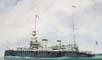
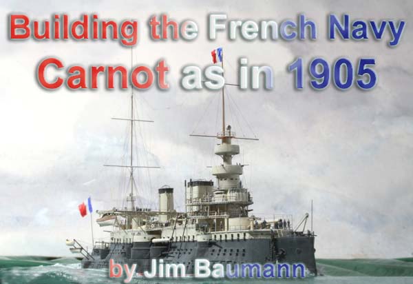
| The French Battleship Carnot was named after the popular
president of France, Marie François Sadi Carnot, who was assassinated
in 1894 in Lyon by an Italian anarchist.
This ship was the last battleship built in Toulon, part of a development series of ships of a broadly similar theme ; each one being( supposedly) an improvement; the other ships being Charles Martel, Jaureguiberry and Bouvet . Laid down in July 1891, she was launched 12th July 1894.
She remained in the Mediterranean until January 1900 when moved to Brest along with Massena as part of the Northern squadron. She returned to the Mediterranean for summer manoeuvres in June. She spent almost two years from late 1900 1902 in the dockyard undergoing repairs and improvements to parts of the underwater structure and was thereafter assigned along with Brennus to the reserve squadron. In August 1905 almost the entire Northern Squadron represented France at the Great International Fleet review of 1905 at Spithead in the Solent in England. October of the same year saw Carnot return to the drydock with further
extensive bilge keel problems.
1907 through to 1913 saw the ship in and out of the dockyards for continuing repairs and brief periods of commission in both the Mediterranean and the Northern fleets as well as being held in reserve fleets Unfortunately by this time Carnot was out of date and was decommissioned on 1 April 1914 to be used as floating barracks. At the end of July 1919 she was abandoned and sold for scrapping, being
finally broken up in 1922
|
|||||||||||||||||||||
| A model of Carnot has to be built . | |||||||||||||||||||||
| Despite her relatively hapless and uneventful career, in
spite of her structural and operational deficiencies she nevertheless represented
the French navy well in her periods of commission.
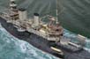
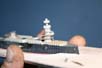
My particular attraction to this aggressive and at the same time quirky looking vessel stems from my fascination of the unusual. The asymmetric funnels and vast tumblehome made a model of this vessel a must-have. The 1/700 kit from the low-volume Japanese resin producer Yumenatu
is not without a number of problems....
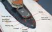
I probably spent over half the long construction time of 3.5 months examining photos and deducing probable deck layouts from the cues presented by the various abovementioned photos. In addition the one on-deck view I found (on the Madrid Spanish Navy website); whilst giving huge amounts of info was of low resolution. I was fortunate in having e-mail access to experienced studiers of French ships of this era to assist me with the probable ventilation and deck layout. In this instance nothing is 100% verifiable, merely likely!
|
|||||||||||||||||||||
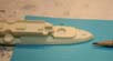
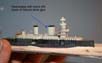
| The actual hull casting was dimensionally ok, nothing much that a sharp
blade combined with endless staring at photos could not alleviate!
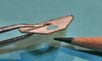
The casting featured a stern that is too beamy from above, far too pointy and missing the characteristically rounded rump. |
 |
||||||||||||||||||||
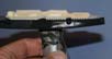
| The superstructure aft was far too wide, impinging on the arc of fire of the adjacent turret. Study of photos gave me relative proportions and a few deft slices of the blade made a more probable shape possible. | 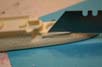 |
||||||||||||||||||||
| The hull was cast hollow with integral crossbraces. To guard against
any future warpage and remove the slight hogging already present I added
a thick styrene base- plate bottom of the open hull. The fairly accurately
positioned but crudely cast hatches were all sanded off . The midships
turret barbette was removed, the platform raised and reshaped before I
softened and re-profiled the hulls tumblehome shape with automotive filler.
The indentations above the aft quarter turret were re-shaped, a bridging
piece inserted to deck level and the deck in-filled to the correct profile.
The deck was then stripped of all cast-on blobs and boxes, planking
made good by scoring with a blade and the hull sanded and re-sanded until
smooth and fair.
|
 |
||||||||||||||||||||
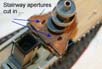
|
The cast on hatches now were all gone--and I wanted to show the ship with most of the hatches open--as images of Carnot static and underway at speed often depict them open. The difficulty of cutting this vast number of square holes accurately was quite simply beyond my methodology on a retrofit kit-build... So I cheated! Black squares of decals strip were applied to represent the hole/void: once this had been complemented with top and bottom hatch lids it began to look fairly convincing.... Getting them all straight and in the correct place was done by steadying lines of adhesive tape and ...mainly eyeball judgement. Relative proportion is everything! |
 |
||||||||||||||||||||
 |
|||||||||||||||||||||
| Once the armour belt made of self-adhesive vinyl tape had been added and subsequently soaked on afterwards with CA for permanence. The ship started to take shape. | 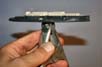 |
||||||||||||||||||||
| Prior to mounting the ship on her base I started on the fwd bridge
structure. From spar deck up all had to be scratch built.
The fwd bridge and aft levels had the distinctive pierced girder sides - these are made of thin PE strips- cut from a much larger PE structure gleaned from a L'Arsenal 1/350 PE set.... (liberty ship ). |
 |
||||||||||||||||||||
| It was a very fiddly pastime as each brass section is separate.
The deck itself was made of paper - cut folded in half to give perfect symmetry, then pressed flat in smooth faced pliers and infused with CA. This resulted a 'scale' thin deck.... |
 |
||||||||||||||||||||
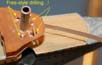
| Carnot had a massive blockhouse quite a long way up the fwd structure,
therefore this required additional bracing through the deck levels to support.
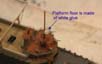
The supporting columns appeared from photos to be square in section. The correct positioning of these was tricky, to obtain alignment the decks needed to be affixed firmly, however the core mainmast made of copper tube was already well embedded and installed. To obtain the correct positions was a process of trial and error- which meant the decks took some punishment from my experimental drilling...The damage was made good by filling with white glue--with the second coat self-levelling for a smooth finish. |
 |
||||||||||||||||||||
| The fwd bridge was making steady progress; the lower and
upper circular platforms were of paper, infused with CA glue wrapped around
a floor of thin PE brass scrap. The lower platform had the gun notches
cut into the paper whilst a flat layout.
When using paper to make splintershields etc--the trick is to pre-curl the paper using a rod of a much smaller diameter than the desired 'circle'. This 'curling' needs to be done on a pad of paper--such as post-it notes- until you reach 'overcurl'... Check the size and cut the strip of paper butt-to-butt--and offer up to your platform base circle; if it is to large--easy-trim it off--if suddenly it is too small.(arghhh!), open it out flat and using you existing strip as a template cut it slightly longer on a new strip... (It can be frustrating at times!) |
|||||||||||||||||||||
|
Once the right size has been achieved I tacked the two butt ends together using a droplet of thinned white glue, which results in a quick tack. Thereafter I tack the circle--which may not be perfectly circular--it is only a soft medium paper-- in place at the join with a tiny droplet of thinned white glue. When this initial tack has set- I work the edges along and over the 'floor' edge.. Once this is satisfactory--I apply very carefully so as not to dislodge it- thin CA glue, which soaks into the paper and makes a continuous bead around the 'floor'-rendering a strong clean joint. The same technique can be used with brass strip (PE fret surround) to make gun tubs and platform splintershields etc--the main advantage in this instance was that paper is easy to cut the gun-arc notches into symmetrically. |
 |
||||||||||||||||||||
 |
|||||||||||||||||||||
 |
|||||||||||||||||||||
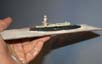
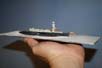
| The ship-model was becoming increasingly hard to work on--the
screw/clamp handle on the base did not lend itself to being laid down.
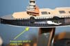
Prior to mounting-I had to add the armoured 'shelf belt' (This is so wide that there are photos of crew members walking along this ledge..!) |
 |
||||||||||||||||||||
 |
|||||||||||||||||||||
 |
|||||||||||||||||||||
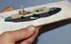
| Thereafter I used the white styrene strip as the white
water-line by virtue of adding a red boot-top
The model was screwed and glued into a pre-cut aperture in some artists watercolour paper similar to the methods I describe here. |
 |
||||||||||||||||||||
 |
|||||||||||||||||||||
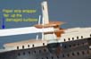
| Carnot was to be shown with the hatches open as I had previously done this on my Massena build where I used paper to make the hatches.... however for a variety of reasons I wanted to try something different. | 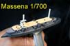 |
||||||||||||||||||||
| Madness prevailed-- and I decided to make the hatch lids--top
and bottom of brass; more accurately I decided to cut pieces of 1/700 ladderstock
into little squares. Getting uniformly clean edges is harder than it sounds...!!
I used scissors to cut the squares, trimmed back whilst holding in tweezers- and then flattened each one in smooth face pliers to remove the curling caused by the cutting. The resulting voids (the centre square of the ladderstock) were filled with thinned white glue. Once set and painted they have quite a pleasing bit of texture. |
 |
||||||||||||||||||||
 |
|||||||||||||||||||||
 |
|||||||||||||||||||||
| For the port side I resorted to using paper as it was very
much quicker and the white of the paper gave a good contrast, making the
made correct alignment to the voids much easier. Once painted the
two sides are virtually indistinguishable.
The aft superstructure was next . |
 |
||||||||||||||||||||
 |
|||||||||||||||||||||
| With few clear well lit photos available, I nevertheless managed to create something that corresponded to what looked like the real thing. Doors and hatches were positioned, some depicted open and the deck-edge beading was made of copper wire | 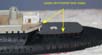 |
||||||||||||||||||||
 |
|||||||||||||||||||||
 |
|||||||||||||||||||||
| I was unhappy with the earlier bridge pilothouse I had made, so it was removed and a new one created using paper, PE and white glue. | 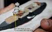 |
||||||||||||||||||||
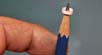
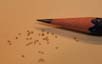
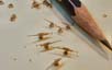
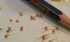
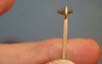
| I spent a considerable amount of time making some of the
small guns for Carnot--she carried quite a lot of QF guns! Many small guns
on many small-scale models are over scale- which is not really noticeable
when positioned on an open deck, but it suddenly becomes very apparent
when there is an overhead deck
I took pains to ensure that the guns are all the correct height--by offering up a PE 1/700 figure and a piece of hand railing. These guns really are quite small! I probably made at least double as many as required, as some were wonky, whilst others left the bench being tweezer-rocket launched into carpet oblivion, while a batch of five drowned in a pool of Superglue... |
 |
||||||||||||||||||||
 |
|||||||||||||||||||||
| I concentrated on the application of the bridge railings
neatly and symmetrically , stairs with separate handrails etc.
I coloured the railings all black with an indelible marker pen first--then painted them from top downwards only with grey--the black implies the shadow and makes the rails-in my opinion-appear thinner. Inter-deck supports made of brass strip gleaned from over scale 1/350 handrail longitudinals added to the intricacy of this stage. |
 |
||||||||||||||||||||
 |
|||||||||||||||||||||
 |
|||||||||||||||||||||
| What appeared to be a disproportionate amount of hours was spent on
tiny details; inter-deck strutting on the aft and fwd superstructure, the
aft binnacle complete with magnets and various vents around the ship, whose
positions were decided after much e-discussion with fellow French ship
enthusiasts.
The aft mooring deck had a variety of small details made and installed,
including vent stacks and a breakwater ahead of the aft superstructure,
with the prominent aft fair-leads being made of 1/350 ladderstock.
|
 |
||||||||||||||||||||
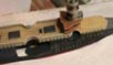
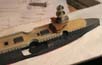
| The fwd square funnel was the slightly sharpened kit item, whereas
the aft funnel in the kit was somewhat undersize and was remade by squashing
suitable size aluminium tubing with a wooden core to maintain the shape.
With the funnels in place the model was starting to resemble some of the old photos.... The 4 x steam pipes had been fitted to the fwd funnel--and the fwd funnel base re-made in-situ after the discovery of an oblique angle photo showing some deck details. The Steam pipes were held a considerable distance off the funnels by
brackets- I made these of thinned white glue forming a 'span'--as the water
evaporated it left behind a tiny bridging piece.
|
 |
||||||||||||||||||||
| After further hours spent staring at zoomed-in photos I suddenly realised
that the upper bridge level was connected via stairs; a glaring omission!
I drilled this delicate and installed deck with a the motor tool set at a very high speed using a small drill bit as a milling piece, so as not to give the drill bit a chance to bite the thin and delicate CA infused paper deck....( I must plan ahead more!) The stairs were installed, guardrails added and the inevitable voids
filled with thinned white glue which self-levelled.
|
 |
||||||||||||||||||||
| A small catwalk twixt fwd funnel and the lower bridge was made and inserted. The tube vents, whose circular lids were made of copper wire circles filled with white glue to dome shape were perched upon brackets made of cut down GMM gold plus hand rail, were made and installed. | 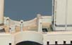 |
||||||||||||||||||||
| After small steam pipes branching off the main pipes at fwd funnel
had been added, more additional hatches and vent stubs installed it was
time to make a start on the gargantuan boat gantry cranes that Carnot carried....
The boat gantry cranes that came with the kit were of no use whatsoever. |
 |
||||||||||||||||||||
| These were a more complicated and sophisticated version of those that
I previously made for my 1/700
model of Pelayo.
The main difference being that virtually all parts of Carnots gantries
were made of pierced girders.
I make pierced girders using a variety of PE ladderstock --which has
the hard internal corners of the PE softened with paint or white glue.
|
 |
||||||||||||||||||||
| Laying stretched sprue across the round apertures to make
them appear shallower created the oval holes in the transverse girders.
After more paint has been applied the holes became increasingly smaller
and the entire structure blended and looked more convincing! I was unhappy
with the oversize holes in my homemade transverse pierced girder. I cured
these by filling the holes with yet more white glue and after 2 minutes
setting time I pierced the film now formed with a shard of brass PE scrap
held in tweezers - the 'setting' white glue opened up into a oval hole
resulting in an aperture some 75% smaller!
The hinged outer halves were made of brass PE scrap cut with scissors--and
drilled using a sharp small 0.3 mm drill bit in a motortool. These then
had flat pieces of fine brass PE scrap glued to their tops to simulate
the rails for the traversing boathoist. The supports underneath these
extensions were made of brass wire, and the large hinge plates made of
paper slivers; the hinges themselves were made with small drops of white
glue.
|
 |
||||||||||||||||||||
 |
|||||||||||||||||||||
 |
|||||||||||||||||||||
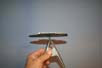
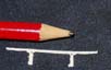
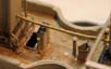
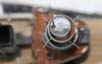
| The deceptively simple aft pole mast consumed many hours. The aft mast was piece of brass tubing, being stronger then rod, with a core of stainless steel wire inserted and CA glue dribble-glued to enable it withstand later rigging loads. | 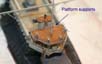 |
||||||||||||||||||||
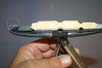
| The mast had a lower platform supported on curved girders; these were installed first and levelled before a platform cut of brass with an oversize hole (allowing wiggle room) was test-fitted | 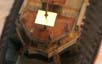 |
||||||||||||||||||||
| The platform had the railings applied in numerous pieces--so as to
ensure that each corner had a stanchion. So as to ensure the side view
of the platform would stay nice and thin the railing was applied to the
outside edge of the platform
The platform had the rails and floor painted off the mast--and was installed using white glue as a slow high tack adhesive as before and once stable I fed some CA droplets to the supports. |
 |
||||||||||||||||||||
| The platform had the rails and floor painted off the mast--and
was installed using white glue as a high tack adhesive as before. Once
stable I fed some CA droplets to the supports.
Above this platform there was an oval searchlight platform. To keep
this platform floor looking really thin I resorted to an old trick in my
technique-locker. I made the railing and attached it to the mast with CA
- the join aft was slightly offset--to allow for the access ladder. Once
set, tuned and wiggled and after having painted the rails the searchlight
platform floor was made using thinned white glue spanned across from underneath
as a film.
|
 |
||||||||||||||||||||
 |
|||||||||||||||||||||
| Having added supporting struts and awning stanchions and life rings made of flattened copper wire circles I continued with fine detailing by adding the overboard discharge pipes along the hull. | 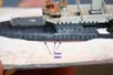 |
||||||||||||||||||||
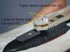
| The forward funnel base had vents and flaps added using decal stripe for the voids and paper for raised lids. | 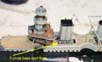 |
||||||||||||||||||||
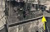
| After being sent a secret photo of Carnot taken from a raised vantage
point, it transpired that the shape of my aft funnel base was
incorrect and it also needed to be furnished with vents and flaps.
Not wishing to remove the glued and pinned funnel and risk damage to
the funnel or the steam pipes I retrofitted a new funnel base of brass,
the angled facets being made of brass slivers and white glue.
|
 |
||||||||||||||||||||
| The above photo also confirmed some of alterations to venting arrangement
being required, with further tubular vents being made alongside a square
item with an angled square cowl.
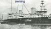
Even under way Carnot often carried a large furled awning slung between the binnacle vent structure and the aft funnel and then another awning slung between the fwd face of the aft funnel to the aft face of the fwd funnel. It is a prominent feature--and was suspended from overhead cables.
|
 |
||||||||||||||||||||
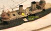
| It was made by bending some brass tube into shape and fixing into place, and then adding the texture to simulate the furled awning with semi-dried white glue, once painted and with hoists installed it did look convincing. | 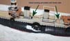 |
||||||||||||||||||||
 |
|||||||||||||||||||||
 |
|||||||||||||||||||||
| The hull had accommodation ladders aft of midships leading to doors in the hull-- photos show these to have been open sometimes when under way--I guess ventilation. I made my door 'aperture' using a bit of black decal stripe to simulate the void; the door was made of paper--with a pinhole to simulate the porthole within. The platform was also made of paper attached with varnish. | 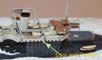 |
||||||||||||||||||||
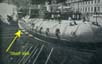
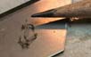
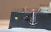
| Not a single boat from the kit was any use. The boats used
are a mix of modified Combrig, shortened and narrowed WSW, ancient (scrap)
Airfix and scratch built..
The boats appeared to mostly have covers on at all times...- I made these using white glue and acrylic matt paste, smoothed and shaped with a wet brush. The boats all had a band of exposed varnished wood around the gunwhale, masking these neatly would have been beyond my patience threshold!! I made this 'timber' feature using a strip of black decal stripe. Once dry the decal gave just enough of raised edge to give a clean demarcation line. In addition, on the steam launches the top and bottom of this strip has a strip of fine brown stretched sprue assed to simulate the beading. The covers over the cockpits of the steamboats were made of paper-- photos of the real thing suggest that the canvas was draped over hoops. The boats were stored on wheeled dollies, which could be moved underneath the gantries for hoisting overboard to the water. The open boats midships were stacked inside each other; I hollowed away the thwarts to make the upper boat appear less 'perched'. The Canvas covers were outlined in sharp pencil with the under-hull ties being drawn. More than half the 3.5-month build time was taken with study and analysis of photos, the finding and interpreting yet more details being simultaneously joyous and frustrating. I noticed two admiralty pattern anchors with folded crossbar located aft of the mid-ships battery. PE was too thin and I had nothing remotely right in shape or outline
of the anchors
so made my own from scratch using brass wire, shards of
brass PE and white glue for the weights. The large stocked anchors either
side of the bow were also made, the massive square stocks this time made
of a piece of the smallest micro-strip styrene I could find--and then split
it in half with a blade. Flukes were made of shards of brass cut with scissors;
with 95% of the cut 'flukes' sailing away through the air
-never
to be seen again! The 'fattening' of the casting around the crossbar aperture
was done using white glue. Once painted the anchors do look the part!
|
 |
||||||||||||||||||||
 |
|||||||||||||||||||||
 |
|||||||||||||||||||||
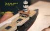
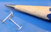
| The fwd anchors were hung, the supporting bracket housing
and access ladders installed. The fwd hawse-pipes when the ship was underway
had cover plates; these were cut and filed to shape.
The anchor handling deck had its rails installed; these were stanchion
and cable--and photos showed the cables to be generally slack and saggy.
Having installed the 'straight ' rails they were then stretched and given
a gentle sag with the tip of fine tweezers, rolling back and forth twice
on each horizontal segment.
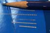
One of the things that often lets down other otherwise nicely built 1/700 models is small platforms. When a floor is fitted, be it plastic or resin, or even brass and with the rails fitted on top of the platform the edges are way over-scale and the model can end up looking clunky. Drilling holes in thin brass, and square ladder aperture can be challenging without distorting the outside edge. Combined with the difficulty of getting clean paint demarcation lines on the in-side of tiny circular or square platforms I have circumvented this by pre-forming the rails to a chosen shape, gluing to the mast the mast and infilling the base of the pre-painted railing with white glue; once set it dries clear and if painted from the underside perfect paint demarcation will result with a very thin platform effect as demonstrated earlier on the aft mast searchlight platform. The foremast searchlight platform was complicated by the need of the mast to pass thru an asymmetric position aft-of-centre; which meant I could not stick the rails to the mast. Requiring a ladder access aperture further complicated this part.. I solved this by bending the rail and butt- joining the circle. I cut
some 1/350 handrail using the longitudinals and a stanchion to form it
into a U- shape. This u-shaped supporting bracket was glued around the
mast, and the rails stuck on at the aft end with matt varnish so that the
metal supporting struts were level with the bottom of the handrail, this
being facilitated by gluing the aft end first and then adjusting the angle
of the model until the rail circle balanced level with the fwd butt ends
which were then tacked with CA at both ends.
|
 |
||||||||||||||||||||
 |
|||||||||||||||||||||
 |
|||||||||||||||||||||
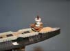
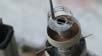
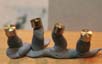
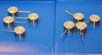
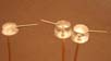
| The main armament of Carnot was set to be a problem The kits supplied items failed to convince, the castings being the wrong height, diameter, flat-topped and not truly circular in some instances. I immediately decided to make new turrets; unfortunately I was unable to achieve neither sharpness nor the repeatability in shape I desired using my manual manufacturing methods; nor having the skill-set to operate a lathe. Of course not actually owning a lathe proved a further handicap! | 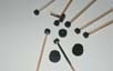 |
||||||||||||||||||||
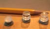
| German based gun and mast manufacturers BMK
ModelWarships.com sponsor came to the rescue.
They obligingly converted my sketches and measurements into a technical drawing for my approval, whereupon they then proceeded to turn all 12 differently sized turrets on their CNC miniature lathes, along with all gun barrels. The main turrets and wing turret and barbettes were turned in Acrylic, this being a new medium to me. The 4.5 turrets, in two batches of subtly differing heights were turned in solid brass. All have a beautifully subtle domed tops--and all are identical, something that I was unable to achieve manually. |
 |
||||||||||||||||||||
 |
|||||||||||||||||||||
 |
|||||||||||||||||||||
 |
|||||||||||||||||||||
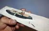
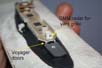
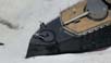
| Much study of photos elicited a hatch on the foredeck underneath the gun barrel. The photos showed these hatch lids to often be open underway. I made my hatch using Voyager doors and paper triangles for the ends, lightly dusted with graphite. | 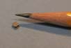 |
||||||||||||||||||||
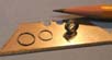
| The turrets all had slim asymmetric doors that sealed the aperture in the turret to guard against heavy seas. I made mine using some PE rings ( L'arsenal) that I squashed on a corner of smooth faced pliers after cutting in half; this resulted in the interesting asymmetric shape--and was repeatable. | 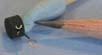 |
||||||||||||||||||||
| The colour demarcation line between the grey and black was hard to mask level accurately and consistently. I preferred to paint by hand and bridged the edge with black decal striping and when set I painted the sharp edge of the decal strip black to match the remainder of the turret. The turrets were installed, the sighting hoods made of styrene rod rounded and split in half and the sighting apertures in the hoods were made of slivers of decal strip after painting. There were further triangular/cloverleaf shaped sighting apertures in the fwd faces adjacent to the barrels; these were also made of slivers of decal stripe. | 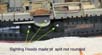 |
||||||||||||||||||||
| The final addition of small details such as gussets and
brackets was bringing the model to its conclusion. The solitary range-clock
on the aft face of the fwd mast was sourced from the WEM Iron Duke PE set;
painted white and brushed over with graphite dust to lift the relief-etched
numbers. The small Maxim (?)guns were modified from WEM saluting
guns with fatter bases and a new barrel. Awning stanchions
of fine 1/350 handrail longitudinals were made and installed on all decks.
The anchor-handling crane was a centre-pivoted design with a flat metal
circular traversing track enabling the crane to rotate fully. The track
for this was made using thin lead wire formed into a spiral, from which
circles were sliced; the best of these was selected and compressed between
two Stanley blades in a small vice to give a circular flat circle! The
crane itself was made of wire, brass and styrene bits.
|
 |
||||||||||||||||||||
 |
|||||||||||||||||||||
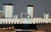
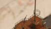
| The distinctive funnel grilles were made of stretched sprue--the result being very much finer than PE. | 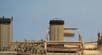 |
||||||||||||||||||||
| Carnot carried her nameplate on the railings of the aft superstructure. The drawing has been made--now I need to contrive to print it accurately 2.4 mm ( approx 1/8) long . Fortunately I can retrofit it once I have found a successful printer! |  |
||||||||||||||||||||
| All the railings used were GMM Goldplus superfine, some
with the waterways removed and some had several coats of brown paint to
simulate the wooden cap rail.
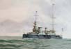
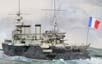
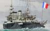
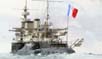
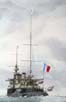
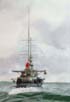
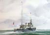
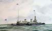
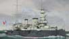
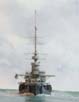
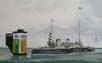
The crew consists of a mixture of GMM and Eduard PE figures. The thickening with white glue, bending into pose and painting of the figures occupied a considerable amount of time, but was essential to the creation of the scene in which I wanted to depict the ship. .August 1905 . the Grand Fleet review at Spithead , Solent in Southern England. Continuing the Entente cordiale France sent over the major units of the Northern Squadron. The ships entered the Solent flying the French "Tri-colouer" on the fore- mast and the very tall stern ensign staff, with the courtesy White Ensign hoisted to the very top of the WT mast at the mainmast. Carnot is cleaving the waves off the eastern side of the Isle of Wight closing the coast.
For many of the French sailors its the first time they have seen "Angleterre" and her mighty fleet of battleships at anchor .... Carnot's crew are straining at the port-side rails to see the magnificent
array of ships for the first time
..
|
|||||||||||||||||||||
|
I must express my sincere thanks to: Renaud Aimard without whose extensive collection of rare images and knowledge I would have been unable to complete this model satisfactorily Carl Beetz whose analytical skills and mentorship prevented me from rushing headlong into a series of photo-interpretative errors with consequent poor results fro the model! Steve Foulkes for stainless steel masts and PC/graphic help.
|
|||||||||||||||||||||
| In conclusion. | |||||||||||||||||||||
| Given the lack of plans this kit manufactured by Yumenatu, despite
the lack of accuracy in details is nevertheless is a valiant effort,
It is far from being an easy build to obtain a satisfactory result .. As a consumer, I would be happy to pay more for a kit that had greater
casting quality and scale fidelity.
|
 |
||||||||||||||||||||
More
of Jim Baumann's work.
Updated 2010

© ModelWarships.com