| In the previous article I talked about some of the basic hull parts. In this part we'll talk a little bit about the two decks available for the kit (the kit deck and a laser-cut wood deck from Nautilus), techniques for both, and the lower hull. | |||||||||||
| The Plastic Deck | |||||||||||
| The plastic deck that comes with the kit is split into three sections with separate pieces for the elevators and elevator wells. Since very, very little of the interior would be visible with the elevators fully down no hangar deck is provided. The detail is on par with the earlier Essex release and leagues better than the CV-8 Hornet kit. Fit between the sections is a little better in my opinion, although the same problems exist. | Click images
to enlarge |
||||||||||
| The main problem is that keys that are molded into the bottom of the joining edges prevent an exact fit. The forward deck piece, for example has two small keys that fit outboard of the single, large key molded on the front edge of the middle deck piece. These outer keys aren't quite low enough and have the effect of curving the center portion of the deck upwards so there is a noticable step on the outer joint. The end result is a noticable gap and lots of work filling and sanding! We can actually save on a lot of work later however, if we do a little bit of work up front | 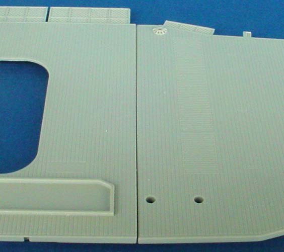 |
||||||||||
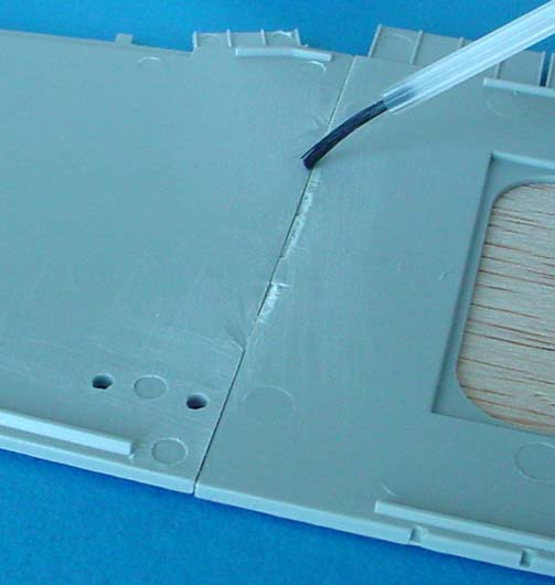
| Since the keys caused problems, I removed them. Less than a minute with a razor saw and all of the edge protrusions from the front joint were gone. I then snipped off the remaining plastic on the underside with my flush-cutters (similar to diagonal wire cutters but oh-so much better) and sanded down the remaining plastic with a sanding stick. I also sanded the edges a bit to remove a bit of a step that the molding process had left. | 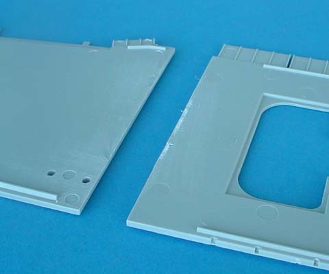 |
||||||||||
| Now, the next step is to set these pieces face-down on a flat surface so that they are lined up straight, and with the surface of the flight deck even. We don't really care if the lower section isn't level as we won't be seeing this area once it's glued down. We have a bit of an inconvenience in that there are raised details on the deck that will prevent us from keeping it perfectly level if you set it down on your workbench, but there's an easy work around. Find any flat, thin strip of material; I chose store-bought balsa wood. If we lay the pieces down on this it will elevate them enough that the raised details won't cause mis-alignment. | 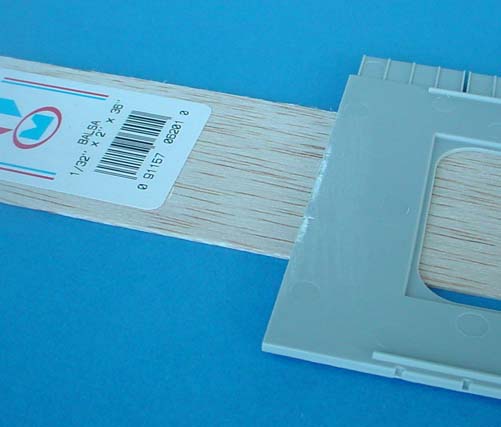 |
||||||||||
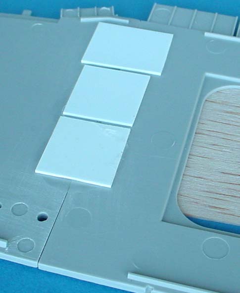
| As the series below shows, we want to line up the two pieces on the "jig" and start gluing the center. We start in the center simply because that's where the support is. You want to use a normal amount of glue, but don't flood it as we dont want it to reach down to the wood. As I got a segment glued together I glued .040" sheet styrene to act as a doubler so that any bending motion wasn't focused at the joint. I also made sure not to glue these doublers where it might interfere with the fit of the deck to the hull. | |||||||||||
|
|||||||||||
| As you move along you can move the wood so that different areas are supported and even. Past a certain point however the raised parts of the deck will get in the way; you have two options here. One is to let the deck dry for a bit and then flip it over. We can now line up the remaining joint by eyesite and glue them in place. The other would be to cut a thin strip of wood off the end and slide it under the joint so those areas are even as well. | |||||||||||
| Once I had the deck glued I waited an hour or so for things to set and dry and flipped it over. There was still a little gap in the deck but it was much less than it would have been otherwise, and we now have a joint that's much easier to fill and sand. After flipping the deck over I brushed on some more liquid cement to get the side that glue might not have reached. This also had the effect of filling in some of the visible joint left. | |||||||||||
| An optional item you may want to deal with are the safety nets on the sides of the deck. The Gold Medal Models set will contain replacements for them, so I'll cover removing them here. Even if you're not going to remove them you may want to read this section as there are relatively easy enhancements one can make. | |||||||||||
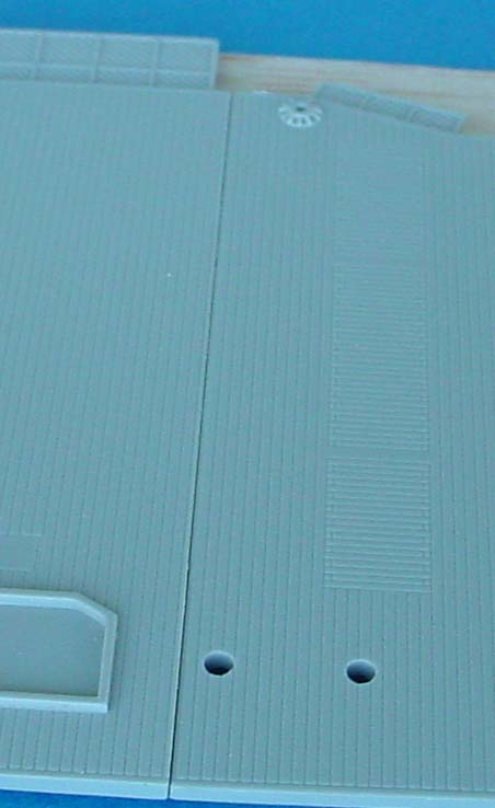
| The nets were easy to remove with a simple hobby knife. Set the tip of the blade at the corner between the net and the deck and draw it across a couple times to score the plastic. After a few passes you may cut through in some areas but not others; keep focusing on the areas you haven't cut through yet and draw evely along the length of the score until you've cut through all of it. Some nets came off after as few as three passes but others were a little thicker and took up to ten passes. | 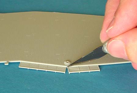 |
||||||||||
| Another Option is to use a razor saw. For better control I prefer to hold the saw by the back of the blade and not the handle. I also will usually only make one pass at a time, always in the same direction, then move it back and start over. I find this gives me better control and makes it less likely that I will cut too deep or too far. A disadvantage of the razor saw is that its length causes difficulties in some areas such as where there are inclined ladders down to the boat pockets or where the deck has a concave angle to it. | 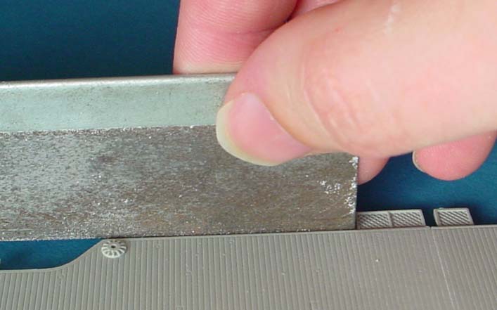 |
||||||||||
| This leads to an interesting possibility. As you can see to the right, it's possible to cut most of the way through without going all the way through. Even if you cut through the nets there are some extra molded-on supports that wil remain. | 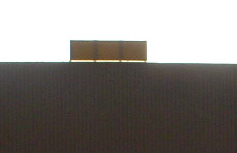 |
||||||||||
| The reson that this is of interest to us is that on the Lexington these nets weren't actually mounted horizontally as on the kit but angled upwards so that if someone who was rolling along the deck had a good head of steam going, the net would serve to stop them as opposed to acting as a trampoline to bounce them farther out. Once you have cut down most of the safety net you can bend the net upwards a bit and glue it in place with liquid cement. Looking at pictures of kibutzing sailors on Saratoga, I would say the proper angle is about 10-15 degrees up. | |||||||||||
| Wood Deck | |||||||||||
| Soon after the arrival of the kit Nautilus Models relesed
a laser-cut wood deck for the model. The wood was not used to replicate
wood decking but as an inexpensive and easy to use medium. Resin would
have suffered from fragility, warpage, and shrinkage and brass from cost.
The basewood used is of a much different color than the fir used to cover carrier decks. Because of this, and because it is wood, the deck will need to be stained for color as opposed to paint. Users of Acryllic paints should know up-front that their paint will warp the wood and that the work around for this is to stain BOTH sides evenly to try and cancel out the warp. Nautilus advises that the deck be attached to the model with cyanoacrillc glue (aka super glue). I would actually advise an intermediate layer be used due to the uneven hull sides of this kit; although the warpage is minor I don't think CA glue would lend itself well to the task of holding sections just right and dropping in a drop of glue. Additionally, my preference is to support the deck a tad as mine was slightly warped across the beam and I wanted to both strengthen it and remove the warp. I started off gluing down the deck as you can see below, but in retrospect I believe it would be wisest to stain the deck first as any glue on the deck will soak into the wood and change the staining properties there and thus the look. It is possible to sand the surface a bit if this happens but you won't get much back as the glue soaks into and permiates the wood I wanted to reinfoce the deck, but I couldn't change the thickness without it looking odd. I chose .010" plastic; .005" was too thin and might tear when glued and .020" was too thick. I taped the two deck sections together and then a sheet of Evergreen stock to the edge of the bow of the deck to hold it in place. I then drew an outline around it with a sharp pencil. This I just used to see that I was lined up as I went along; I wanted my cut to be as close to the outline of the deck as possible. |
|||||||||||
| I then lightly scribed the basic outline a couple of times. In some places I scribed all of the way through, but around the inclined ladder platforms at the edges of the deck I just scribbed enough to leave the outline of the edge. Once I had the entire length if the piece of sheet plastic scored or cut I removed the tape and deck and then went over the areas that I hadn't cut with a straight edge to finish them off. | 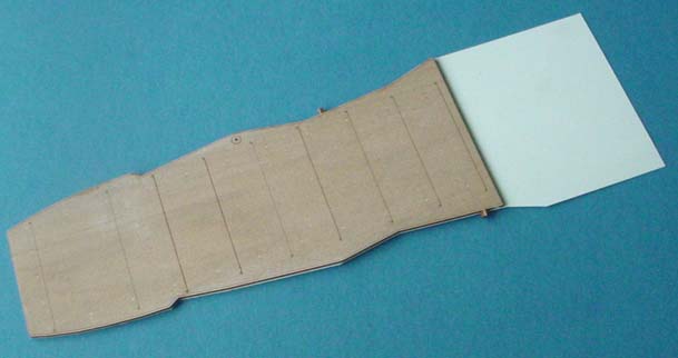 |
||||||||||
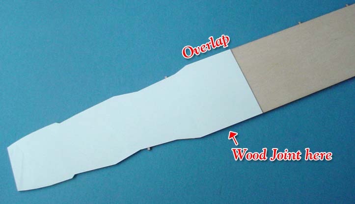
| This left me with a thin backing that extended past the joint. I then
taped the bow edge of the two pieces again to line them up and then extra
tape further down the deck to hold the alignment perfectly. I removed the
tape from the forward edge and lifted the plastic in this area up, exposing
the wood underneath. After squeezing a line of glue near the edge the plastic
was pressed back down and rubbed in such a manner as to move any excess
glue to the stern end of the deck.
After the glue had dried I removed the rest of the tape and lifted up the other end of the plastic. It was then a pattern of dripping some glue down on the wood near the previously applied glue and pressing the plastic back down, rubbing it so as to spread the glue outward and aft. The wood soaks up most of the CA glue but be carefull as any excess will drip off and glue the top of the deck to your work surface! |
 |
||||||||||
| Once the deck was down on the plastic it was time to look at the superstructure. It was apparent that the trailing edge of the kit's island was rounder than the outline on the deck and knowing that the deck had come out just after the kit, I wanted to make sure there weren't any issues. I started by examining the wood pieces that are provided as aligning plates for the island and stack structure. Each was wider than the outline on the deck but each fit the kit parts nearly perfectly. | 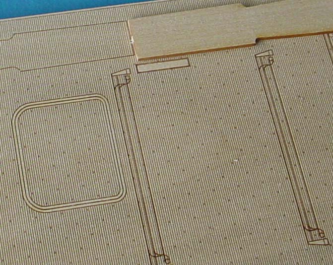 |
||||||||||
| Next the plate for the stack superstructure was placed on the deck to examine how it placed the stack on the deck. As you can see to the right, when the piece was centered over the plate outline the stack base is shifted to starboard and parts hang out over the edge. In this case the plate wasn't used; the base was centered over the outline on the deck, which you can see inside the base. | |||||||||||
| I next tried ignoring the outline and lining the superstructure up with the deck on the starboard edge. The good news is that the stack outline doesn't appear and is still covered, the bad news is that so is part of the torpedo elevator and arresting gear! This is actually not quite a show-stopper, for reasons I'll cover a couple of paragraphs down, but it is something to be careful about. | |||||||||||
| Another caveat about lining the stack superstructure up with the starboard edge is that it pushes it further inboard than the bridge superstructure ahead of this. It is noticable when looking straight down but as you see from the below picture once you have more of the fiddley bits mounted you really can't tell from the side. | |||||||||||
| The picture to the right has both superstructures on deck; the forward part is aligned to the center of where the outline shows it to be and the aft stack superstructure is aligned to the starboard edge and you can see how it's right on the torpedo elevator. If we pushed the forward part to port so that it lined up we'd cover the edge of the forward elevator. However, it doesn't look bad, and as I said it won't be too big of an issue if you're willing to not use all of the kit parts. | 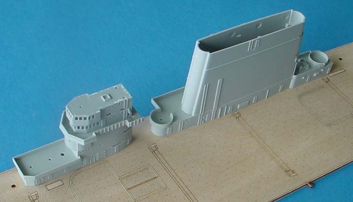 |
||||||||||
| The "T" shapes that were sticking over the edge are actually misrepresented; this area was a passage way and Trumpeter added the support to make it easier on the modeler. Every PE set I have seen (Gold Medal Models, Tom's, and Yankee Modelworks) has replacement supports that will be a little more difficult to put on, but what it will allow you do do is remove that support that pushed them over the edge andessentially fudge the location a bit. You can push the structure further starboard so the torpedo elevator and arresting gear aren't covered, you don't have parts hanging over the edge, and you have the correct walkway! It is "teh win!" as forum monkeys like to say. | |||||||||||
| So my big advice here is to not glue these plates on before doing some serious experimenting. Test fit; It will pay off in the long run. | |||||||||||
| After all of this I decided to go with the plastic deck. "Why," you
ask? Well... for a multitude of reasons. I wanted to keep this "simple"
and "fast" so I elected to try and bypass the potential problems. I believe
that one can use the deck and come out with a superior representation,
but the kit deck isn't actually that bad on its own and is definately an
option. Playing with the fit of the two, back and forth, revealed that
the Trumpeter hull actually has a lot of subtle rippling lengthwise in
the upper section. I think this is related to what caused the rippled sections
over the boat pockets but I don't have the means to measure defelection
and the like. I had by this point become aware of another issue that I
myself had caused with mis-alignment and was a little leary of trying to
fix one side only to make things worse on another.
The last issue I have unresolved with the wood deck is that of painting. I'll say right off the bat that I'm a wood neophyte; I've built balsa models but I've never done a wood ship, etc. The instructions say to stain the deck with a non-acryllic paint, or that if you must use acryllic, to stain both sides to even out the resulting warp you'll get from doing so. I stained the deck with successive coats of WEM teak thinned out 75% with thinner. It takes the stain nicely, to the point that the wood grain is still visible after about 7 coats and is showing no signs of going anywhere any time soon. I decided to call James of Nautilus Models, the manufacturer of the wood deck. What he's now advocating is that the modeler first seal off the wood with a clear finish such as model master's flat or Minwax (A suggestion of Ron Smith, who is going to experiment). Once again, stay away from a water based seal as we're trying to protect the wood from moisture warpage. This should also seal off the grain somewhat and then you can paint over the sealed surface with paint like you would any other plastic surface. James recommended spraying fore and aft as this will give a subtle streaking pattern in the same direction that the tires wore the deck in. I would agree, but add that it's only one part of the techniques that would be used to portray a weathered deck. |
 |
||||||||||
| Back to Menu
On to Part 3 |
|||||||||||