| The recent 1/350th
USS Lexington CV-2 release has been one that many people have been
anticipating for a long, long time. I've always loved this design, and
with no hangar deck trap to fall into I thought this would be a nice, simple
build.
Only problem was that I was unemployed at the time and the price tag was a might steep with no job. Enter a birthday and amazing wife and we have the start of a good write-up. But once I started into it the build was too easy, too fast. That AMS monkey was on my back and chittering away. So to feed the worm I decided to do a series on building the Trumpeter Lexington "stock." So I bring you..... Or I promise you Honey, this one will be stock! |
|||||||
| In this case I mean no serious modifications or conversions. I will be add the Gold Medal Models Photo-etch when it's available and perhaps the Nautilus Laser-cut deck. Otherwise I will resist the temptation of all those happy sheets of styrene and my Chopper. | Click images
to enlarge |
||||||
| Initial impression in the box is very favorable. As I have a friend with a model shop I've seen four of them recently opened and I've noticed something similar in all of them. There are rounded-off openings both port (four) and starboard (one) near the top of the hull for the boat pockets and the thin plastic on the top bulges outwards as if the hull was sagging (nautical term where the center of the ship sags downwards in relationship to the bow and stern, The opposite is hogging) and applying pressure on the top of the hull. In one case one of these pieces had broken from the stress. I laid my upper hull out on a flat surface and found no evidence of warp in it, so I'm still a little unsure as to what causes this. Thankfully, it's not that difficult to fix. | |||||||
| Molding is generally crisp although there is a little flash here and there on edges that needs to be addressed. For the most part this appeared on my kit on the bottom of the hull and around the openings in the hull, both the series of open windows and doors on the starboard side as well as the open AA galleries near the bow. The hull itself has a couple of molding depressions (otherwise known as sink holes) but most of the ones I've run into are covered by sponsons; the one exception to this is on the edge of the bow near the waterline. There are a couple of molding "artifacts;" odd protrusions here and there and bumps around the starboard side openings but they are easily removed. | 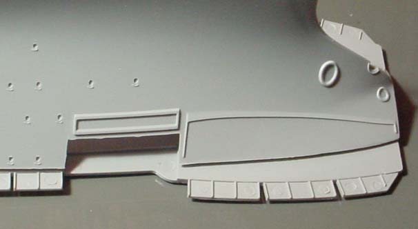 |
||||||
| One thing that has been mentioned is poor fit between the upper and lower hull sections. This is dead on; I measured a maximum gap of 3/32" on one side when the other was lined up. It starts out as a minor mismatch at the bow and stern and gradually builds out as midships is approached. The distortion lies not with the upper hull but the lower; tdemonstratedstrated by a good fit between the flat plate for waterline builds and the hull. | 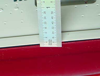 |
||||||
| There is considerable resistance to any change by both pieces; the lower hull is a very thick plastic and its compound curves make it very rigid and the upper hull has lateral stiffeners that keep the hull spread to the correct width. Squeezing the upper hull so that it matches the beam of the lower takes effort and produces the distortion to the lateral supports you see in the thumbnail to the right. I have no confidence in any glue or solvent's ability to hold these two pieces together without severe cracking beyond a year or so. | |||||||
| One solution that has been suggested for this is to slice the lateral supports so that the hull can be squeezed in and made more narrow. While this would work, it would essentially transfer the fit problem and not negate it. Instead of having a large gap between the two hull sections there would be one between the hull and the flight deck. One might try spreading the upper hull area out to match the flight deck but I could see other problems arising from this solution. | |||||||
| My thought at this point was to try and weaken the bottom hull's strength so that it would be easier to pull out and would exert less squeezing force on the joint. To do this I wanted to break the support that the different sections gave each other. I did this by sawing down to near the keel in different areas. This did make it easier to push the lower hull sections outwards but I think it would be best to cut some brass tubing to the approximate size and file it to fit the inner hull as additional support. I cut a length of tubing about 88mm (3 & 7/16") long and it mostly worked. The port side fit beautifully but it was now apparent that the step on the bottom hull that serves to align and strengthen the joint was actually either too thick or two far out on the starboard side and was preventing a flush fit of these two parts. I suppose one could merely shave or cut this off but by this point I had had enough and decided just to use the bottom plate and do her waterline! | |||||||
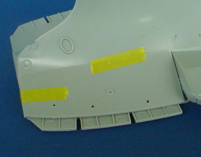
| Thus energized, I turned to the pieces that go on the sides of the model's hull. Early steps focus on adding the sponsons and galleries of the hull. These parts have generally fit well, albeit there have been edges that needed some cleanup with a sanding stick and knife. Sponsons fit well against the hull when some basic test fitting and flash cleanup is performed ahead of time. B6 seemed to jut out too far for me so I cut off it's aligning lines and positioned it myself. B3, the aft sponson on the port bow, also had a gap at the front between the sponson and the deck that I later figured out was one of the aligning lines; when I shaved off the forward half-inch of so on the opposite side's piece it fit much better. As you can see in the right picture, there is a small gap under one of the doorways; this seems to happen here and there on these galleries. | |||||||
| There are a couple of steps I would switch around in retrospect or due to fit testing that I'd like to suggest for other builders and I will cover those in the course of the build. The two front "brows" from the refit that increased the width of Lexington's forward flight deck posed a problem for me that I will get into more in-depth a bit later. I would wait until after the deck is in place to glue them on. The aft gallery deck has four vertical pieces that the builder is instructed to attach after the deck is glued to the hull; I would actually do these ahead of time as it much easier to fill all of the punch marks and alignment holes on the bottom of the deck before it's glued on to the hull. | 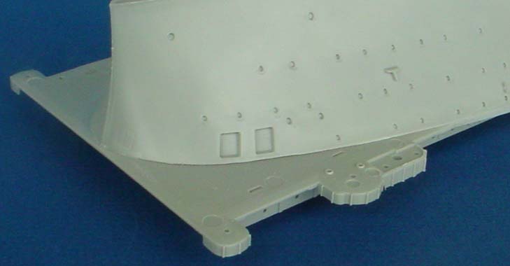 |
||||||
| Otherwise the only warning I have is to take care removing the gallery decks themselves; Trumpeter consistently molded the spue tree right into the splinter shields between the stiffeners and careless removal will lead to some interesting clean up work with putty and a jeweler's file. | |||||||
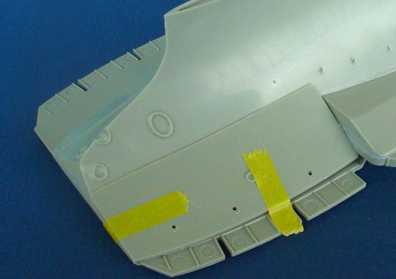
| After the bow sponsons the next area I worked on were the inserts amidships for the launches, known as boat pockets (some of which were turned into extra AA galleries by the Battle of Coral Sea). The openings for these were the areas I mentioned above that were bulging out. I tried two different ways of fixing them. The first was to glue the bottom and sides of these in and leave the bulged area alone, and once those areas dried go back and glue the top and hold the bulged out plastic against the inserts until it had dried. On the smaller openings this worked well, but on the larger ones there was enough extra length that it wanted to ripple at some point of the length. Once the deck is on this shouldn't be evident and test fitting has shown no fit problems because of it. The second method I tried was to cut the plastic with a razor saw; in doing so a portion of the "extra" plastic was removed, and once the insert was glued in I could glue the two parts together without any ripple. This does cause a little extra work however in that it leaves a nice cut that has to be sanded and polished. The second boat pocket in the thumbnail to the right is the one I cut; the others were pressed into place and glued down. | |||||||
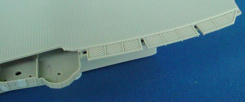
| Now, on to the "brows" at the bow of the ship. These were added in 1937 when the flight deck was widened up front. Trumpeter molded these as separate pieces, with what I'd described as ramped alignment lines on the hull. They seemed to fit okay but a bit sloppy. There was a little gap in the front and I wanted to make sure that they were aligned correctly so that the deck fit. I decided to tape the deck to the hull and align them that way before using liquid cement to glue them into place on the hull. While this solved one problem, it brought to light another. | 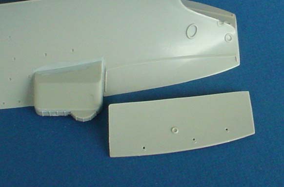 |
||||||
| If you line up the starboard extension, part B17 so that it fits flush with the hull, it actually extends out past the end of the deck. To make sure this wasn't just some slop in the fit I glued all the sponsons and boat pockets in for some extra rigidity and then taped the full deck down on the hull, taking care to make sure it was absolutely lined up right. Same effect. In playing with it I discovered that I could line one edge up, either the deck edge or the hull edge, but not both. If I lined up the deck edge there was a gap between the hull and the brow, but it wasn't too bad and could be filled with putty or milliput. From the top, the molded-on safety nets hide most of the ensuing gap, so this might not be much of an issue with you, but if you're planning on replacing these with photo-etch or using the Nautilus wood deck you should structure your building steps around this. | |||||||
|
|||||||
| With the exception of the lower hull and bow extension brows, these parts go together fairly well. Stay tuned; next time I'll be talking about the flight deck, comparing the plastic deck to the Nautilus laser cut deck. | |||||||
| Back to Menu
On to Part 2 |
|||||||