 |
|
|
| Back to Menu | |
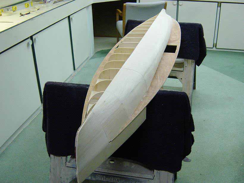
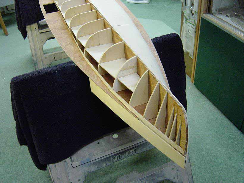
| Here we have the Wolverine in the early stages of construction. I like to use the "plank on frame" method of hull construction, which is illustrated here. I started out by fabricating the keel from 1/4" luan plywood. Actually closer to 3/16" in thickness. This gives me a strong center section to work off of. I then cut all the frame members or bulkheads from 3/16" balsa sheet stock. After marking the locations for the bulkheads on the keel section, I then attached them, one side at a time. Since this assy. is over 7 feet in length, it moves back and forth quite a bit due to the natural flexing of the plywood. A good way to stiffen everything up was to add the main deck now, before sheeting off the hull. I fabricated the main deck again from the luan plywood and drew centerlines where the keel is to be placed, then attached the keel to the main deck, after dry-fitting to be sure all is straight and level. In these two photos the sheeting process has begun. I like to use bigger sections of sheet balsa rather than narrow planks wherever possible. This speeds construction time. I used 3/32" balsa here, again sheeting one side at a time. To get the sheeting to bend around tight curves in the hull without splitting, I soak the sections in hot water for a couple minutes to get them pliable enough to bend easily around the bulkheads. Note in the second photo I have added balsa sheet at 3/16" thick in between the bulkheads before the sheeting process was started. This was to further stiffen the structure and for strength. Openings in the main deck are for the paddlewheel assys. Also note in photo #2 I have added the upper fwd. bow section, again with frames and sheet balsa. | click images
to enlarge |
 |
|
 |
|
| This photo shows the port side stern area. Note that here the balsa sheeting will not work in all areas due to compound curves. I then use narrow strips or "planks" to cover these areas. You can see I have started a little bit of wood puttying to fill in gaps between the sheeting. I do this as I go along as part of the "rough-in" process. | 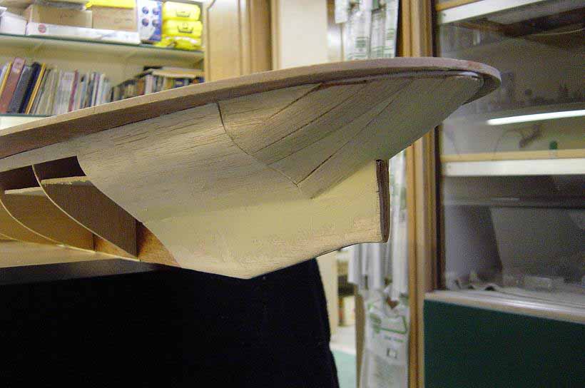 |
| Dead-on view of the bow. The hull is still pretty rough at this stage of the build. To get the bow correct, I'll eventually add a thin piece of styrene plastic attached to the very center of the plywood keel. This plastic piece is shaped so it matches the bow outline and comes fwd. about 3/16" of an inch. The fwd. end of the plastic will be the edge of the bow. Autobody filler is then used to shape the rest and fill in gaps after the hull is coated with epoxy resin. Note how the upper bow area has been shaped into the rest of the hull. Wolverine had a fwd. rudder, which has not yet been added. Compare this photo with photo #11. | 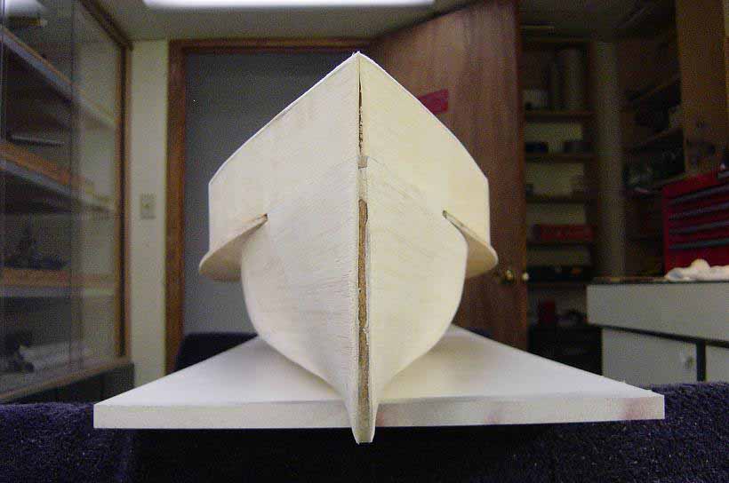 |
| Stb. side view of the hull structure. Hull is now fully sheeted off, sanded, gaps were filled and I am ready to apply 4-5 coats of Epoxy Marine Resin. Note the cut-outs for the paddlewheels on the main deck. The other cut-outs you see are actually hand grabs to make it easier to move the 7 foot hull around. I'll now start to coat the balsa wrapped hull with the resin, sanding between each coat. Once the wood has been sealed and sanded smooth, I'll begin adding coats of lacquer based automotive primer/surfacer. This product builds fast and sands easily to further take out imperfections. Many coats will be applied. I'll then start the final shaping of the bow and stern areas, plus any other areas which need help with auto body filler (bondo). I'll then prime and sand again until all areas are smooth and uniform. Then it's on to paintwork. | 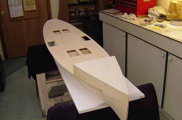 |
| Hull up-side down here looking stb. side aft. Note the bottom has been painted hull red and the black boot-topping has been added. The bracing to support the main deck has been installed using styrene strips. There is about 200 of these braces along the underside of the main deck. The portholes were first drilled out and then small rubber o-rings were added before the bracing was added. This area above the boot-topping is still in primer coat. The construction of this bracing was first laid out using a template I made to get the correct spacing. Small plot marks were made where each brace attaches to the hull. Holes were then drilled into the hull at these plot marks. I then added all the long parts of the brace using .060 square styrene strips, one end going into the previously drilled hole, the other end attached the edge of the main deck. The advantage of this process is that the long section of the brace can be "rough cut" so that all do not have to be cut exactly to the correct length. Just cut long, install in hole and pull to edge of deck, then attach. Goes faster than you would think! Next, I went back and drilled holes for the diagonal and vertical pieces of the brace. Coming back again, I added the short vertical pieces first and then the diagonal ones. These were also "rough-cut" then nipped off with some p/e cutters after they were glued. Lastly, a small strip styrene "cap" was added where the other three pieces come together. There are over 800 individual pieces on this bracing alone. More bracing comes later. This is nothing'!! After all bracing here was added I then applied more primer. | 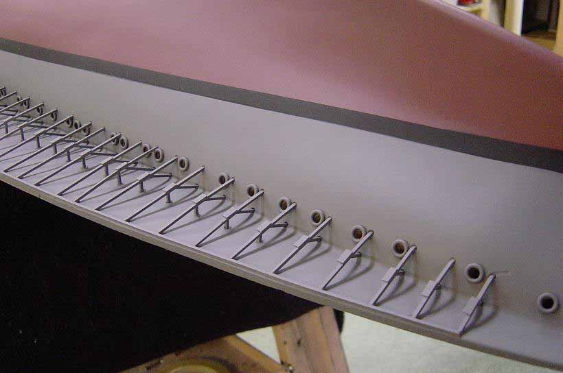 |
| Starboard side bow view here. The front of the bow has now been finished and all bracing is installed under the main deck. Other small items have added such as the portholes, anchor hawses, etc. Note the forward rudder has been added. I cannot stress enough the importance of prepping the hull, or any other large assy. before final painting. Sanding, priming, filling, shaping, all adds up to a nice looking piece if you do your homework as I have done here. Gets a little boring at times but the end result is worth the work!! Would you agree?? | 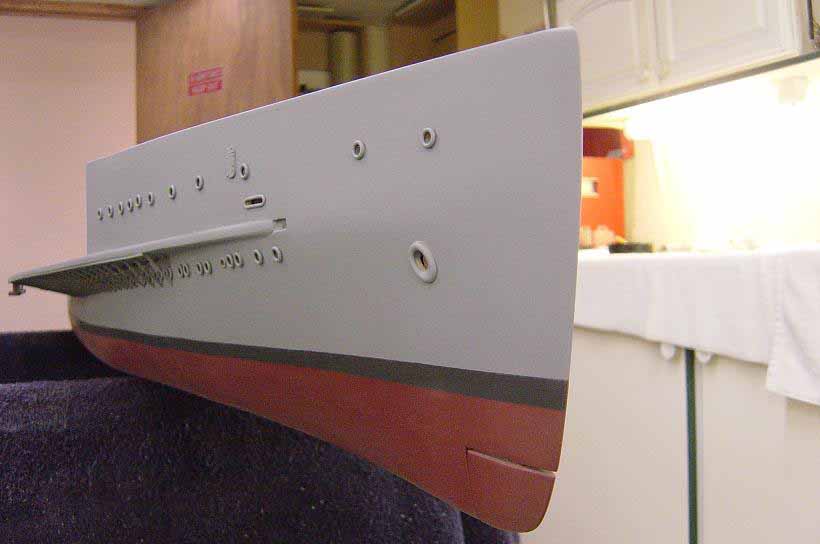 |
| Bow shot again, up-side down and port side. Hull above waterline now finish painted Sea-Blue (5-S). Testors Model Master Marine Acrylics used here. Testors enamel used on hull red . All painting was airbrushed except primer coats. Note the fwd. rudder. | 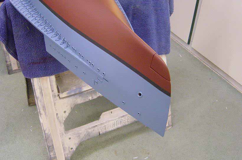 |
| Starboard side stern view here. Hull above waterline still in primer in this photo. Main rudder was cut and sanded to shape out of a solid piece of 3/8" balsa sheet. The blister you see is a towing, anchor hawse cover, to the best of my research. Compare this photo with #3. | 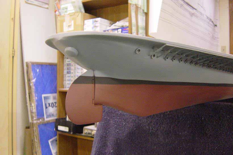 |
| Bottom view of the hull. All areas here now finish painted. Note the paddlewheel guards have been added. Again, careful prep work pays off. | 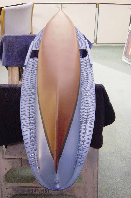 |
| Bow view again, dead on. Compare this with photo #4. A little more shaping to do here. Anchor hawse's are cast metal from Blue Jacket Shipcrafters. | 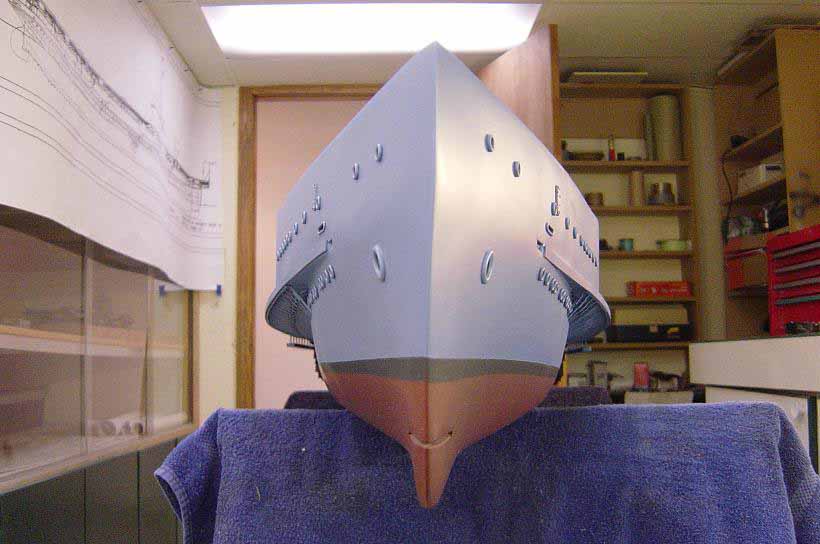 |
| Here's a shot of the finished paddlewheels assys. There are over 200 parts to each wheel. It would be difficult to describe every operation in building these from scratch but I'll try and give you some idea of the construction sequence. First, I had real good drawings of the wheels I obtained from Doug Wilde, a friend of mine who lives in Maryland, and he is close to the National Archives in Washington, D.C. First step was the outer rings. The side view plan was glued to poster board then the rings were cut out. The center of the ring is where the driveshaft will go so I cut a circle there, to accommodate the driveshaft. Note there is an inner and outer ring with bracing between. This is all one piece. When I cut out the circle in the center of the ring, the arms beyond the inner ring can be bent the the correct angle inward which will attach to the center hub (driveshaft) braces. The center hub has 11 braces that attach to these arms. After I fabricated the driveshaft from 3/8" wood dowel, I then added all 11 braces to this shaft. Then the rings were attached. I had added small shafts to the inner side of the arms on the rings which hold the buckets or paddles. The paddles were made from thin sheet balsa topped with thin sheet styrene. The brackets on these paddles were cast from a mold I made in resin. Each paddle has two brackets which hold the paddle to the wheel. After the paddles were fabricated, I spread the rings on the wheels apart slightly, and installed the paddles on the small shafts previously installed, sandwiching the paddles between the rings. They are not glued, but are movable. I then added the articulating mechanism. There's a lot more to it than that, but this will give you a general idea. | 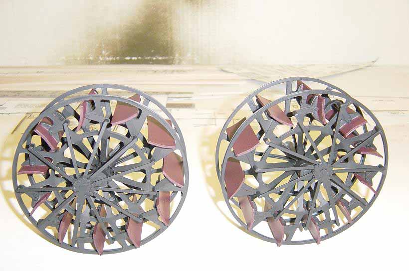 |
| Here's the hull again starboard side. The areas above the waterline are not finish painted here. Note I am checking the installation of the wheels here making sure all lines up correctly. So far, looks good. | 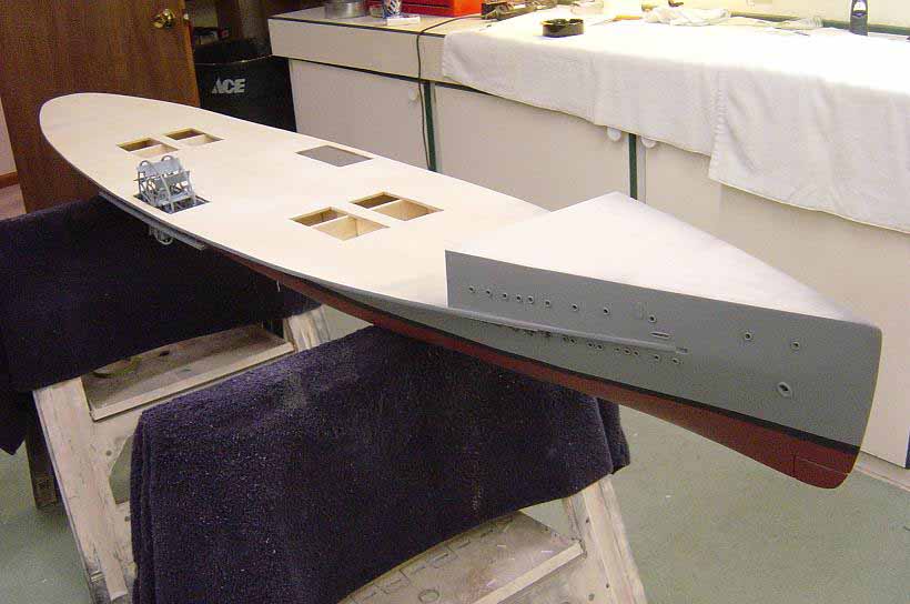 |
| A closer view of the starboard side wheel here. It is not yet permanently installed at this point. Again note the guard just below the main deck. | 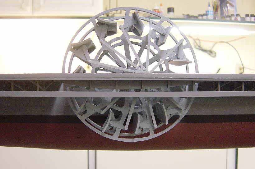 |
| Starboard side again but a little different angle. I'll do this same procedure of alignment of the wheel on the port side. When all looks good, I'll finish paint the wheel assys. and mount them. | 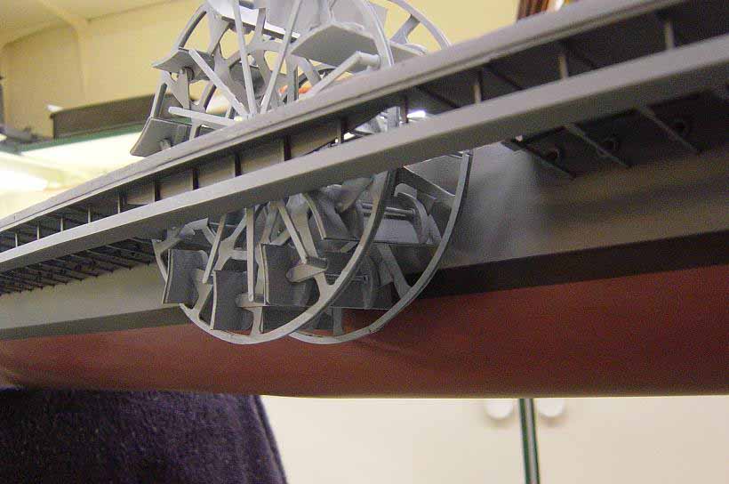 |
| Starboard side again showing the wheel painted and permanently installed. Hull finish painted in this shot also. | 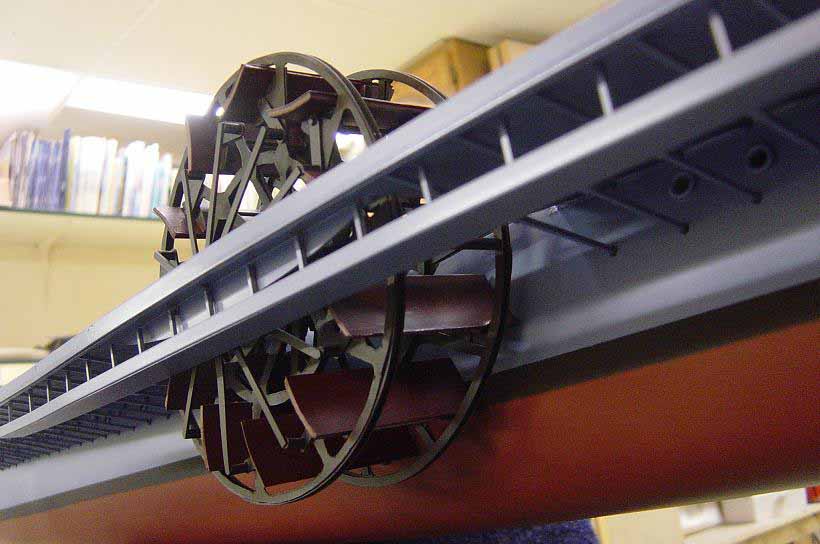 |
| This photo shows the paddlewheels now mounted and I have added the main deck "planking". The main deck is not actually "planked". It is made from .040 walnut veneer and the plank lines are cut in with a laser, done by a company near where I live the specializes in laser cutting wood. I cut the correct shape of the main deck from patterns I made directly from the plans, then attached the veneer to the plywood deck using contact cement, after the laser cutting of the veneer sheets was finished. The same procedure was done on the flightdeck, more on that later. | 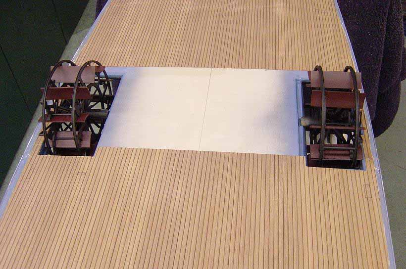 |
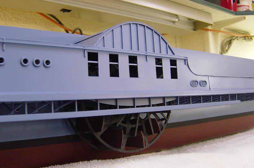
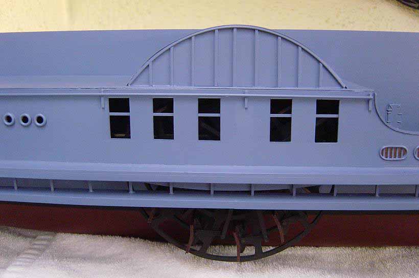
| I have now added the walls of the main deck superstructure and the starboard side wheel house in this photo. For the walls of the main deck superstructure, I again cut patterns directly from the plans and fabricated the walls from .040 styrene sheet. After dry-fitting to be sure all was correct, I built a frame to support the walls out of 3/16" stick balsa. The details on the walls, such as portholes, hatches, etc. were added before the wall were attached to the balsa frame. Note the cross braces between the walls, again from balsa sheet stock. The wheel house was built in the same manner as well as the addition of the bulwarks. Note that all is now painted and the deck is stained where it is visible. | 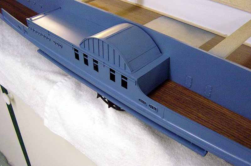 |
| This series of photos shows various angles of the completion, mostly, of the main deck superstructure, wheelhouses and related items. Again, all this is styrene product over wood frames. Other details were added after the installation of the main parts, but most was done prior. Easier to get at that way! | 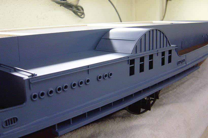 |
 |
|
 |
|
| Well, that's it for part one! Hope you can get an idea
of how things progress on a big model such as this. I'll try to detail
as much of the construction procedure as I can as this article continues.
As always, comments or questions are welcome!! Stay tuned for part two!
Best to all and Happy Modeling,
|
|

© ModelWarships.com