| Hello again fellow ship modelers! In part one of the USS
Wolverine build I discussed the construction of the hull, main deck, paddlewheels,
and related items. It is now onto the bridge and the flightdeck areas,
which will be reviewed in this Part two article. Let's check it out!! |
|
|
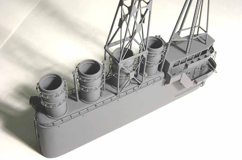
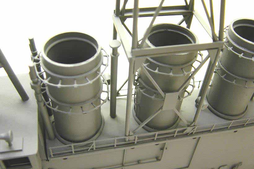
The main section of the island is cut out and shaped
using a solid block of white pine. After comparing this section to the
plans to make sure all was correct, it was time to add the other items
to this main section. Holes were drilled for the funnels first using a
drill press, and then all portholes were drilled out. The funnels are actually
one half of a spring loaded toilet paper roll holder!! Amazingly enough,
these are the exact diameter I needed, and have some cool raised details.
When scratchbuilding, one must investigate all avenues!! Funnels
were cut to the correct length, allowing for the depth of the holes already
drilled into the bridge itself. I then detailed them out one by one using
modified galvanized wire mesh for the grab rings, plastic ladders, and
some other parts I had in my stash box. They were then mounted using five
minute epoxy adhesive. Steam vents and the whistles were then added. The
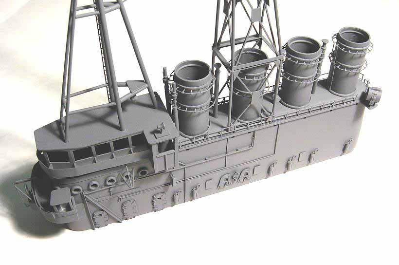
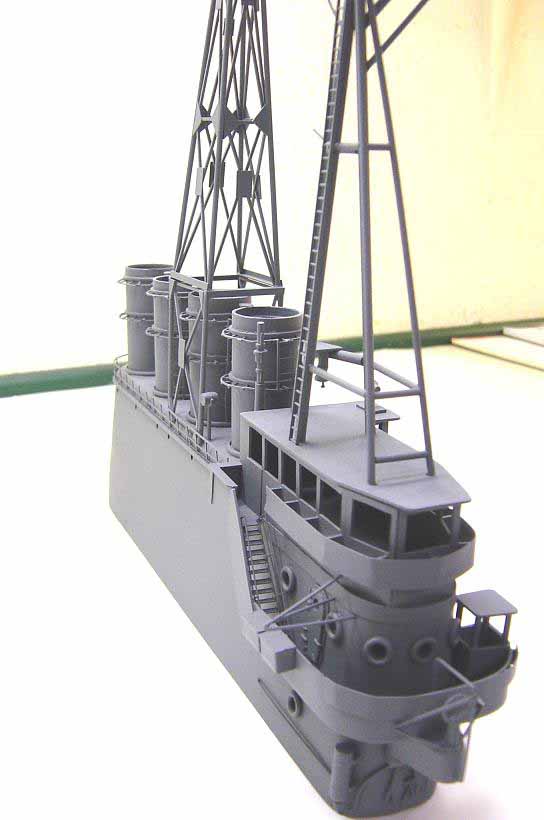
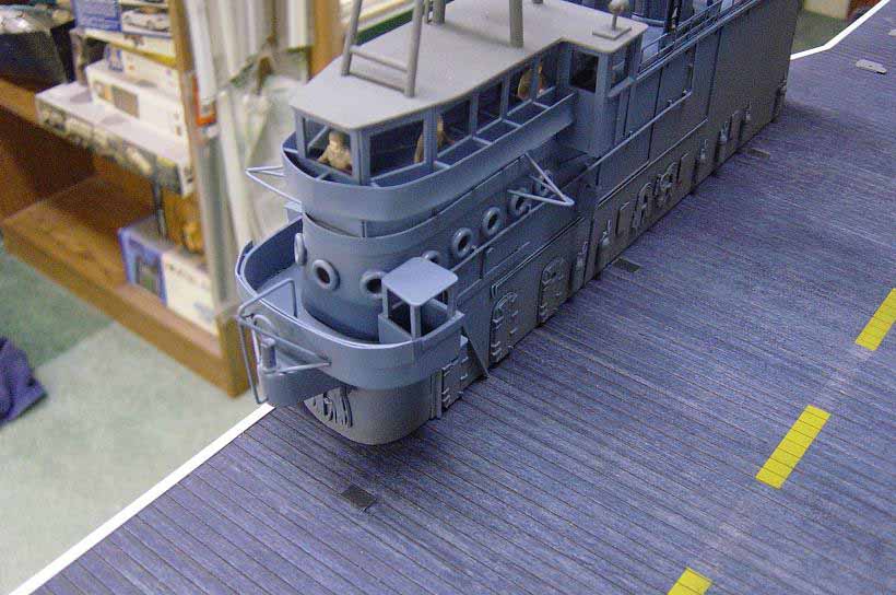
next step was to build the enclosed command bridge. When Wolverine was
first commissioned, this command bridge was open and exposed to the elements.
It was later enclosed as depicted on the model. The command bridge enclosure
is fabricated from sheet styrene. I built all the walls first, and then
cut out the window openings where clear plastic would be applied later
after paint work was complete and figures were added. I then made the roof
where the forward mast will be installed. The roof is not permanently attached
yet. Next, the RDF platform was added, again using styrene product. Stairway
to the command bridge is p/e brass. Other items are cast metal. The next
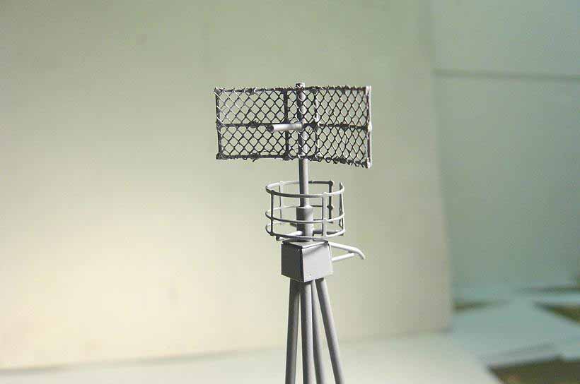
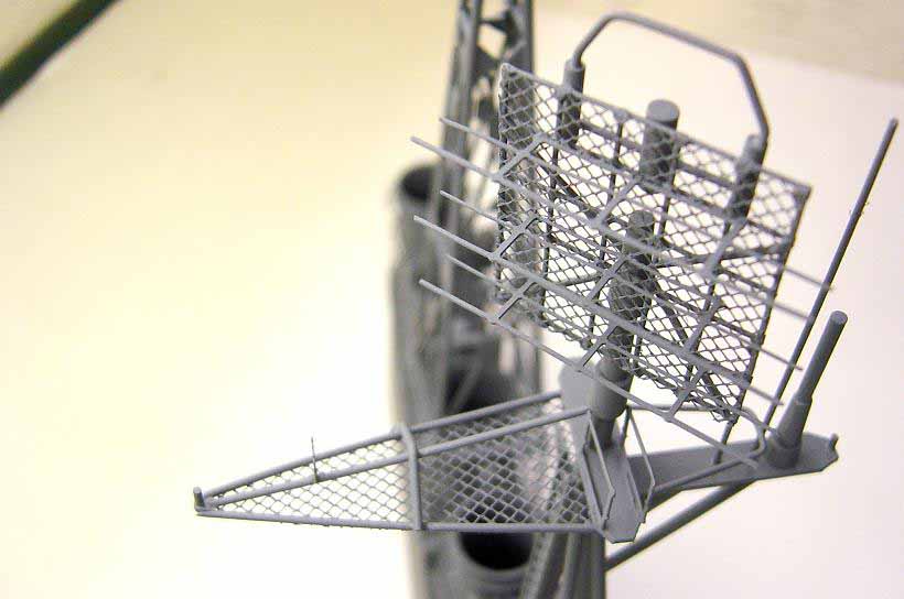
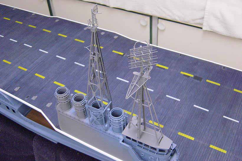
step in the island assy. is the two masts. Wolverine started out with just
the fwd. mast with an early version of air search radar on the very top.
The navy attempted to add other radar's to this forward mast assembly,
but found that neither the mast nor the supporting island assembly would
support any more weight. Therefore, the second mast was added, to accommodate
more radar assemblies, and the island was strengthened using steel angle
iron, visible on the port side of the structure. Late in the Wolverines
career, both masts were removed and a single, heavy duty steel pole mast
was installed. Getting back to the two masts, I was fortunate enough to
have detailed photos of both of them. Construction of the masts involved
the use of styrene rod, strip and angle stock. The radar's are made from
galvanized wire mesh, modified P/E brass parts and nylon netting. The forward
mast was built directly on top of the command bridge roof, while the aft
mast was built on the island itself. After all looked good, final paint
work was done and the roof on the command bridge was attached, after figures
were installed inside. Other details were then added such as fire hoses,
extinguishers, porthole rings, valve wheels, outriggers, searchlights,
railings, etc.
|
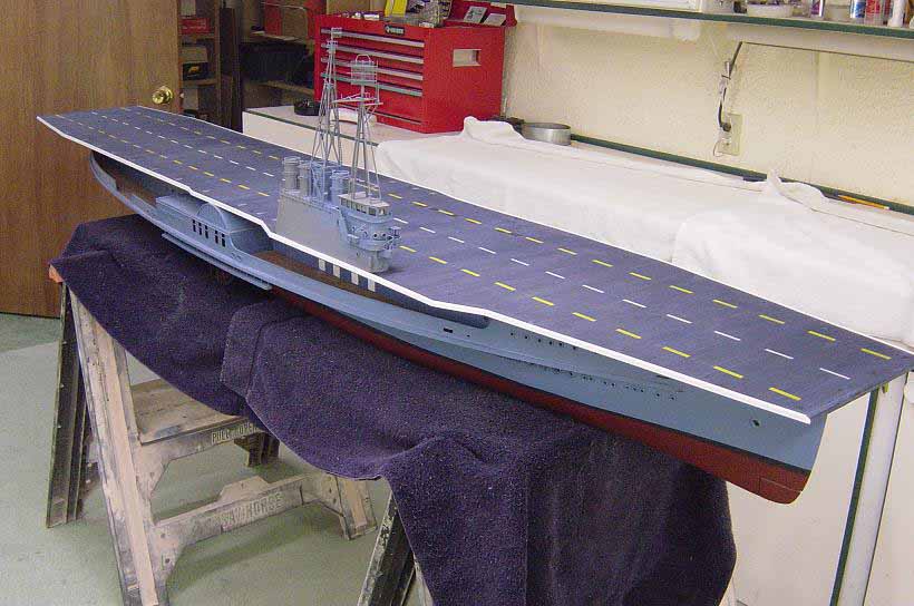
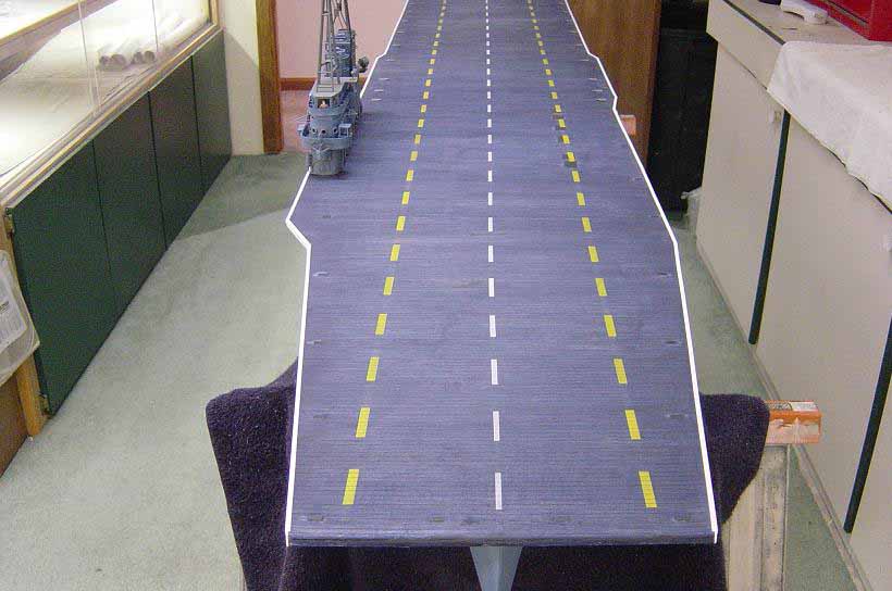
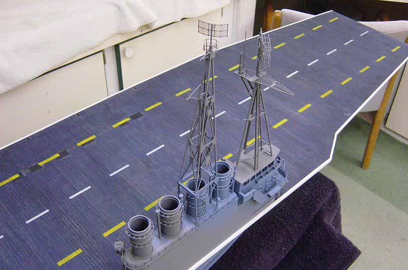
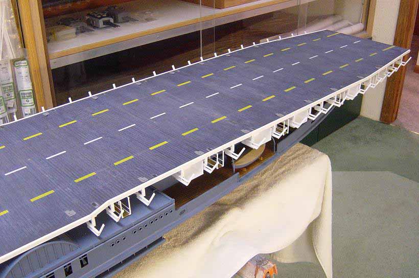
In this next series of photos I have begun work on the
flightdeck. Note that the planking has been installed and stained the correct
color and I have airbrushed all the dashed lines on. Also the flightdeck
lights have been added as well as the arrestor wire and barrier arm stations.
At this point, the flightdeck and the bridge are not permanently attached,
as a lot of work needs to be done yet. Also note that the bridge has been
partially painted due to the fact that the inside of the command structure
is painted and figures are installed first before the roof is permanently
attached.
|
The flightdeck is a model in itself. There is a massive
amount of framework beneath the deck that supports it. All would have to
be fabricated. A time consuming task at best! I started out by cutting
out the flightdeck from one piece of 3/16 plywood sheet, the same as the
main deck. The bottom of the deck was then painted with some white latex
paint in order see the layout lines for the support structure. Next, the
flightdeck was placed on the hull structure to check all centerlines and
to trace out the outline of the main deck superstructure walls where the
supporting truss assemblies would stop. After I was satisfied that all
was straight and on center, I removed the flightdeck add began adding all
the plot lines in pencil where the support structure would be mounted.
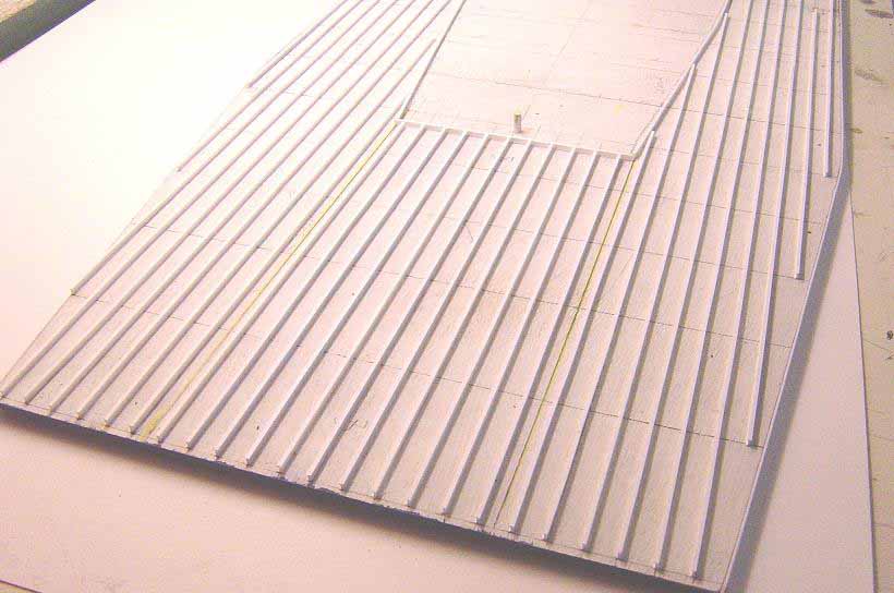
It was now a good time to add the planking to the flightdeck. Instead of
using individual planks, I decided to use thin veneer here as was done
on the main deck. The plank lines are burned into the veneer with a laser,
look quite realistic, and save much construction time. Two sheets of veneer
would be used, each sized 24x 48, allowing the laser cut plank line to
run the same direction as the grain of the veneer. These sheets are then
attached to the plywood flightdeck using contact adhesive. Excess material
is then removed, and the edges are sanded smooth, straight, and uniform.
Styrene strip was then added around the entire edge of the flightdeck.
The veneer decking is then stained the correct dark blue color (flightdeck
stain #21) which I had mixed up by a local paint store. Once the stain
had dried thoroughly, it was then coated with clear, flat lacquer. The
dashed lines on the flightdeck were then masked off and airbrushed white
and yellow. Other details are then added such as the arrestor wire stations,
barrier arms, flightdeck lights and tie down tracks. These details are
all scratch built using styrene product again. More detail will be added
here later in the build. It was now on to the support structure.
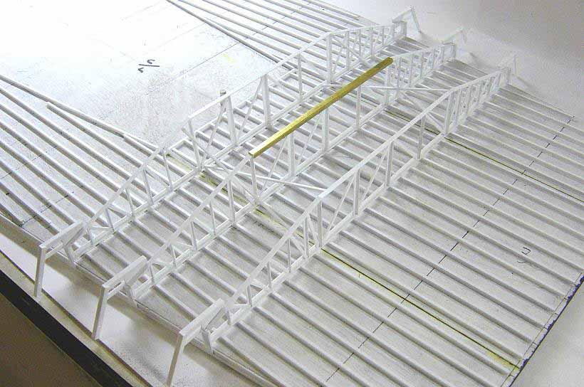
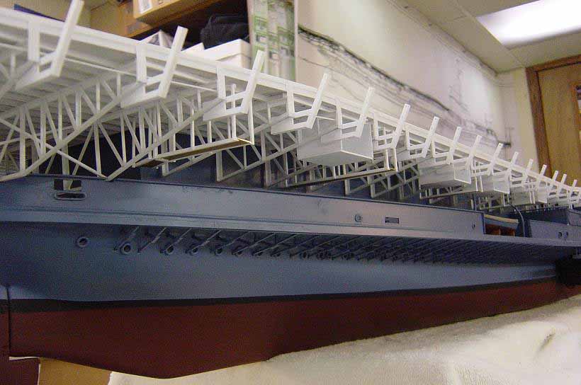
To begin the support structure, all longitudinal I-beams were added
first using 1/8 shaped styrene, using the pencil lines I added earlier
as a guide. After this was finished, it was time to build all the supporting
trusses. There are 84 of these trusses and all are pretty much the same
configuration except for their length due to the curvature of the main
deck superstructure walls, which the trusses butt against. Therefore, a
jig had to be built to speed the construction time. After measuring the
length of each truss, they are fabricated and installed one at a time,
going the entire length of the flightdeck, first starboard side, then portside.
The pencil lines previously drawn help to measure the length and align
each truss. The trusses were fabricated using styrene product again. Angle
shape and flat strip to be specific. The first few forward trusses and
the last few aft trusses run the entire width of the flightdeck, so they
were a little different from the rest. The support structure looks complicated,
but it was straightforward once I got into it. Cross bracing was added
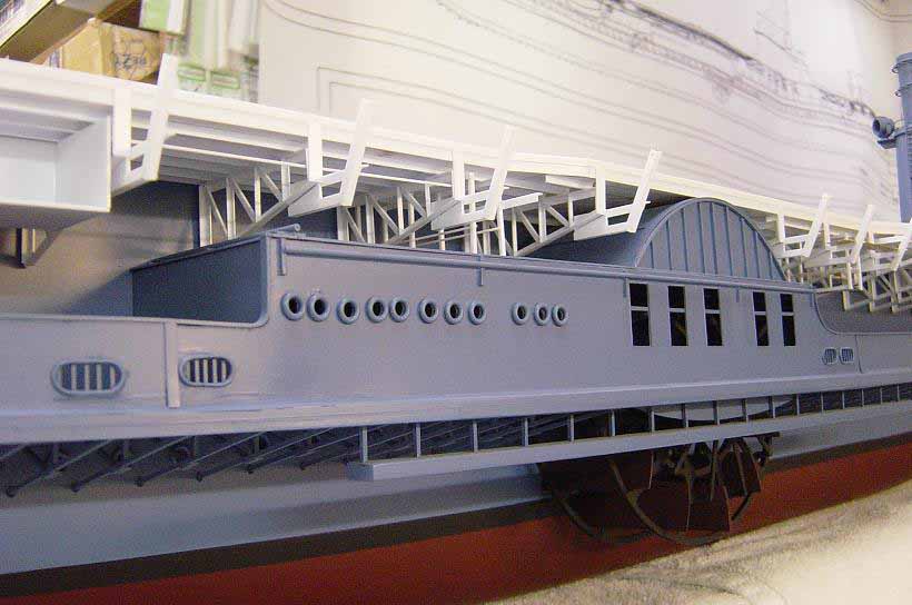
in places after all the trusses were installed. Further details were
then added including shelter pockets, blower intakes and exhausts, suspended
catwalks, etc. after which all was painted. Moving on, now that the support
structure was complete, the catwalks around the edge of the flightdeck
and other details would now be added. The catwalks are made from perforated
.020 sheet brass, cut into strips then attached. Since the supports for
the catwalks are integral with the trusses, this step went rather quickly.
Safety netting was then added, using a styrene frame and nylon mesh in
sections about 12 long each. The LSO platform was added at this time also.
Masking off areas and paint work were then done. More details will come
after the flightdeck is installed on the hull assembly.
|
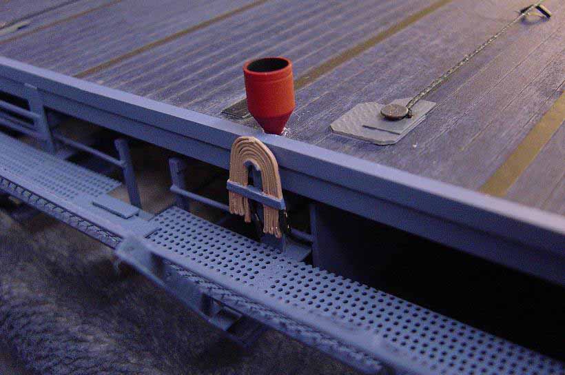
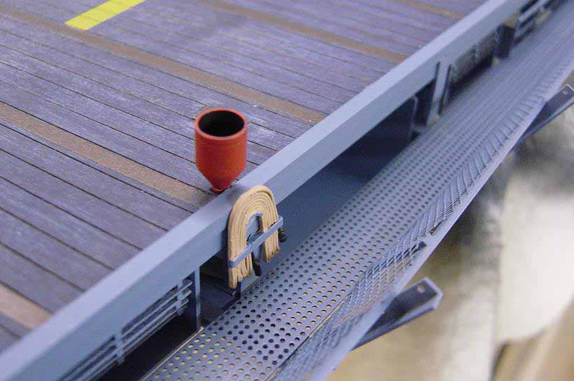
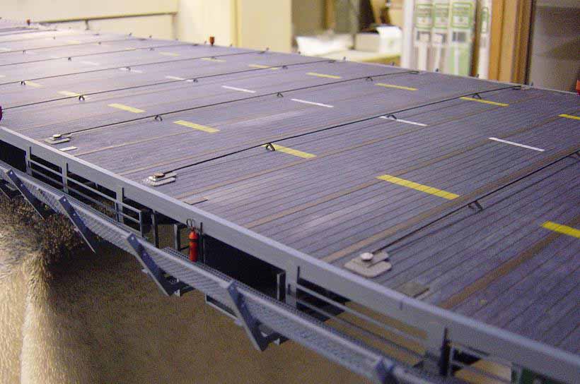
Here is a shot of one of the foam generators located around
the flightdeck. Unfortunately, they are in the wrong spot!! They actually
are placed on the catwalk, which runs around the entire length of
the flightdeck, towards the inside. I have since moved them to the correct
location. Draped fire hose is cast metal fitting from HR Products and is
in the right spot. Foam generators are made from CNC turned brass by Steve
Nuttall.
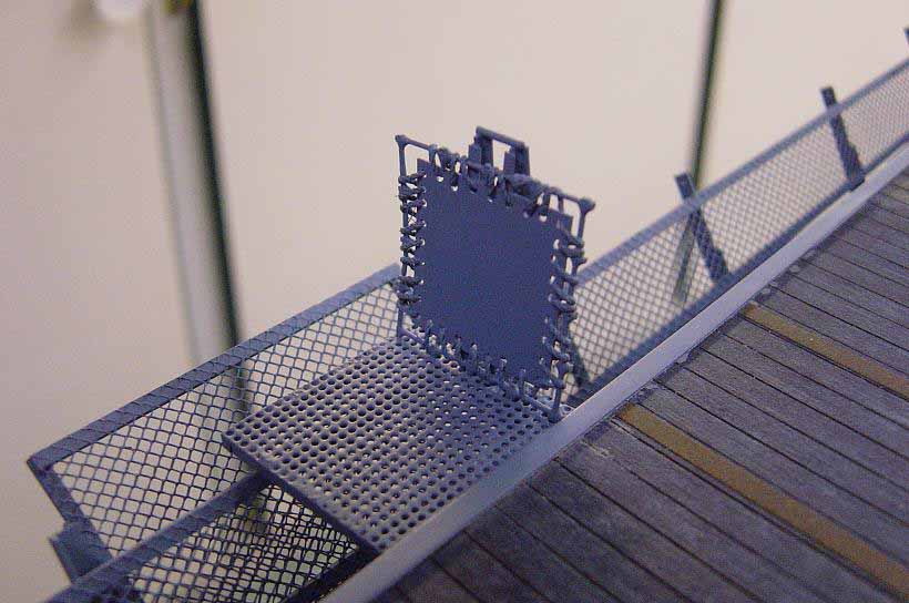
Here is the LSO platform. Platform itself is perforated brass sheet cut
to size as are all other catwalks. The windscreen is a frame made from
galvanized metal. The screen is styrene plastic which I drilled holes into
and then attached it to the frame with rigging thread. Note the safety
netting assys. here. |
|
|
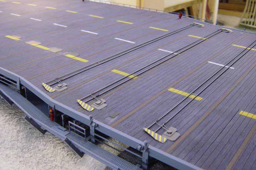
These next few shots show the addition of the arrestor
wires and barrier arms. The stations are made from sheet styrene and the
"sheave" is actually a small nail. The yielding bars are styrene strip
bent in half to support the arrestor cables which is .020 rigging line.
Note the tie down tracks are represented by 1/8" auto pinstripe tape in
a bronze color. The actual tracks are added later. I'll discuss that in
part 3. The barrier arms are made from styrene again, using strip and rod
and some small pieces of copper wire.
|
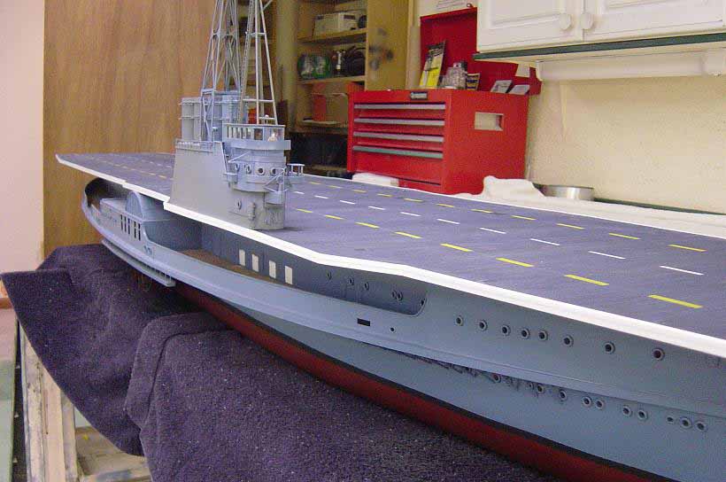
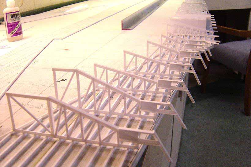
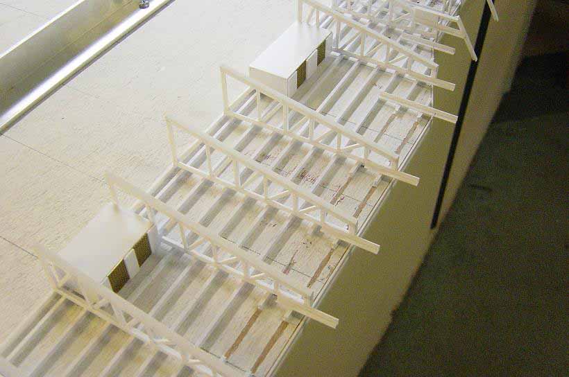
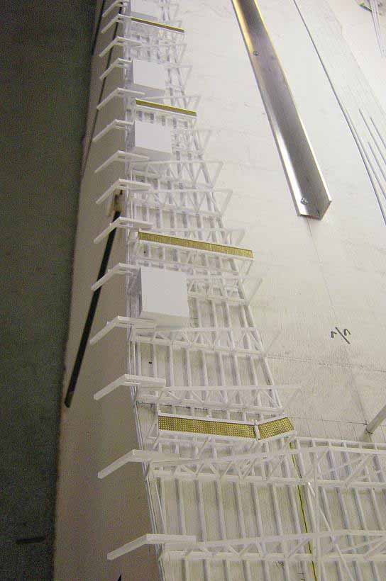
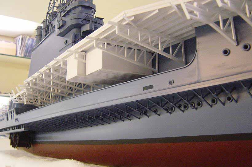
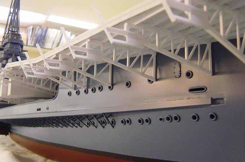
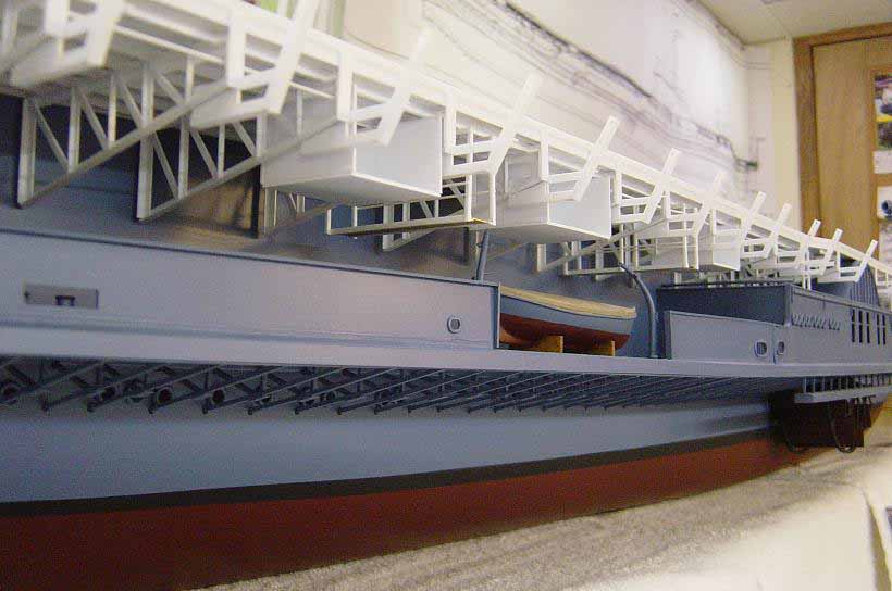
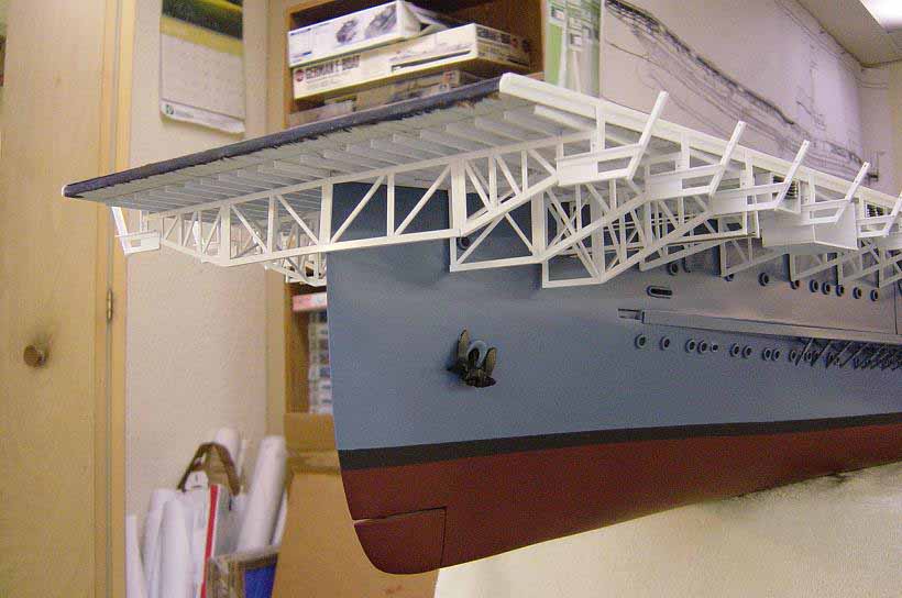
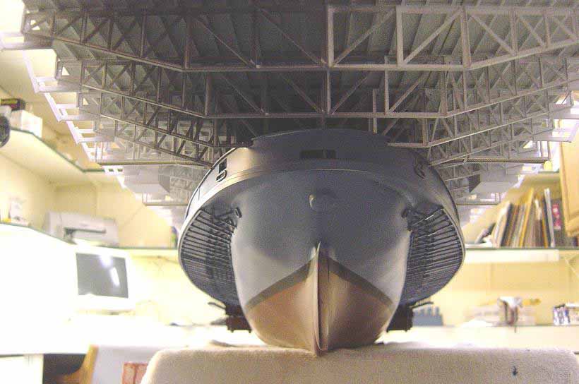
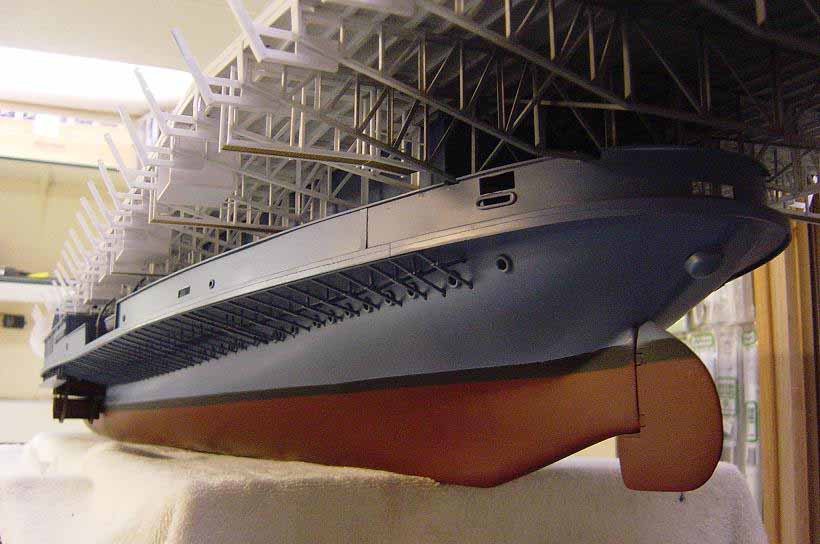
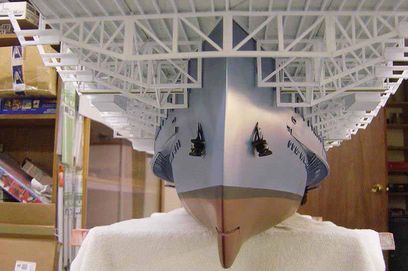
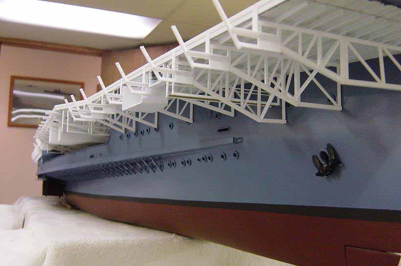
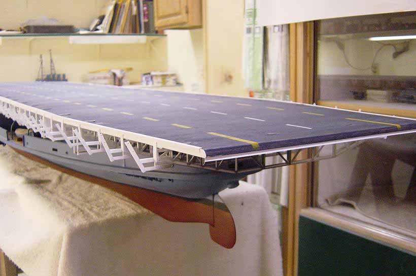
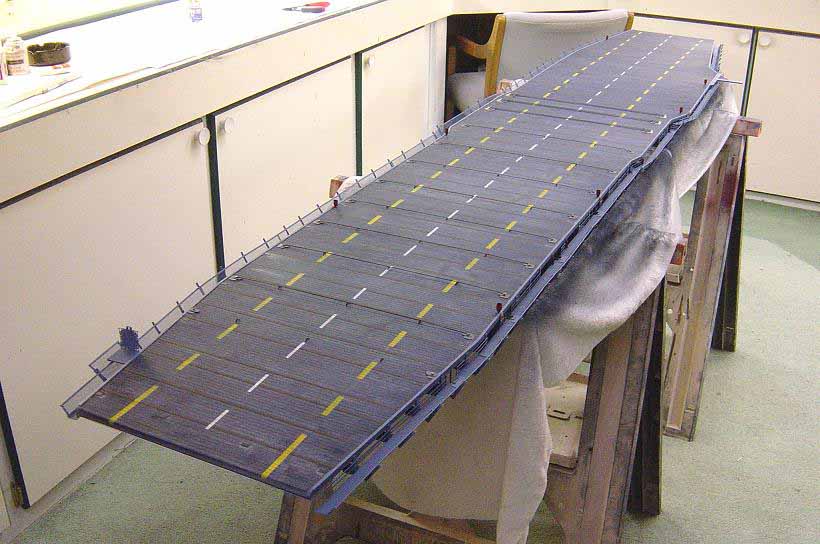
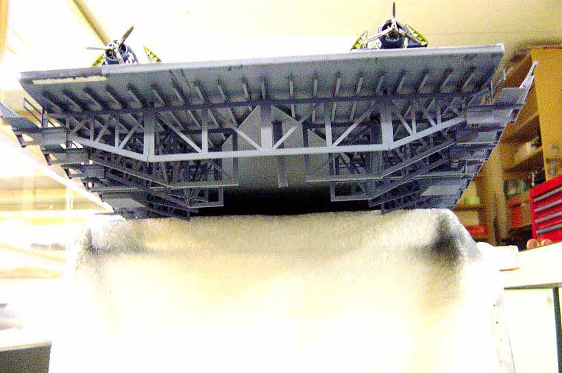
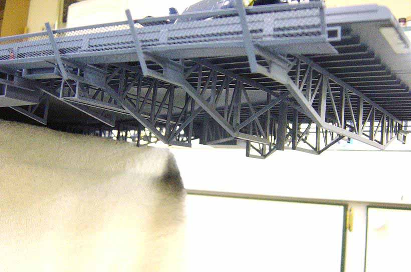
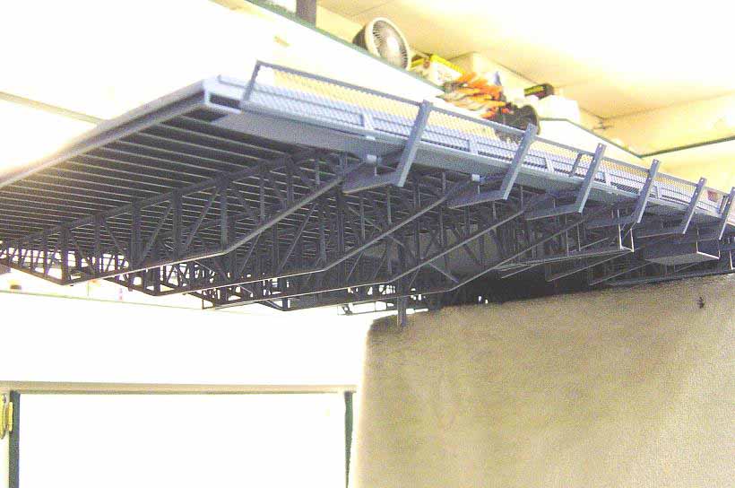
These last three photos show the support structure
pretty much completed. I'll add the very fwd. truss and the very aft truss
after the flightdeck is installed on the hull. Note the small holes drilled
into the angled outer part of the trusses. Steel cables run through here
which will be represented by rigging cord, which I'll add after the last
two trusses are installed.
|
| Well, that's it for part two. I hope I have explained things
well. In part three, I'll put it all together!! Stay Tuned!! Comments
or questions are as usual, always welcome! Till next time, "Happy Modeling"!!
Best to all, Bill Waldorf. |