U.S.S. INDIANAPOLIS (CA-35) TO
U.S.S. CHICAGO (CA-29)
By Bob Dedmon
 This
article originally appeared in the November 1997 issue of the SHOGUN, the
newsletter of the now defunct Shogun Chapter of IPMS/USA on Okinawa, Japan.
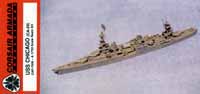
It has been updated a little in light of the beautiful Corsair
Armada kit of the Chicago in the same fit as the conversion.
There were photographs to go with the original write of this article though
Shogun could not use them, they may have been lost when Isabel took out
my model shed. RDD This
article originally appeared in the November 1997 issue of the SHOGUN, the
newsletter of the now defunct Shogun Chapter of IPMS/USA on Okinawa, Japan.
It has been updated a little in light of the beautiful Corsair
Armada kit of the Chicago in the same fit as the conversion.
There were photographs to go with the original write of this article though
Shogun could not use them, they may have been lost when Isabel took out
my model shed. RDD
The inter-war Washington and London Naval Treaties limits
produced some of the most aesthetically pleasing ships ever built.
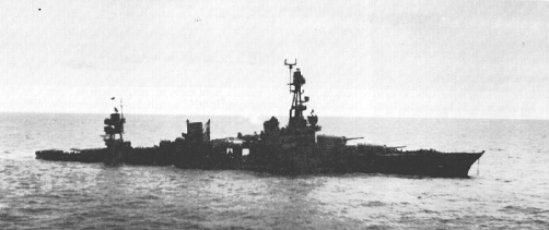
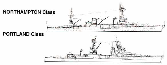
The Northampton class heavy cruisers were the second class of heavy cruiser
authorized after the Washington Treaty. The Northamptons were improved
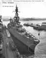
Pensacola class cruisers. Ever since I first saw a picture of the Chicago in an old naval review book of my father I have been fascinated with this ship. Before the Corsair Armadas release the choices were to either scratch build or try to convert the Matchbox kit of the U.S.S. Indianapolis (CA-35) a Portland class ship. |
|
| This is a major backdating and face-lift as the kit depicts the Indianapolis is 10 feet longer and the kit depicts the Indianapolis as it was when it was sunk in 1945. I chose to depict the Chicago just after its last yard period to the time when she was sunk at the end of January 1943. | |
 |
|
| The Chicago is 10 feet shorter than the Indianapolis between the forward superstructure and the forward funnel. In 1/700 scale ten feet is 0.17 inches. I removed this amount from different locations to maintain adequate fit in the hull and superstructure. I cut the hull just forward of the step down. The foredeck (part 1) was cut at the area where it attaches to the aft deck. The forecastle (part 7) was cut just aft of the shields for the quad 40 MM mounts moving aft toward the funnel base. The final piece that needs to be shortened is part 26, the lower superstructure. The entire aft portion behind the bevel needs to be removed. Prior to assembling the lower hull I removed the molded gun tubs on the bow, stern and the forecastle. At this point I traced and cut the decks for the mid ship 5 25 caliber anti aircraft guns (parts 6 and 23) from .015 sheet plastic. I left the tubs for the mid ship 40 MM mounts to make room for Skywaves upgrade set. I them built up the gun decks and hangars. | |
| The aft deckhouse needs serious modification. Parts
41 and 42 need to be cut down behind the fat portion of the deckhouse level
with the lower 5 gun deck then use the thinnest piece of sheet plastic
to form the deck of the aft portion of the deckhouse. I used part
28 covered with .005 sheet plastic to be the top level of the aft deckhouse
that slightly overhangs the aft main gun mount.
For the forward superstructure, first remove the molded shields on the O-3 level (part 19). At this point I used .005 sheet plastic to build all the splinter shields. All the shields measured out at 2 MM for the main shield and 3 MM for the dividers between the 5 gun mounts. At .005 the shields are easy to form to the appropriate shape. I built the superstructure, gun decks and fantail shields. I referred to American Cruisers of WW II and Cruisers of the U.S. Navy 1922 1962 to get the patterns for the gun tubs ( I have since discovered the shapes I used were incorrect per better photos elsewhere). |
 |
 |
|
|
The superstructures construction through the first three levels is according to the instructions. I used my Dremmel to thin the shields on the O-4 level. At the O-5 level I moved part 27 forward and built a new upper level from scrap plastic. I used some metal rods to build the fore mast; the aft legs are 1 long and were incorrectly mounted to the O-4 level (they should have gone to the main deck). The fore leg mounts to the top of part 27. Part 33 makes an adequate platform level for the mast (I have since learned this platform is bi-lobed around the foreleg). I made the fighting top by modifying Parts 15 and 16. I cut the director on the top of the tower them I cut the tower off flush with the remainder of the part. I then mounted the director over the resultant hole and mounted it on top of the mast poles. |
 |
| The aft mast, mounted over the aft deckhouse, is made in a similar fashion. The main supports are the same length as the legs on part 59. I used the pattern of part 28 for the lower level of the aft mast and the aft portion of part 10 for the upper level. I attached tub part 27 from the Skywave set to hold a 12 director on the aft face of the lower level. I used a .5 x .1 x .3 piece of plastic mounted at the forward (bow) end of the lower level for the spacer/riser for the upper level. I used a Mk 37 (unmodified) to represent the Mk 33 director with Mk 4 radar and four single 20 MM mounts for the upper level of the mast. The main gun houses required minor extra work. Fill in all the locator holes on top of the gun houses, install the local directors and gun barrels. I filled the gap under the barrels with sheep plastic. I needed two sets of Skywaves USN WW II parts to get all the secondary guns and other required fittings (Corsair Armada makes some very nice 5 25s they sell separately). To make my own 5 25s before the Corsair Armada set I trimmed .09 from the barrel. Chicago requires 4 each 40 MM quad mounts, one on each side of the forward superstructure and one on each side between the second and third 5 25 at the same level as the upper guns. I used Gold Metal Models photo etched 20 MM buns for the 20 guns required for Chicago. There are 2 on the bow aft of the anchor chains. There are six on the forward superstructure, 2 on the O-3 level forward of the 40 MM mounts, 2 on the platform on the foremast and 2 abreast the forward funnel. There are 2 mounts located in raised tubs side by side along the centerline in between the aft quad 40 MM tubs. There are eight mounts around the aft deckhouse, 2 on the main deck abreast the rise of the upper aft deckhouse, 8 on the lower level of the deckhouse and the last 4 are located on the top platform of the aft mast. The last two mounts are located within a common shield located on the fantail. For the tubs for the single mounts on the bow abreast the funnel and the aft deckhouse I sanded the bottom out of the Skywave tub (part 27) and cut them in half. For the tubs on the aft deckhouse I filed a hole in one side of Skywave tub (part 27). I used Skywaves part 28 for the raised tubs in between the aft quad 40 mounts. The directors for the 5 25s are Mk 33 with Mk 4 radar. Chicago had two Mk 33s one above the bridge and the other on the upper level of the aft mast. The main guns are controlled by Mk 24 director located on top of the fighting top with a Mk 3 radar located on top of the Mk 24 and on the face of the upper level of the aft deckhouse. There are optical Mk 51 directors for each of the quad 40 MM mounts, one on each side of the aft funnel located in tubs and one on the rear corner of the O-4 level. I used Gold Metal Models WW II cruiser and destroyer set for railings, the aircraft crane catapults, ladders and screw guards (Toms Model Works Northampton set would have been better if it had been available then). I used Toms Model Works early US WW II radar set for the Mk 3 and Mk 4 and the CXAM radar. The CXAM radar is located on a pole mast aft of the fighting top on the foremast. I scratch built the mast using stretched spru. The pole mast located on the aft mast is also made of stretched spru. I added a Skywave flag box to the rear of the O-3 level of the forward superstructure and two to the railings on either side of the lower level of the aft deckhouse. I used the Skywave 26 motor whaleboat and davits abreast the aft deckhouse. I then attempted to convert the kits Seahawk scouts to SOC Seagulls, using putty to extend the canopy, fabricating the upper wing out of .005 sheet plastic, and scratch forming the outer floats with Toms photo etch for scout aircraft. | |
| At the end Chicago was painted in the Measure 21 paint
scheme. I used Pit Roads ship color #13 WW II USN deck blue and
Gunze Sangyo Mr. Color #14 Navy blue. For the base I used a 12 by
4 piece of finished wood to which I applied a layer of blue artist acrylic
jell paint to represent water using a spatula to form a wave pattern representing
a ship underway (I have since taken to coating the darker blue jell with
clear blue used for aircraft lights to better represent the Pacific blue),
once it is dry I dry brush white for the white caps and foam (I overcoat
this in some areas with the clear blue for better foam color) then coat
it with clear gloss.
Would I try this project again, not likely in light of Corsair Armadas beautiful kit but Im not afraid to try it again if there is a subject I want that isnt available commercially. I was almost to this point with the Nevada/Oklahoma until I acquired one recently. |
|
| Links: | |

© ModelWarships.com