| The Iowa class battleships were arguably the best to serve
during WWII, and they had a long career after the war lasting into the
1990s. It is interesting however that the most well known (and hence most
modelled) ship of the class is not the name ship, USS Iowa, but USS Missouri.
Model manufacturers have always chosen to do Mighty Mo in WWII fit, and
when they do any of the others its usually a re-boxed Missouri. In 1:350
scale there are conversion sets available for those who wish to build Iowa,
but in 1:700 you have to scratchbuild. This is the step by step story of
my project, to convert a Missouri to Iowa in 1:700. There are significant
differences between the two ships and I will try to cover them as best
I can; hopefully there will be more 1:700 Iowas around when youre done
reading this. |
| OK then, first things first, here are the various items
I used for this project:
Tamiya 1:700 USS Missouri
GMM 1:700 US Battleships
PE
GMM 1:700 Doors, Hatches & Life rings
GMM 1:700 20mm Oerlikons and shields
WEM Colourcoats:
5-L Light Grey, 5-N Navy Blue & 20-B Deck Blue
|
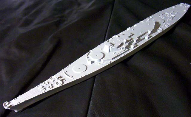
| Before gluing anything, I removed the middle deck section
from its sprue and, with a very sharp knife and significant amounts of
force removed those awful Aztec steps to be replaced with proper PE ladders
at a later stage. Also I removed the moulded-on lower bridge windows, to
be replaced by the GMM PE windows later on. Then just build the kit as
per the instructions to the stage shown on the right. |
click images
to enlarge |
 |
|
|
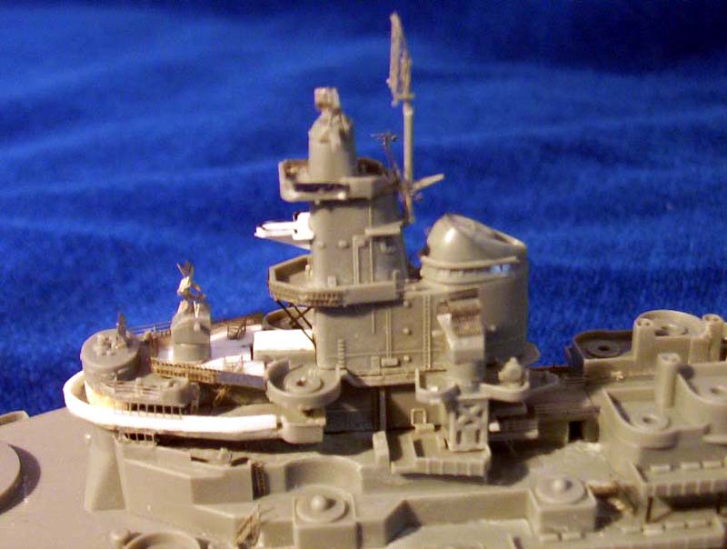
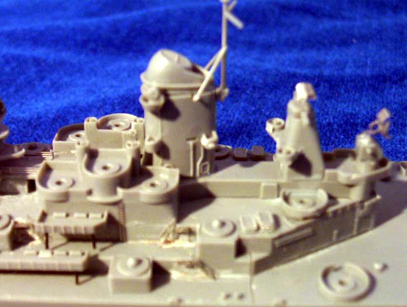
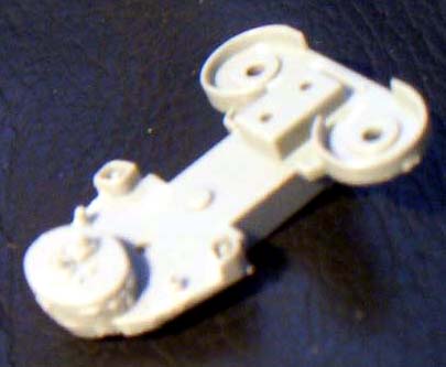
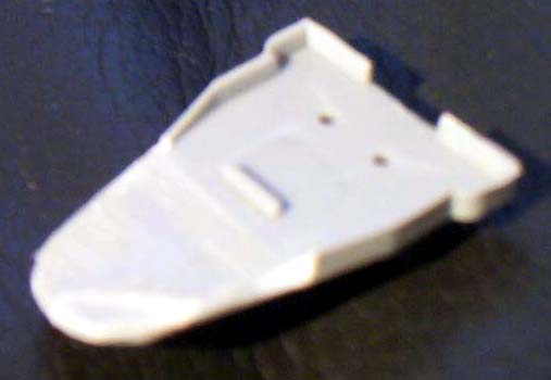
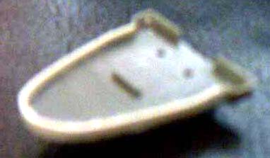
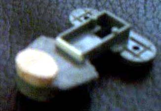
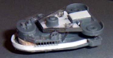
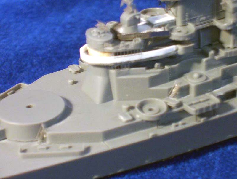
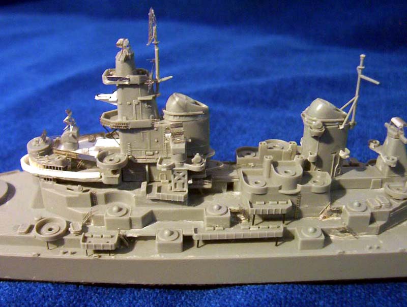
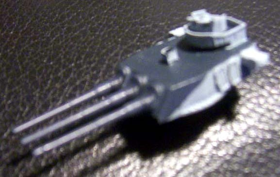
| The most notable difference between the two ships is the
construction of the bridge: Iowa had a round open bridge. Images 2-6 below
show how the kit parts were first cut and shaped correctly and completed
using styrene strips for and balsa wood to create the armoured conning
tower. After they are put together the upper bridge level (unique to Iowa)
can be built from styrene sheet and the shields added, made from the stainless
steel from the photo-etch fret. The ribbed appearance of this shield is
achieved by placing vertical ladder stock across it. Note that the support
for the forward director has been sanded to make it shorter and glued on
top of the deck level.
|
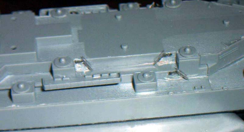
| Now back to the ladders. Where the steps have been removed I cut a
small rectangle of the stainless steel from the PE fret (very useful material)
and glued it to the superstructure so the ladder can be attached to it. |
 |
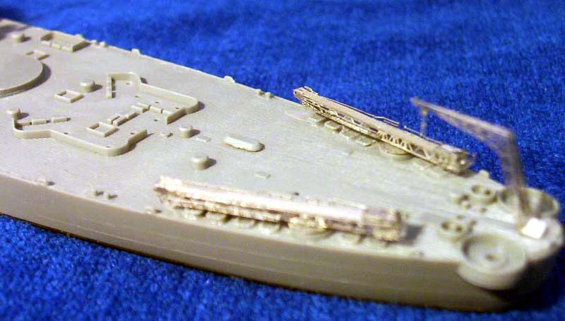
| I continued building the superstructure and adding
PE until the ship was almost complete. I used some thicker stretched sprue
to make the supports for the AA gun positions. The PE from GMM is pretty
self-explanatory. At this stage however I thought it was a good idea to
leave off the doors and hatches.
|
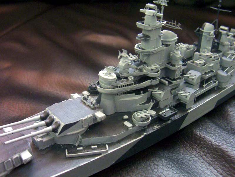
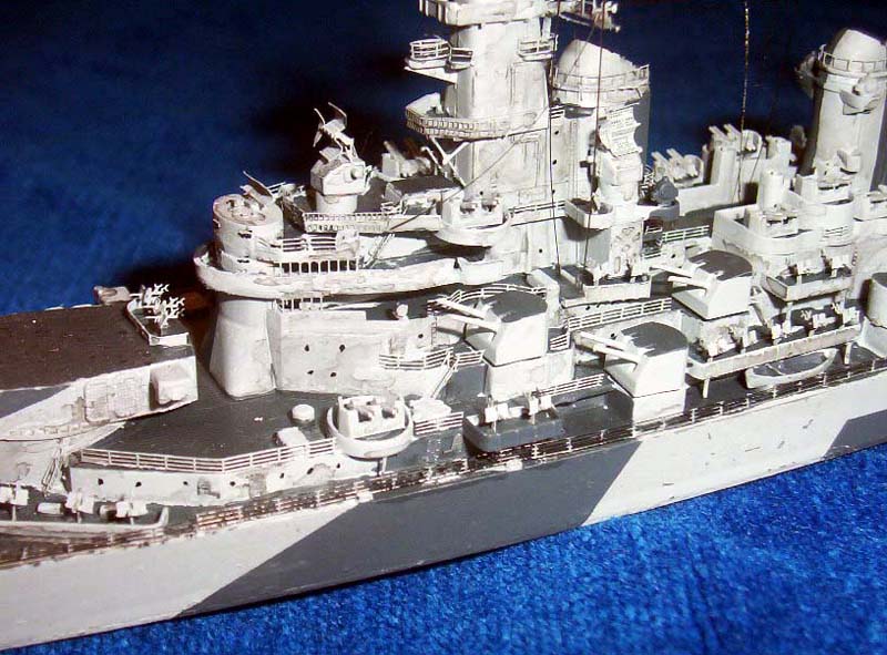
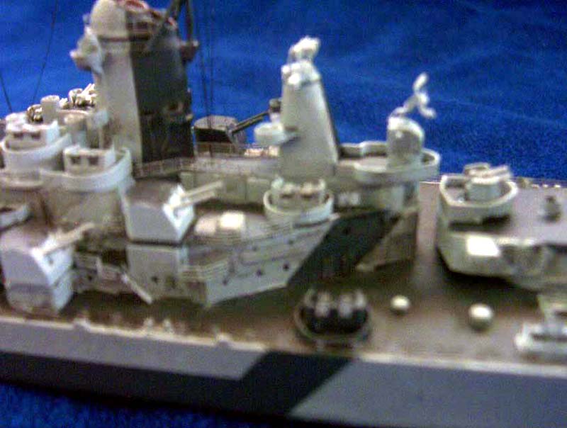
| There are a few other differences between the two ships. The forward
tower has an extra platform protruding forward at the level of the top
of the funnel, and this was made from styrene sheet. The platform below
this is supported by a simple rod structure made from stretched sprue and
it also has a ribbed appearance. For this I used the same technique as
on the additional bridge level, ladder stock placed horizontally on the
outside of the platform. |
 |
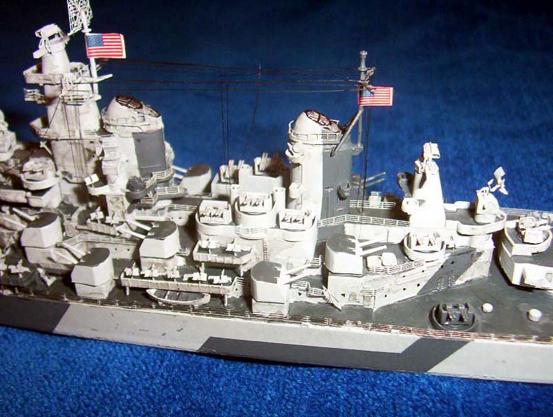
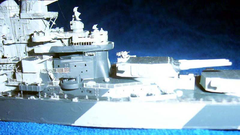
| The topmost level is almost completely rectangular so the
kit part needs to be cut down and the gaps in the sides filled with some
more small rectangles if stainless steel. Note the mast is different and
supports the square SK RADAR, not the round SK-2 carried by Missouri. Finally
note there is a 20mm gun in the tub just forward of the Mk.37 directors
abreast the funnel, so remove the stump that is supposed to be a rangefinder
in preparation for this. |
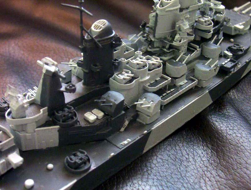
| The rear structure has other minor differences, notably in the positioning
of the rangefinder tubs. The third and uppermost tub above the three 40mm
emplacements should be deleted, as should the extra two tubs just below
the range finder position. |
 |
| The two tubs on the sides of the funnel should be separated
and placed at opposite ends pf the funnel as shown and the gap left where
they would have otherwise been fitted filled. Note that in the small tub
protruding below the three 40mm emplacements Iowa carried only two, not
three 20mm guns so remember this for when you come to attaching these. |
|
|
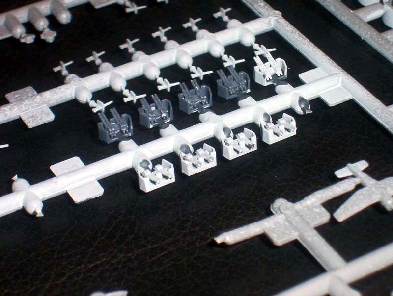
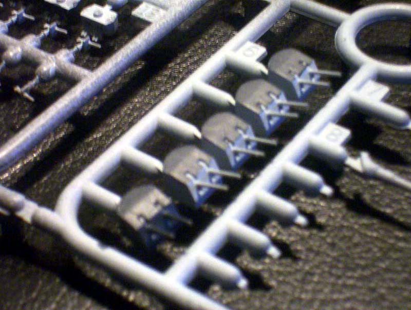
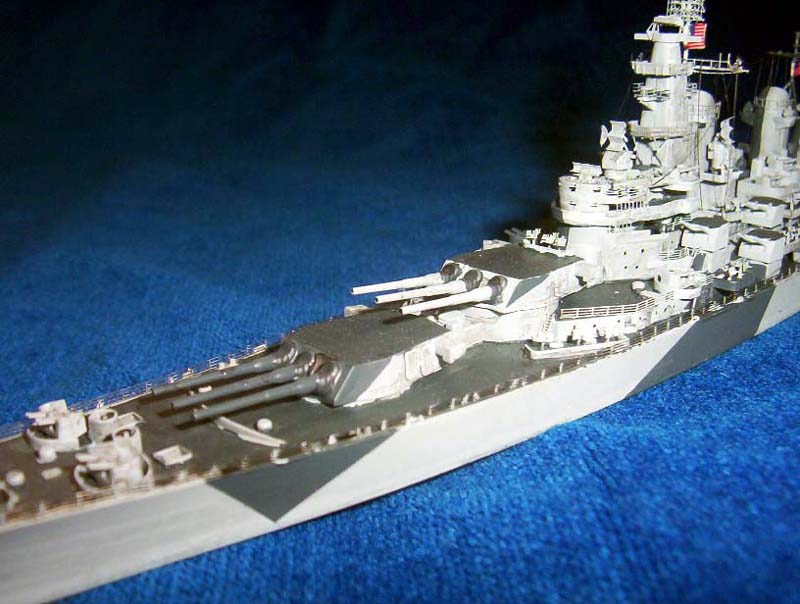
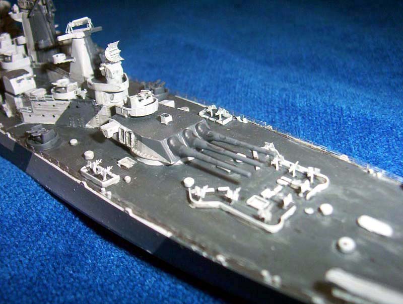
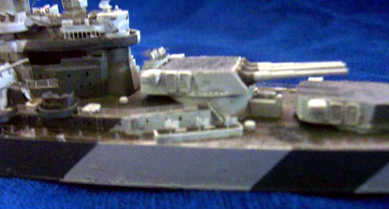
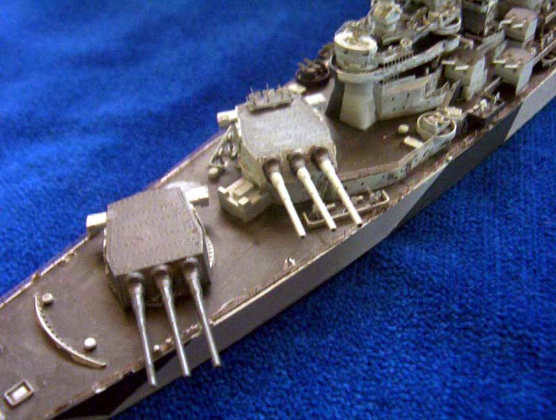
| All the armament (20mm guns not shown) was built and painted
while attached to the sprues. The only things to note are that Iowa carried
three 20mm guns on top of B turret instead of the 40mm quad mount. The
shield was made from railing but the gaps filled with paint to give a solid
shield. C turret was enhanced by adding the rangefinder tub for the 40mm
mount, made by bending a rectangle of stainless steel.
|
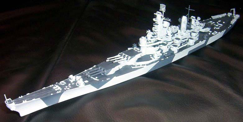
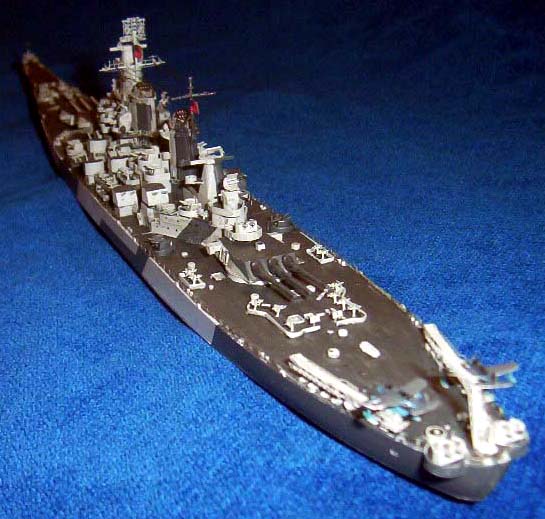
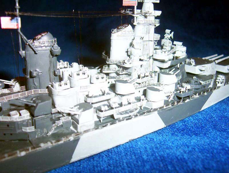
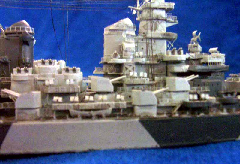
You are probably wondering by now when Im going to pain
the ship. The answer is now. I thinned some of WEMs 5-L and sprayed the
whole ship with two coats. The reason I wait until this stage ins because
it means I can paint all the major photo-etch and most of the ship in one
go rather than fiddling with subassemblies. I then masked the camouflage
and painted it 5-N and then, with a very small brush and very carefully,
I painted the decks 20-B by hand. See images 18-22 below for the ship at
this stage. Note the 40mm guns have been attached, but the 5 and 16 guns
are just sitting there to make the photo look good. I will only glue these
on after I have finished other details.
|
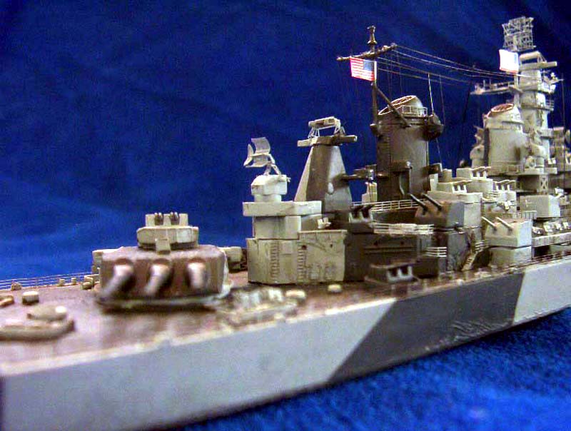
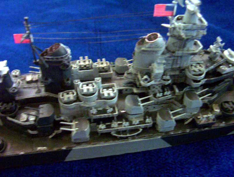
| For the final detailing I painted and weathered the PE
doors and fire hose racks separately then attach them to the ship. The
same goes for the 20mm guns. I used watercolour washes to weather the ship
slightly as well as a pencil to lightly highlight detail or create smudges
and traces of water on the hull. And now for the railings. The main deck
railings were attached to the ship unpainted. Again I used a small brush
to pick out the stanchions in the relevant camouflage colour and then used
my black permanent marker to ill in the horizontal bars. I do this because
it keeps them thin and gives the correct impression that the railings are
cables through stanchions, not solid bars. The upper railings however were
all painted 5-L before being cut to the correct length and attached to
their correct positions on the ship. |
|
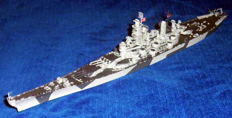
Finally, the flag decals from the kit can be attached and the rigging made
from stretched sprue. A little dilemma was how to convert the 63 decal
to read 61. I hit on the idea of attaching it to the ship then, once
again using my trusty small brush, paint the horizontal portions of the
3 in the background colour leaving only the vertical part which resembles
a 1. |
|
I hope that was a useful article for you, especially if you wish to try
a conversion yourself. If you have any queries you can contact
me via the
forum
on this website. |