 |
|
|
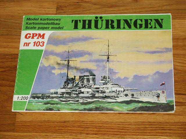
A little history about myself:Im an average modeler and have been building models for 25 years now. After building most of the Nichimo 1/200 scale kits over the last 15 or so years I have been always looking for more 1/200 kits. With the exception of the Trumpeter 1/200 modern Chinese destroyers I have been without much hope until I stumbled on the suddenly popular paper models. I found these first on E-Bay. I visited a few web sites, the best of which Sauls page http://www.cardmodelers.org, to educate myself on these models and techniques. The best advice I got was to start slow and work up, destroyers then larger. I have built several models and have decided to write this page with GPMs SMS Thüringen as my first challenge. |
click images
to enlarge |
||||||||||||||||
 |
|||||||||||||||||
The Ship:SMS Thuringen is one of 4 ship class that was Germanys second post Dreadnaught. She was equipped with 6 -12 inch twin turrets arranged in a standard early 1 fore, 1 aft, and 2 side by side mounts. The ship as typical with WWI vessels also had an array of useless weapons such as 6 casemate guns and torpedo tubes, 1 bow mounted, 1 stern, and 1 each port and starboard, all below the waterline. |
 |
||||||||||||||||
General:Most paper models come with white glue tabs on the subassembly components. In most cases I simply cut these off completely and when I need to have a tab I make my own from light card stock and glue to the backside of the parts. This is especially helpful in creating smooth transitions when two pieces are butted up to each other. It also helps to make truer square corners when folding polygons. For large flat deck or superstructure surfaces I usually add folded 90 degree straight edge cardboard or even good square balsa stock to stiffen and maintain flat surfaces that other wise may become concave. |
 |
||||||||||||||||
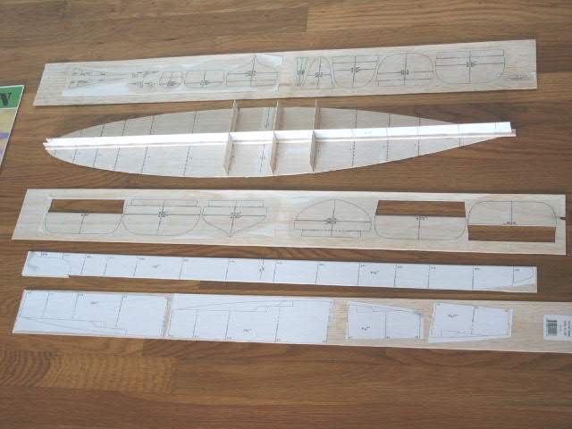
The Model: Part 1 (Hull Construction)Framing:This model like most others is written entirely in Polish. The figures are actually pretty good on this kit and generally construction is in numerical order. No real shortcuts are advisable but over time with experience the process comes pretty easy and you will develop your own techniques. This model is the second that I have tried without using cardstock as my primary lamination material, NOTE when you laminate the deck be sure to account for the height of the upper hull side 6 gun windows these must fit to the deck while allowing the case mate gun wells to fit the hull sides. I got lucky. I got tired of fighting white glue with the thin paper patterns. The paper stretches when it gets wet and doesnt always give you an accurate pattern after lamination. The kits generally come with thicker card for the printed components and these hold up much better with white glue. |
 |
||||||||||||||||
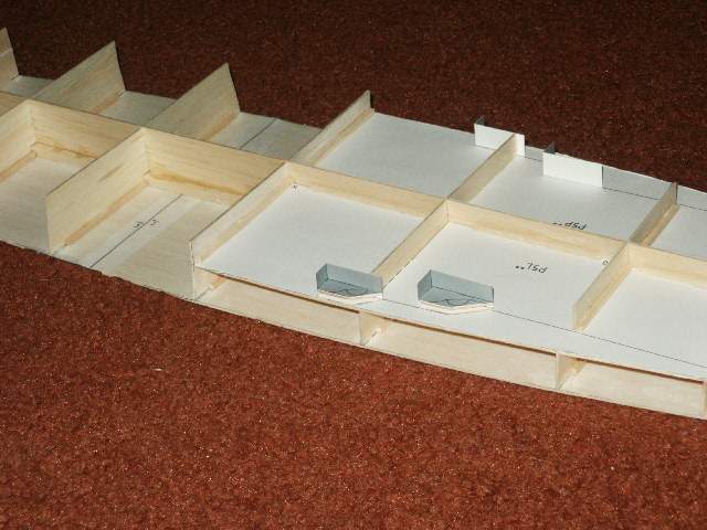
| The model is a standard build paper model. First step is to build the egg crate hull. Start by laminating the paper keel, bulkheads and water line deck onto either cardboard or balsa. I chose balsa 1/32 thick, the kit is designed for 1 mm. Most of the older kits rely on thinner 1 mm lamination, the printing is based on this. The newer larger models are as thick as 2 to 3 mm. You can use any size you want provided you account for it when cutting out the parts. I chose balsa and use CA to laminate because cardboard and white glue generally warp more. My previous kits are all cardboard and the results were good but balsa is much easier to cut. Connect the keel and deck patterns prior to lamination and then laminate onto a single sheet of balsa or cardstock. | |||||||||||||||||
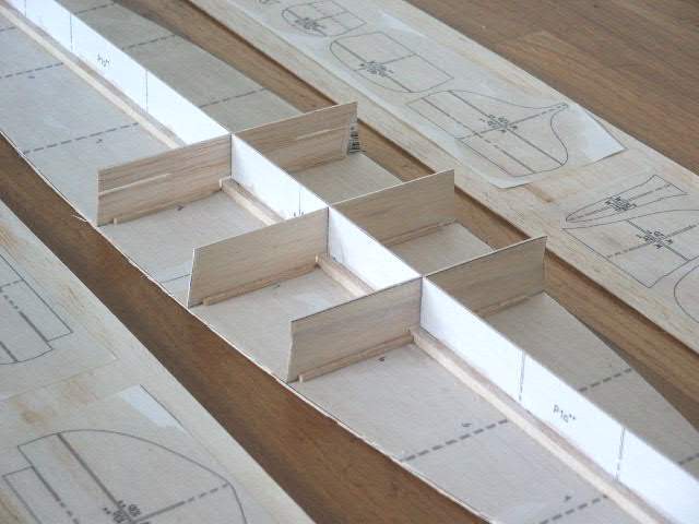
| Since the water line deck is very flat after lamination there was no reason to glue it down to the glass construction plate. Next I glued a 3/32 square balsa rail on the deck aligned to the keel, placed the keel in position, then added another rail on the opposite side. I used slow drying CA for this and firmly held the keel down. The result was a truly flat keel. Cut the horizontal slots in the bulkheads W3-W5 and W8-W12. I dont slot the keel and bulkheads although most people do. Next place all of the upper bulkheads in position and firmly hold in place. The hull was flat and actually pulled a slight suction when trying to lift it straight up from my table. Next glue P4, P5, and P7 in place. Use the slots and align the plates. Dont glue until both opposite sides are installed, this will help keep you from bending the frame. Glue P4 and P5 in place. I added 1/8 square balsa rails by running a bead of CA then setting the rails against the corner. Do not force the issue, the parts will hold no problem. Glue P7 in place at the stern, this is a visible deck when the model is complete. | |||||||||||||||||
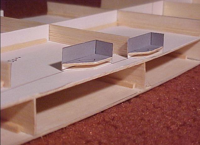
| Next assemble the 6 casemate recess assemblies 27 29 and install onto the decking plates P4 and P5. Note in polish P means right and L means left. Make sure the upper edges of these parts align to the upper edges of the bulkheads, I had to trim one P29 on the port side aft by snipping with small scissors. | |||||||||||||||||
| I laminated the main deck onto heavy card stock using Elmers spray non-acidic adhesive. Install the main deck onto the frame. If you want a waterline model at this point move onto the plating the hull sides. | 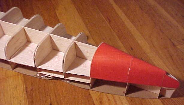 |
||||||||||||||||
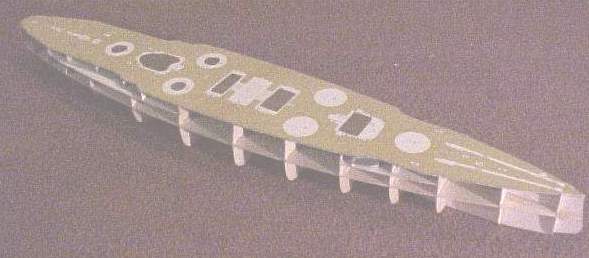
| Install the lower keel and hull formers. At this point I added balsa to the lower hull formers to allow a slight mismatch while installing the lower hull plating. Sand the entire assembly using fine paper to ensure a smooth transition for the plating. I used a heavy black marker to outline the hull formers prior to installing the added balsa to prevent sanding the formers too deeply. | 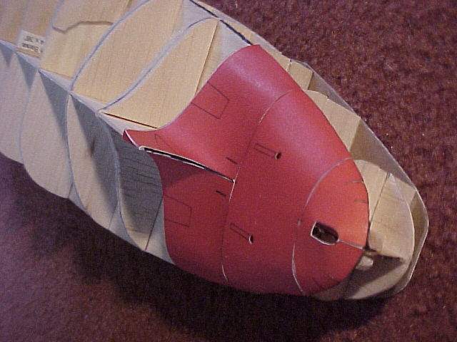 |
||||||||||||||||
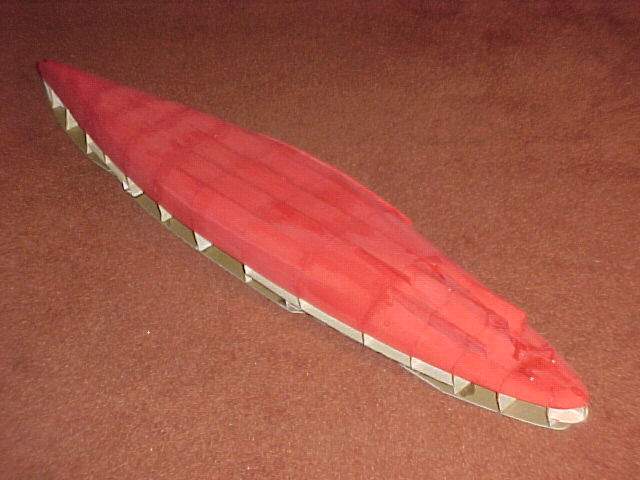
Plating the Lower Hull:The hull plating is well fitting. I prefer to start with the bow and stern and work towards the center. If there is any mismatch it is easier to repair the center of the hull than either the bow or stern. This ship is equipped with a bow mounted torpedo tube and the first section is in 3 pieces. The fit is the best of any kit I have built to this point. The model is also equipped with thin seam strips to cover any misaligned joints. Build the entire hull bottom then frame the propeller shaft conduits. Install everything but the propeller blades and rudders, these should wait until after the entire hull construction is finished otherwise you can be sure they will be broken off as a result of handling. To pre-form the plates prior to installation I rolled my razor knife gently inside the bends with the parts laying on the carpeting in the house. This simplifies the installation and put less stress on the glue joint allowing it to dry without having to hold it in place. After finishing the hull bottom I painted the entire outer skin with Testers basic flat red enamel. |
 |
||||||||||||||||
Plating the Upper Hull:This model presents a set of challenges not typical of models of post WW1 ships because of the casemate guns. With this model the case mate gun positions have to be assembled onto the insides of the hull sides prior to installing the hull sides onto the frame. Also at this point and on I paint the cut and folded edges of all of the parts installed to cover all of the unsightly white seams that would otherwise be present. (These models are noted for not requiring paint, but in reality the edge painting is very tedious and time consuming) Upper hull plating is best done by working from the bow to the stern and alternating form side to side until you reach the stern. I also like to punch out all of the port holes using a punch die set to improve the look of the kit. Because of the inner frame the holes will be black and no backing is needed. |
 |
||||||||||||||||
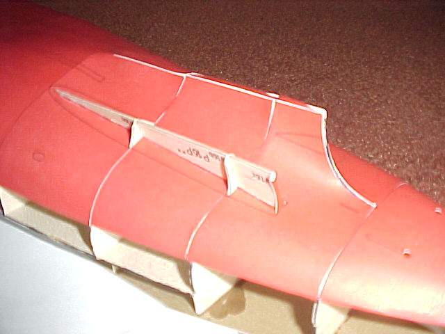
| I started by preparing the upper bow plates item 32b by punching out the port holes, and painting the cut edges. I also painted the ships shields red to match the artwork on the cover page, Im not sure this is absolutely correct but it looks good. Next align the plates 32b onto the hole and mark the hull former locations on the white skirt of the lower edge. Trim the skirt around these marks. Construct the 4 gun casemate wells 24a and install on the backside of the bow plates 32b. Install gluing tabs on 32b at the aft edge to provide backing for 32c. Install the assembled upper bow plates to the hull. Alignment was pretty good. Install 32c, pre-bend the porting of 32c to fit the forward most 6 gun well. Assemble 32a by installing the case well 30 onto the back side and add glue tabs to the aft edge of 32a to provide backing for 32d. Next prepare the hull sides 32d by adding the 6 gun wells and tabs and install onto the ship. Prepare 32f by punching out the port holes and painting the trim. Prepare 32e by adding 30e gun wells and gluing 32f onto 32e. Install these onto the aft portion of the hull, on my model the two 32fs came up about 2 mm short of each other at the stern, I added a piece of thin copier paper and painted to match, the results are acceptable as it just looks like a piece of added plating and youll be the only one to notice. In this case instead of trimming the edge on 32f like 32b I trimmed the hull formers W12-W14 to allow the edge of 32f to fit cleanly. Install 32g and 32h, note there is a door to added to 32g, this does not appear on the plans but the part is printed right next to 32g. It gives a nice 3-D appearance to the door. Install the stern plate. Now install the deck surfaces 25 and 26. I had to trim mine a little to get them to fit. Install the added armor plates 32j to the stern. I now added the small deck supports angle brackets to the 6 gun wells. I chose to do this after plating the hull but it can be done at any time. The parts 30c 30f are designed to be folded back on them selves to get color on both sides. I simply painted the back side of the page prior to cutting them out and did not fold. These parts are too small relative to the thickness of the card stock to get a good fold. Next step is to install the hull side runners 33. I replaced these with 1/16 balsa stacked to 1/8 x 1/16. These are out of scale but do to the non perfect hull form the balsa is much easier to form and the part looks much better without gaps between the hull side and the inner edge of 33. With the seemingly zillion underside braces installed the finished product is still impressive. | |||||||||||||||||
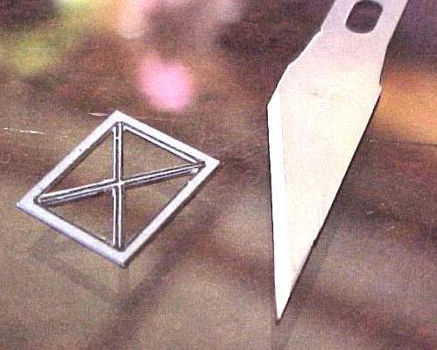
Rudders:I replaced the paper parts 19b and 19c with styrene rod. Using the Waldron Punch/Die I punched out the holes in 19d and 19e prior to cutting them from the sheet. The construction is very simple and the results are eye appealing. |
 |
||||||||||||||||
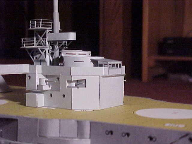
Superstructure:The ships superstructure is separated in 3 very defined sections, the bridge, the funnels and the aft deck house. I decided to build from the center out to help reduce handling problems. |
|
||||||||||||||||
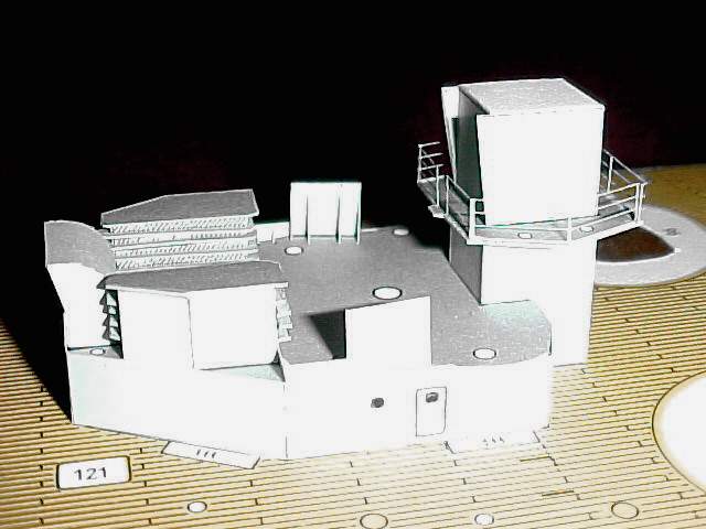
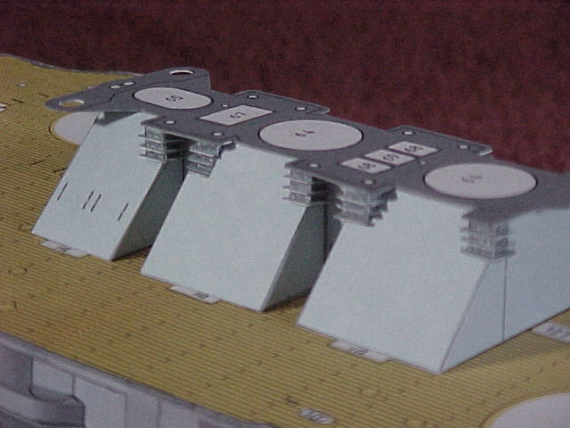
Funnel Base:The funnel base parts 55 57 are excellently designed and fit the deck perfectly, I used the drawn on tabs for these 3 parts. Start in order with 55, attach to the deck. Install the first set of 58s but in the case of these parts remove the fold tabs and add an internal tab, otherwise 56 will be too far aft. Install 56, then another set of 58s and finally 58. Cut out both halves of the deck 59 and laminate. To ensure a good fit with the 59s edges only cut out the outer most rectangle then after the laminating finish the edge cuts and paint. Next assemble the small vents 60 63. Install the laminated deck 59. |
|
||||||||||||||||
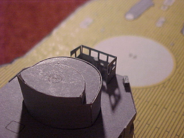
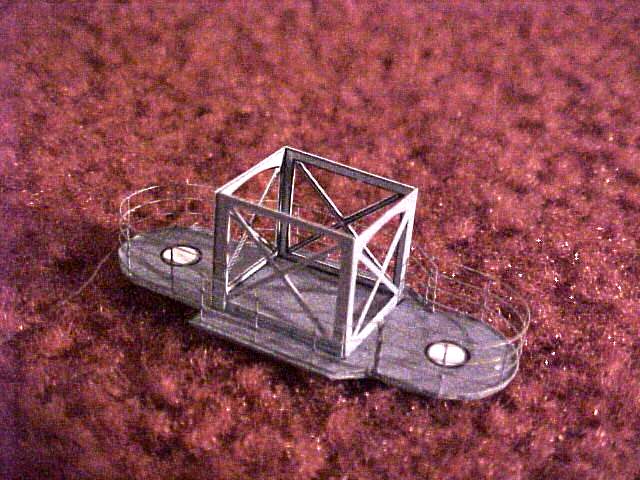
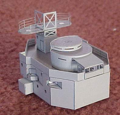
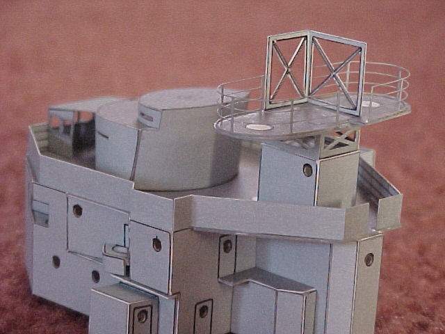
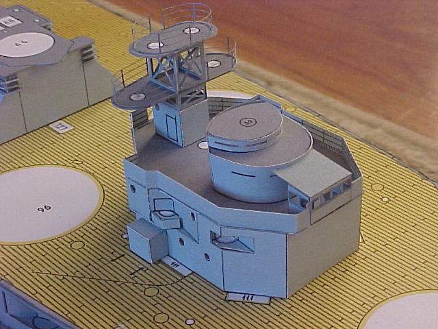
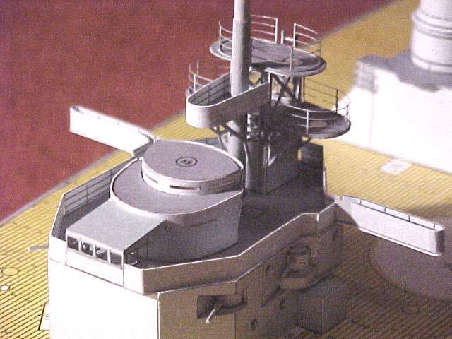
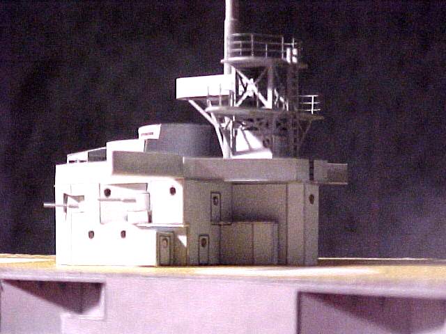
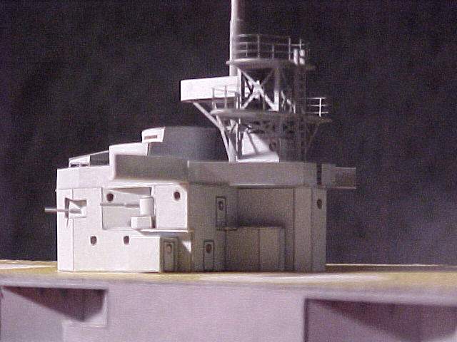
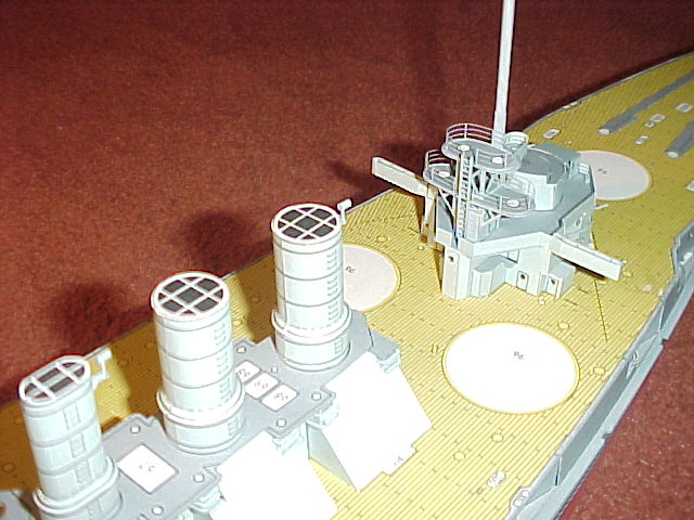
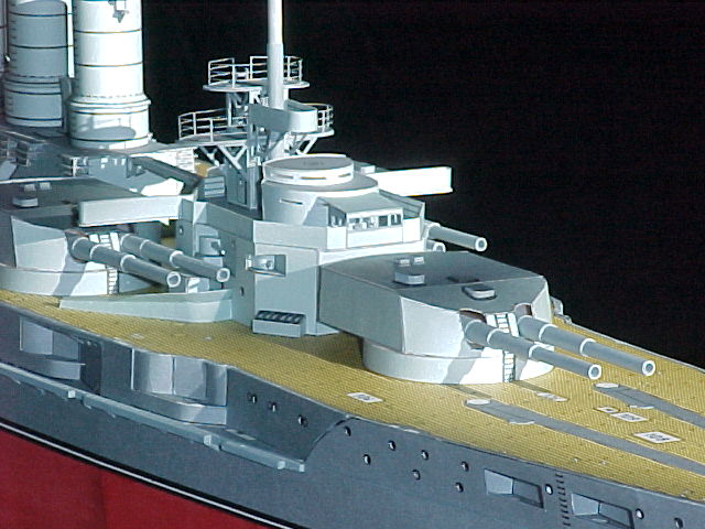
Bridge Assembly:Laminate or add edge blocks to the surface of the base 34a to provide a good gluing surface for the bridge sides. Cut out and fold 34e. Do not install 34e onto 34a yet. I added corner balsa blocks to the upper aft portion of 34e to reinforce it while inserting 34g. This will become clear when you fold the gun well form on 34e and try to hold it while assembling the bridge. I added a horizontal brace to maintain the proper width of 34e while installing 34g. Attach 34e onto 34a, I glued 34a to a glass surface to be sure it stayed flat while 34e was drying. Assemble the 2 gun wells 34f and insert into 34e. Laminate 34c and 34d to 34b. I added a brace to the underside of 34b to keep it from bowing, then install 34b onto 34e. I typically brace all of the large horizontal flat surfaces as these parts have a tendency to sag. I also add material internal to most superstructure parts with port holes to prevent seeing completely through the assembly. Install 35 37. Assemble the armored bridge 38 and install onto 34b. I removed the thin blackened window lines to improve the window effect of the armored citadel. Assemble or replace with other materials all of the bridge equipment 40 and 42. These need to be installed before the deck house 41. I removed the deck house windows on 41 prior to cutting the deckhouse from the sheet. Cut the entire deckhouse 42 from the sheet as one piece but do not scribe the fold lines. After removing 41 from the sheet I used a standard single edge razor to cut all the fold lines, do not drag the blade, simple push straight down, the material on the edge of the outer windows is extremely thin and will not fold and will likely tare if you use the #11 blade to cut them. Glue the front of the bridge, the sides, and then paint. Glue the bridge roof and the final appearance is well worth the extra effort. I added the paper rails to the bridge top but installed them with the printed lines inside and the solid face outside. Note the instruction book does not show the installation of the port and starboard flying bridge wings. These are provided in the kit including the rails. Do not install these until the end of the bridge construction. I accidentally did not leave a gap in the bridge rails but was able to cut the slot with a single edge blade just before installing the wings. Assemble the radio room 43 and install on the bridge. Cut out the lattice support structures for the lower search light platform 44. Install these onto the radio room. I added photo rails to the laminated platform 44 then installed it onto the lattice structure. Apply the underside supports for the platform 44. I did not laminate the platform supports but simply painted the backside of the paper before cutting them out. Build the upper searchlight platform 45 46 in the same manner. Note that the actual ship photos show no outer canvas covering for the handrails of either of the searchlight platforms. Install the forward platform 47 but with solid rails like the bridge. The trickiest part of the bridge to this is this platform and the 2 underside supports it sits on. Be sure to punch out the main mast hole on 47 prior to installing it on the model. The next step is to erect the main mast. I used solid styrene rod for this with the exception of the lower portion. To achieve the telescopic look simply roll copier paper around the lower portion. All of the lengths are measured from the parts and the upper mast pole layouts included in the kit. I used the paper parts 48d and 49. next step was installation of the 4 casemate guns built into the bridge. After punching the barrel holes in 34h and 52 install them onto the bridge. The fit is pretty good. I made the barrels by rolling .040 styrene rod with thin copy paper to simulate the barrel recoil telescope. The final appearance is excellent. Install the barrels into the holes and position them as you like. At this point I added the 2 wings and then finally glued the bridge assembly onto the main deck. Install the swell breaks 54 onto the deck. All the remaining small details will be added at the end of construction. I installed an N-Scale model R/R ladder on the back of the searchlight platform (scale 1/160). |
|
||||||||||||||||
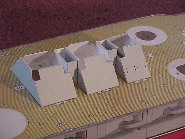
| Aft Deck House: Unfortunately my cameras disk was corrupted and when I went to download the images onto the computer I was unable to use the data. The aft deckhouse construction is actually no different than the bridge anyway. The aft deck house search light platforms are virtually identical to the main bridge platform. There is no structure built around the aft mast so I waited until the end to install it also dont install the platform 87 at this point, it is too frail and wont survive handling. | |
||||||||||||||||
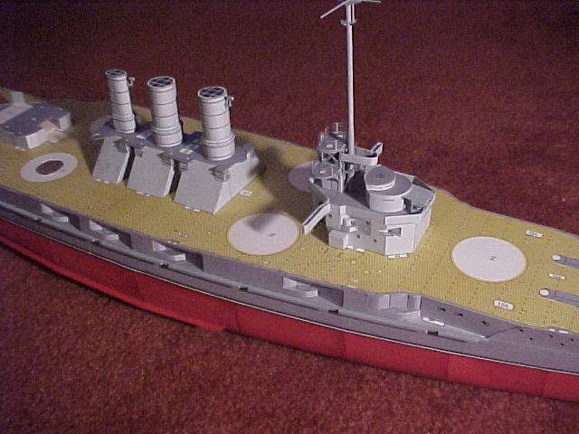
Funnels:The funnels are extremely simple in this kit, the only non-kit work I did was to laminate the upper and lower bases for each funnel with balsa to provide a good gluing surface. The 2 fore funnels are identical and are basic cylinders. The aft funnel is oval in shape but is also very simple. The look is excellent when done. Each funnel has a conical skirt, these parts I preformed using a screw driver. The seem is a but joint the I united them with a thin piece of copier paper added to the back side. The skirts were then simple dragged over the funnel tops and slid into position. After locating them I applied a light amount of white glue with a brush then painted off the excess with a wet brush. At this time I added the funnels to the base. |
|
||||||||||||||||
Main Turrets:Now for the business end of this model. I have made turrets in the past with solid barrels of both wood and styrene but after building the USS Portland turrets I will mostly just roll the paper barrels as supplied in the kit for all guns 5 scale inches or larger. See the Matsu 5 barrels and the Portland 8 barrels. Very tightly roll all 12 barrels 96k. I rolled each over a thin wood dowel then manually rolled each 2 to 3 times. Each time the barrel got progressively thinner unit I got to a visually good diameter. Surprisingly this method will yield pretty consistent barrels. After tightly wounding each barrel I painted about a quarter inch of glue on the last portion of the largest diameter and firmly held for a couple minutes. Now the barrel is held with a small flare on each of the telescoping smaller diameters. I applied glue to each one individually while holding tightly from the largest to the smallest until I got to the last, longest, diameter the end of the barrel. I applied glue here as before but as I held the barrel I inserted my jeweler screw driver to support the ID while the firmly holding the barrel between my fingers and thumb. This worked remarkable well. Make all six turret bases and install on the deck. Be sure to point the ladders in the proper direction, the ladders go between the barrels. These are simple structures like the funnels. Laminate the turret bases 96c. Cut out 96g and roll the face then glue to 96c. Install the back plate 96h. At this point I waived slightly from the kit. Install a small wood dowel on the backside of each gun barrel. I installed a solid balsa block in lieu of 96d and 96e. Use CA glue and glue the gun barrel dowels on top of the block. |
|
||||||||||||||||
Superstructure and Deck Work:Complete the remaining detail work for the superstructure and main deck. This part of the project takes easily the most time and is a little tedious after awhile. The small deck vent covers I built by cutting them completely and then building them each like a erecting a card house. The search lights are excellent. I repaint them black after assembly to hide the white cutting edges. The cranes were built entirely from the kit paper except I wrapped the main poles over solid styrene rod and I used .010 and .020 styrene rod for the cables. I then painted the entire assembly. I replaced all of the chocks with styrene rod. The anchors are made entirely from the kit paper and look nice. I used cheap jewelry for the anchor chains. |
|
||||||||||||||||
Life Boats and Launches:The life boats and launches are basically small ship models in there own. It has taken me a few models to get decent ships boats, these are marginally acceptable but they are better and every time I make some they seem to get a little better every time. |
|
||||||||||||||||
Anti-Torpedo Netting:I used screen door replacement screen rolled tightly to make the torpedo netting and styrene rod to make the poles. The netting was left black because it doesnt paint well and roll. If you paint it after rolling then the netting tends to clog and the result isnt very good. Besides the black stands out nicely. |
|
||||||||||||||||
6 Casemate Guns:I made the 6 gun barrels by rolling thin copy paper over .060 styrene rod. This looks excellent when done. I used the following formula right or wrong to size my barrel ODs. Gun bore + 2(75% bore). (3+ 2(.75(6))/200=.060. I plated over the 4 small 4 guns near the bow, the ship may be built either with the gun bays open with the guns visible or closed as they were very wet when under way. |
|
||||||||||||||||
Propellers:Next assemble and install the props. I make my own shaft ends by turning down wooden dowels then glue the paper blades. |
|
||||||||||||||||
Rails:I finished the rail installation, using Toms. I will have to learn how to make my own photo etch or even paper rails because as nice as these are they are too expensive over time and I plan to build these models for years to come. I have seen the models displayed by GPM on their site, the Lützow for example, where they clearly have paper rails. By the way I have the Lützow and cant wait to build it. |
|
||||||||||||||||
Finally:This model is fairly middle of the road complex by todays standards for new models. I again highly recommend building a few destroyers first and even at that to start with an older simpler kit. The old Maly Modelartz kits are great starters and look pretty good. None of the new kits that are released I would consider anything other than difficult as it seems every one is trying to outdo the others with detail. Most of the smallest parts are really too small for NORMAL people to build but are easily replaced with other materials. |
|
||||||||||||||||
| My ultimate goal is to build my all time favorite battleship the IJN Nagato. This kit ran me 49.99 on ebay and will need only minor improvements. It is manufactured (printed) by FLY and like all FLY should go together pretty well. GPM I believe owns the FLY copyrights so who knows they may reengineer it. Nagato has always been my favorite, worlds first 16 gunned battleship, far outclassed all US ships until the 30s when the Washington class was built. She was fast for her day, mean and tough. Survived countless US air attacks before being sunk after 2nd A-Bomb drop at Bikini Atoll. | |
||||||||||||||||
|
|||||||||||||||||

© ModelWarships.com