Reviewed by Timothy Dike
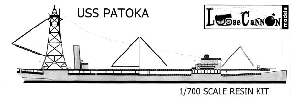
| USS Patoka (AO-9, later AV-6 and AG-125),
1919-1946
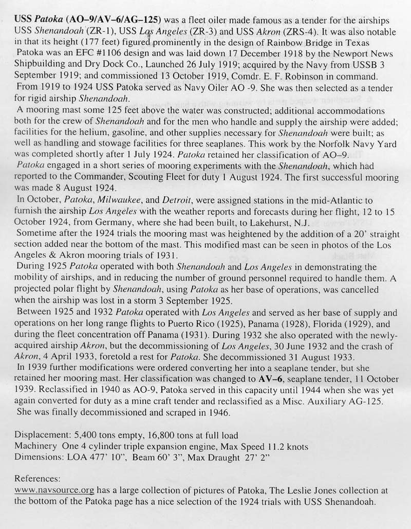
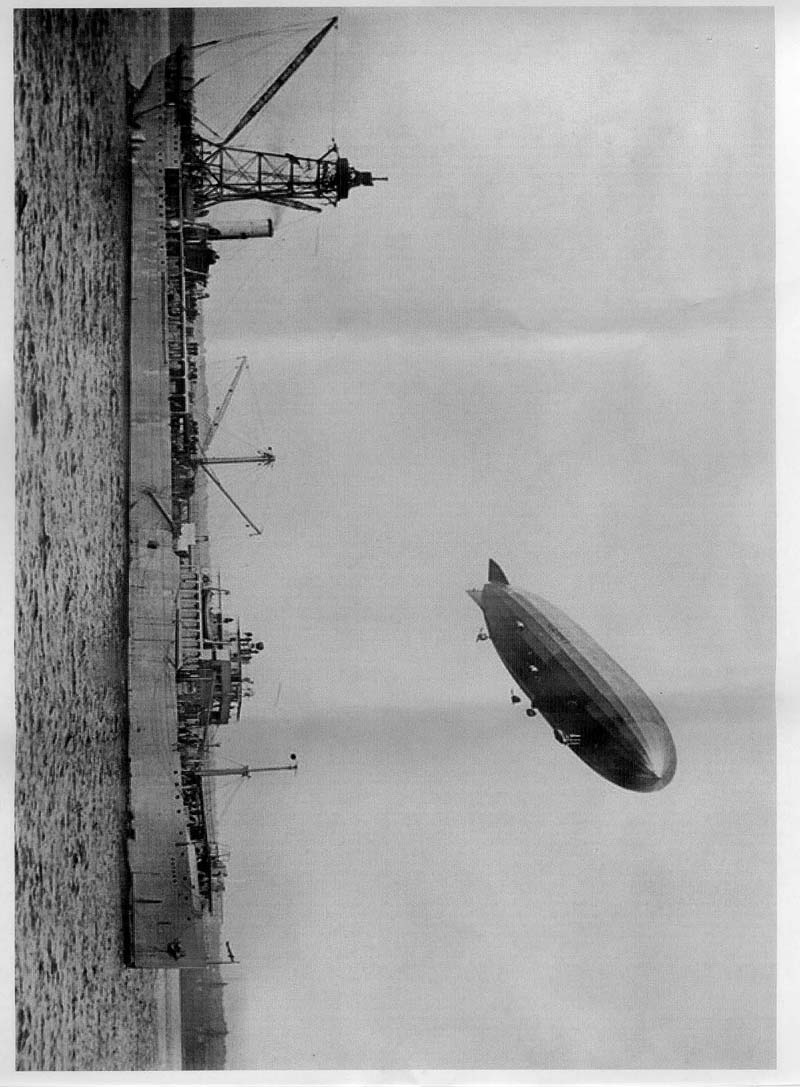
USS Patoka, a 16,800-ton oiler, was built at Newport News, Virginia. Commissioned in October 1919, she transported oil fuel from the United States to European ports during the next few years, as well as performing other support services in both the Atlantic and Pacific. In 1924 Patoka was modified as a tender for the Navy's rigid airships, receiving a distinctive mooring mast on her stern and facilities for handling seaplanes. She was subsequently used as an operational and experimental base by three of the Navy's great dirigibles, USS Shenandoah (ZR-1) in 1924-1925, USS Los Angeles (ZR-3) in 1925-1932, and USS Akron (ZRS-4) in 1932. Decommissioned in August 1933, following the loss of Akron, Patoka remained in reserve for six years. Reclassified as a seaplane tender (AV-6) in October 1939, she was recommissioned a month later and served briefly in that role, primarily in the Atlantic area. In June 1940, she returned to her original mission as an oiler, and was again designated AO-9. By late 1941, after carrying oil and other cargo in the Atlantic and Caribbean areas during the previous year and a half, Patoka had taken station at Recife, Brazil. She served there for most of World War II as a supply and repair ship for U.S. Naval forces operating in the South Atlantic. She also was employed as a personal and logistics transport during this time, and in early 1942 patrolled off Brazil in an effort to intercept enemy ships bringing vital cargo from the Japanese Empire to Europe. In 1945 Patoka was refitted to serve as a tender for minecraft in the Pacific. Given the new hull number AG-125 in August, she spent the last four months of the year, and the first part of 1946, supporting mine clearance and other aspects of the occupation of Japan. USS Patoka returned to the United States in March 1946 and was decommissioned at the beginning of June. Soon transferred to the War Shipping Administration and stricken from the list of Naval vessels, she was sold for scrapping in March 1948. |
||||||||||||||||||
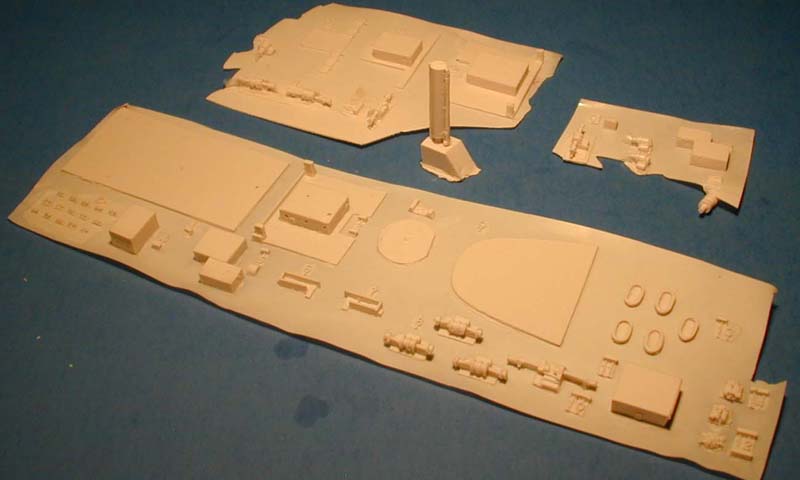
| HULL PARTS | ||||||||||||||||||
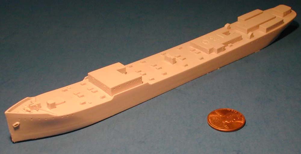
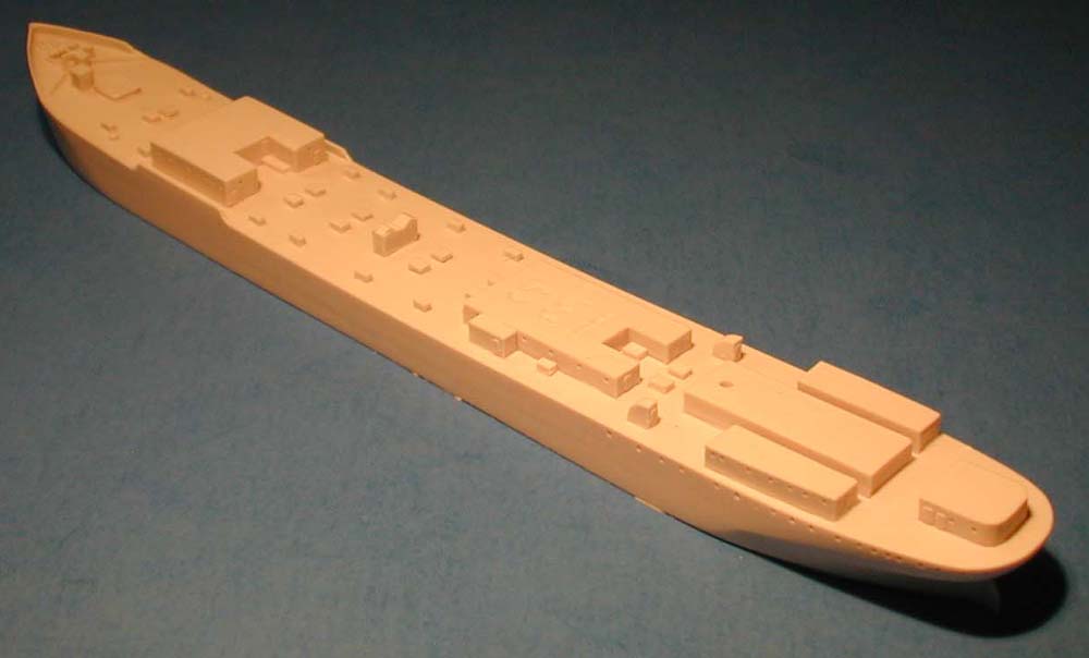
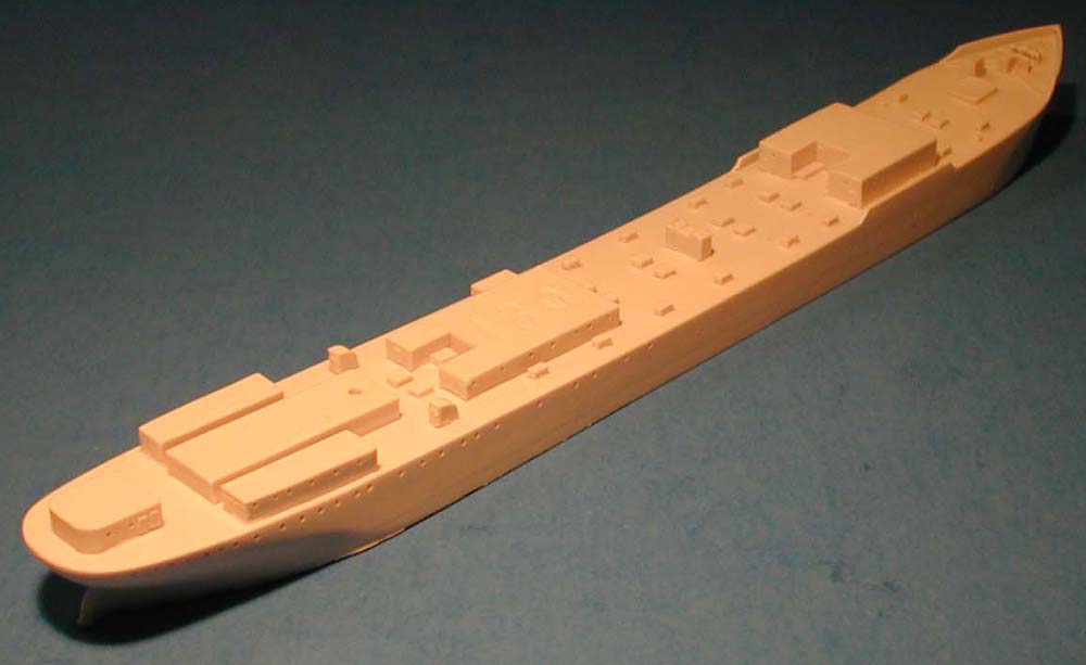
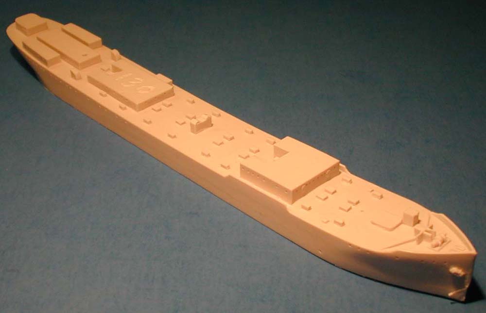
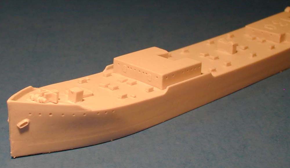
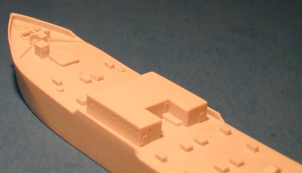
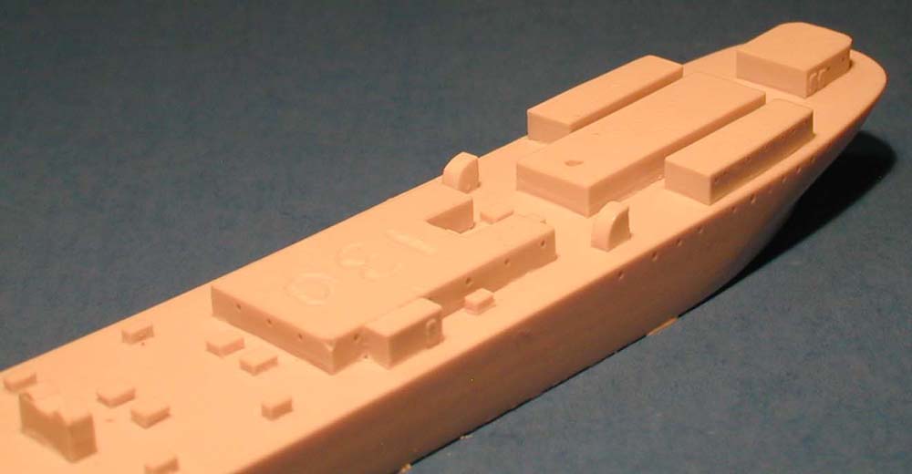
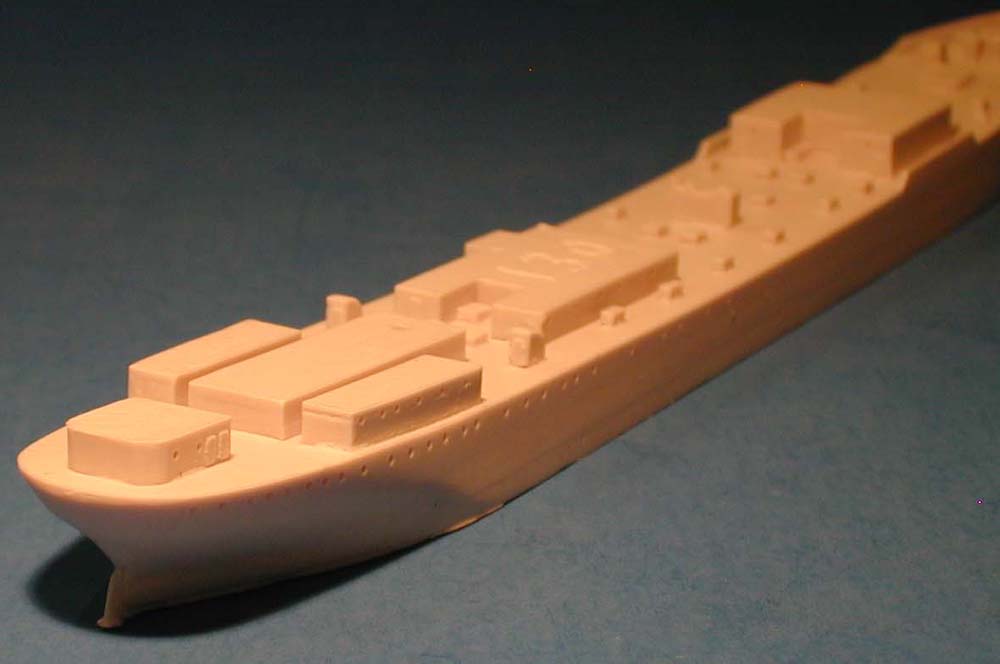
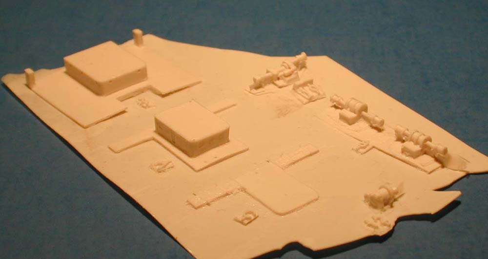
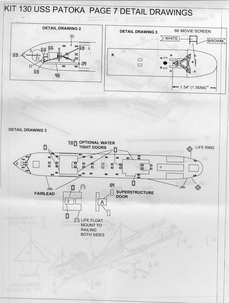
| The hull is cast in waterline style with part of the superstructure cast on. The deck and hull sides are pretty plain, but then so was the real ship. There are cast in portholes and cast on doors. The latter can be replaced with the included photo etch doors if the modeler desires. A nice deck winch is cast on forward of the breakwater on the bow. The lines of the hull appear to closely match the photos of the real ship. | Click images
to enlarge |
|||||||||||||||||
|
||||||||||||||||||
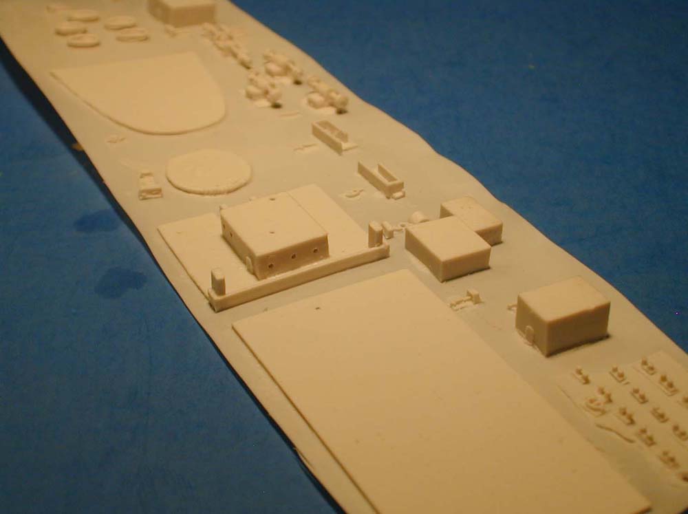
| SUPERSTRUCTURE | ||||||||||||||||||
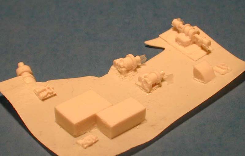
| The funnel, upper decks and a variety of nicely detailed winches and gear are cast on resin wafers. Detail is pretty good although care will have to be taken when removing them by flat sanding. | 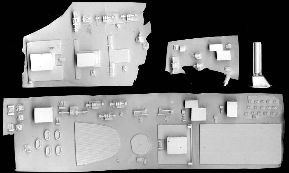 |
|||||||||||||||||
|
||||||||||||||||||
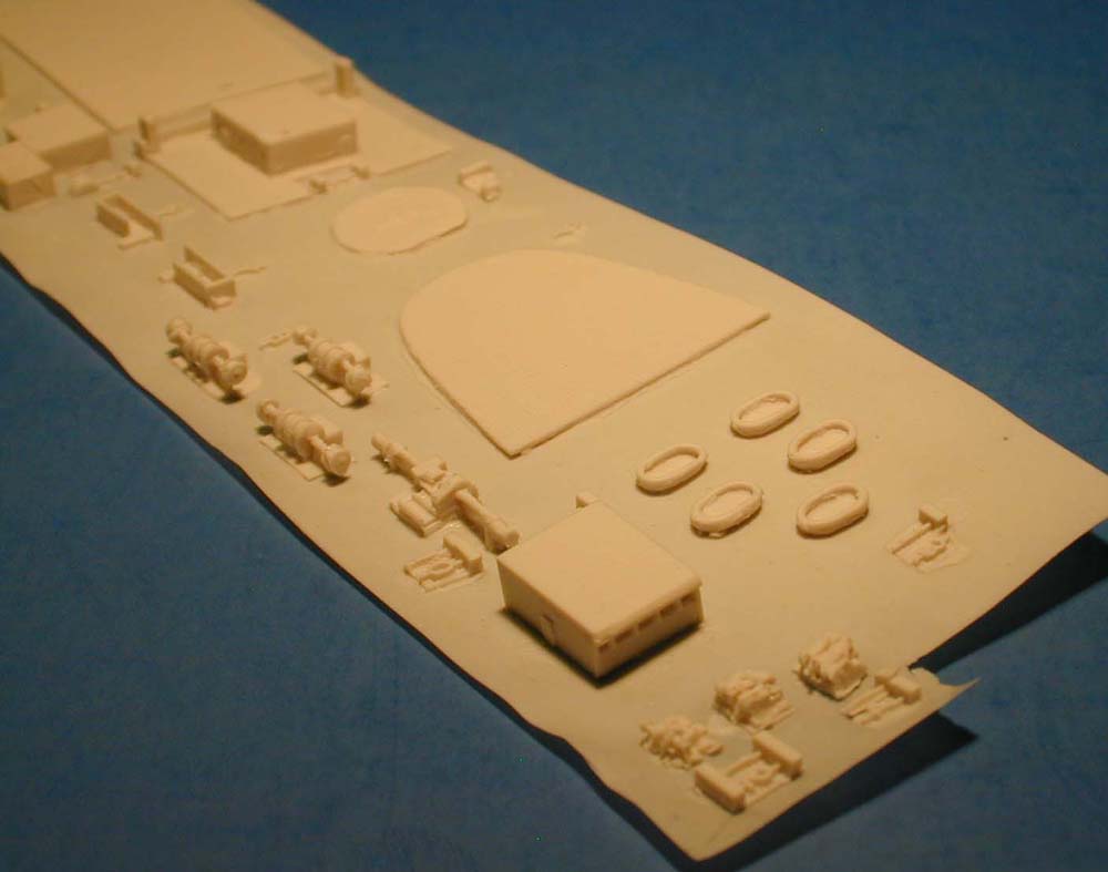
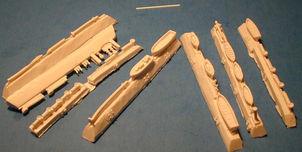
| BOATS AND FITTINGS | ||||||||||||||||||
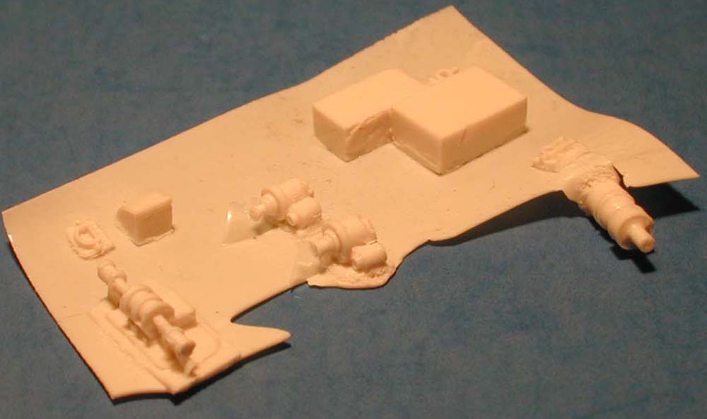
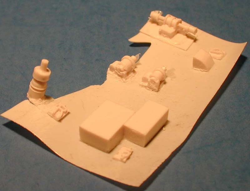
| The ships boats, vent pipes, and mast parts are cast on resin runners. The vents are well cast and I have to add that I love the numbered resin sprues! Sure makes it easier to identify the parts. | ||||||||||||||||||
|
||||||||||||||||||
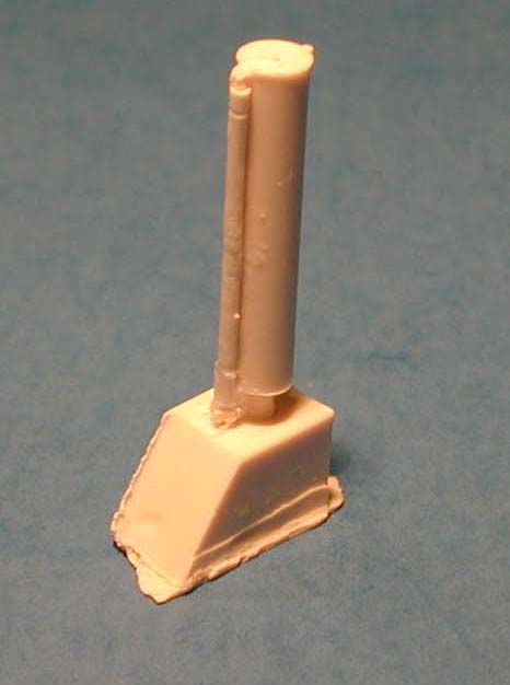
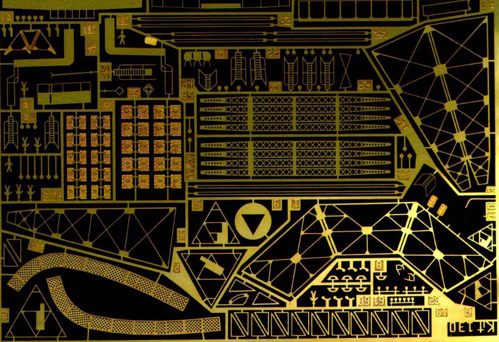
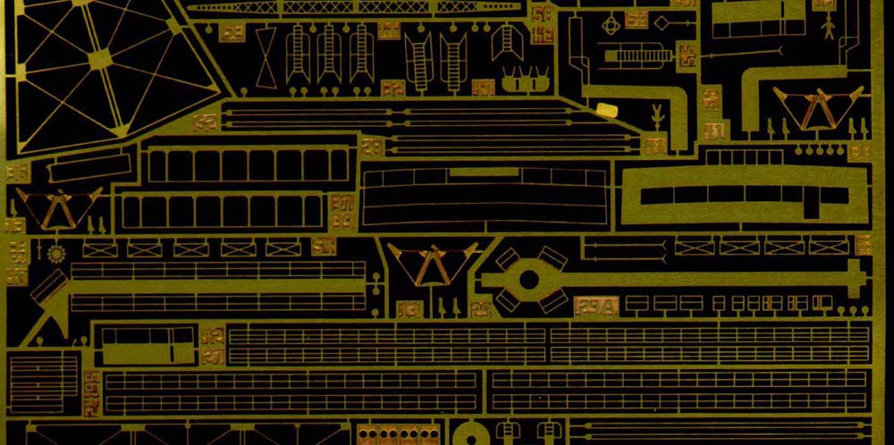
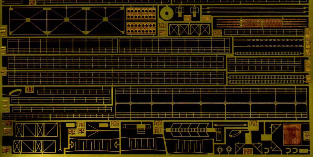
| PHOTO ETCH | ||||||||||||||||||
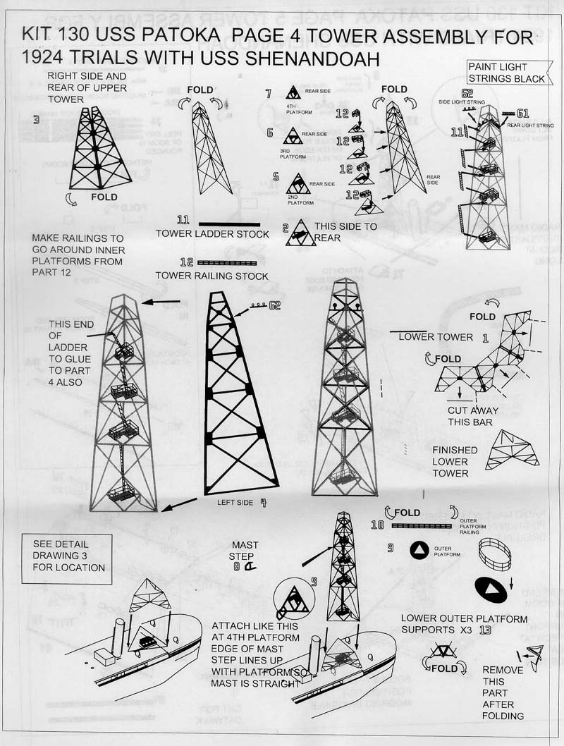
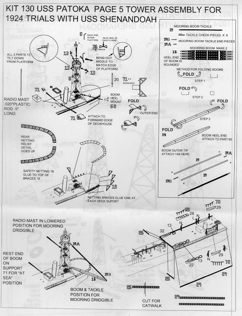
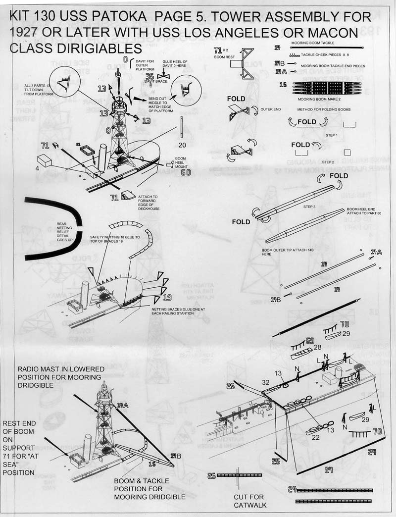
| A brass photo etch fret is supplied with railings, ladders, and especially the mooring mast. The latter is what really makes this ship. The mast has three distinct levels and a set of ladders and platforms that run up to the top. This will take some patience, but the end result should be stunning. The fret also has a number of other nice details including bridge face, platforms and rigging details. | 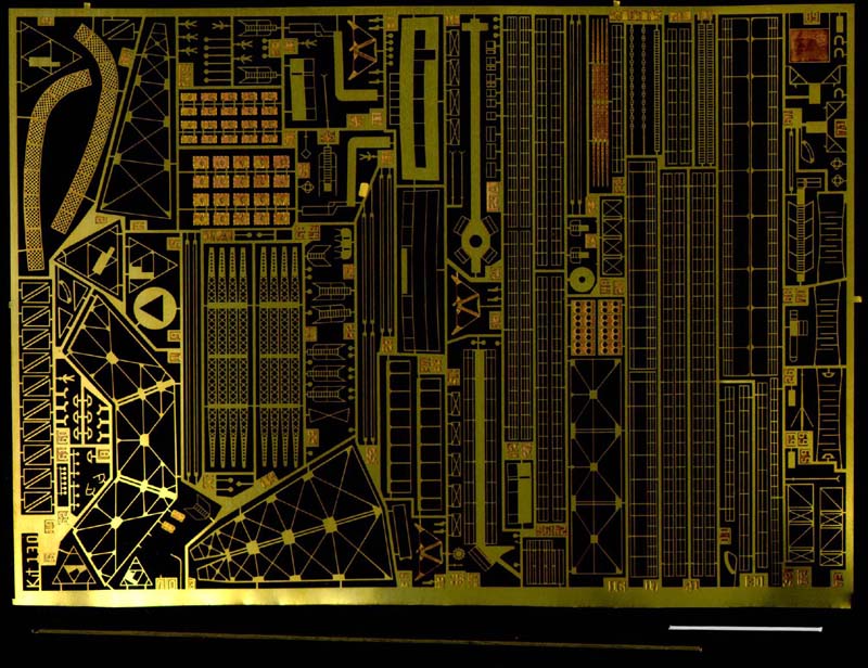 |
|||||||||||||||||
|
||||||||||||||||||
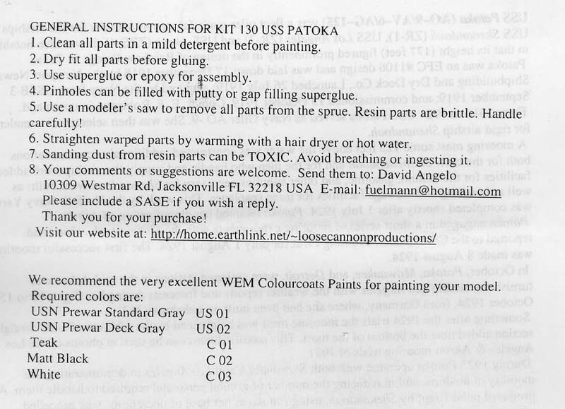
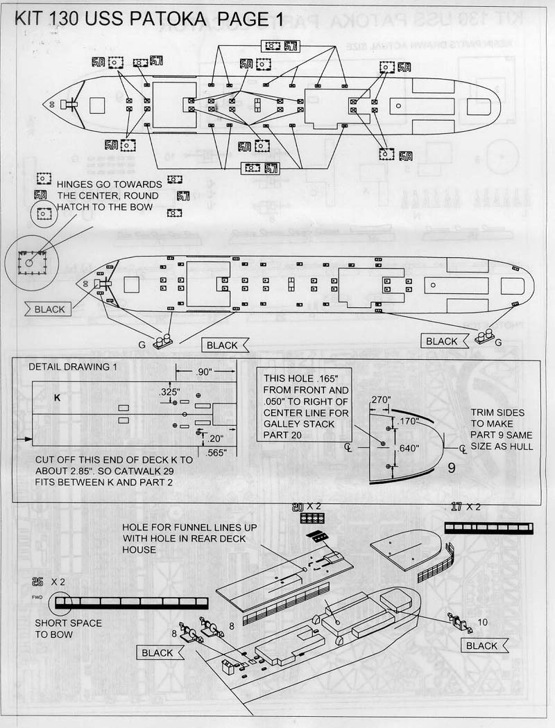
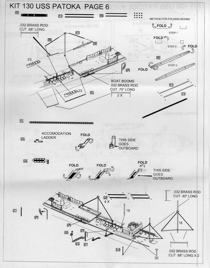
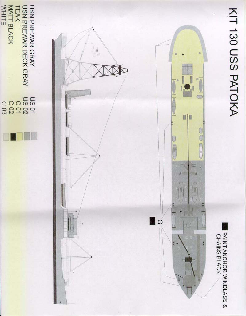
| INSTRUCTIONS | ||||||||||||||||||
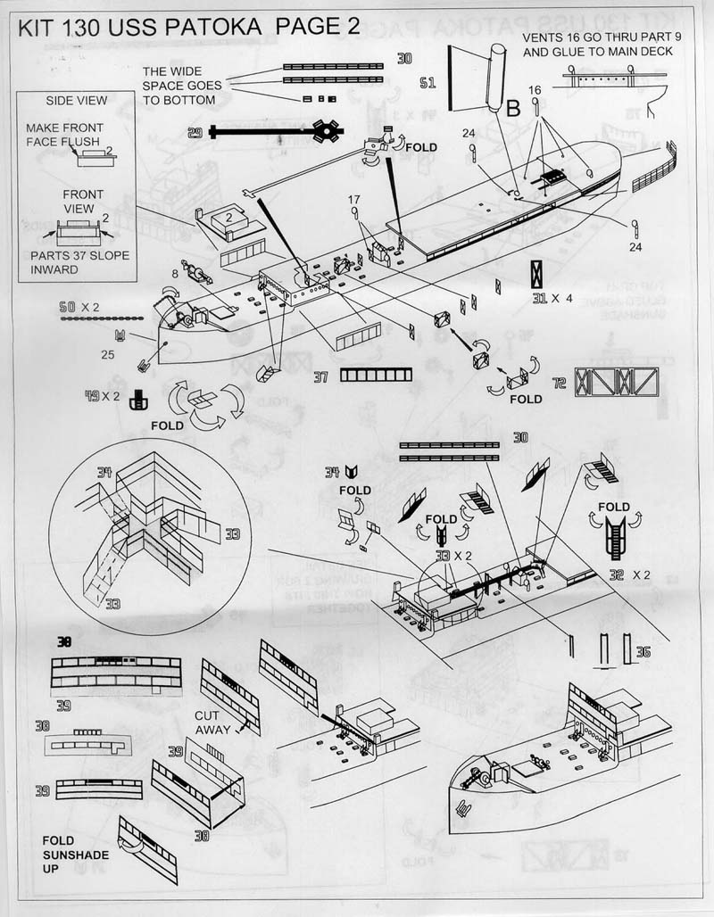
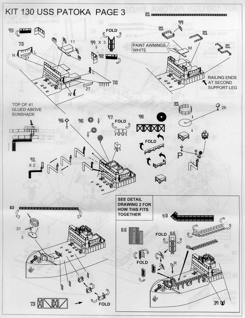
The instructions are fourteen pages with exploded assembly
views showing the various sub assemblies. A color painting guide and prototype
photos are also included. These are pretty extensive for such a small kit.
|
||||||||||||||||||
| Conclusions: | ||||||||||||||||||
Loose Cannon East has produced yet another obscure ship that will really stand out in your Auxiliary fleet. This one is not for beginners, but those who choose to tackle this subject will have a one of a kind ship, guaranteed to stand out in the crowd. Now all we need are some 1/700 Dirigibles to moor to that mast. This is Kit #130 - 1/700 USS Patoka listed for $60.00 US, a fair price for a complete kit with such an extensive photo etch fret. Check the Loose Cannon page for details on this and other kits. |
||||||||||||||||||