| Building the Faa Di Bruno in 1918
by Jim Baumann |
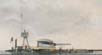
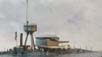
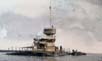
| On 1 January 1916 at the Venice Navy Yard the
Italian Navy launched their first purpose built monitor, the unique
Faa Di Bruno. The ship was commissioned on July 23, 1917. Surplus 15 guns
from the incomplete battleship Cristoforo Colombo were mounted in a twin
turret. The hull was of rectangular form, with a small deckhouse and small
stack aft; all access into the hull compartments being through the numerous
deck hatches. The deck sloped up on both sides to a ridge with a flared
heavily armoured barbette sitting midships. A 10 ft wide concrete armour
belt surrounded the entire hull. Faa di Bruno displaced 2584 tons; propelled
by two engines totaling 465 hp she was capable of achieving
3 knots
!
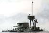
In WW1 she was used to Bombard Austro-Hungarian gun installations and shore units. At the end of hostilities Faa di Bruno remained in commission in the Navy until 1924. She escaped scrapping in the inter-war years and whiled away the time as a rusting hulk. In WW2 she was re-commissioned to serve as a floating Gun Battery and
renamed GM 194 and utilized as the harbour defense vessel for the port
of Genoa 1940-1943. Her AA armament was enhanced and upgraded and
she received an all-over camouflage scheme. Her eventual fate I was
unable to ascertain.
|
|||||||||||||||||||||
| Building the model: | |||||||||||||||||||||
| Regia Marina have produced a neat little kit for this unique vessel, consisting of a small number of resin parts and a small photo-etched fret. Unfortunately the kit appears to have been produced from a slightly erroneous drawings and somewhat unclear photographs, prior to the discovery of some fine close-up images, which were sent to me by Giampiero Galeotti of Regia Marina | Click images
to enlarge |
||||||||||||||||||||
| As such there are a few inaccuracies and errors . | |||||||||||||||||||||
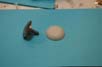
| The hull casting is dimensionally correct- and captures well the shape the vessel. Faa di Bruno sat low in the water; to present the model as she appears in photographs quite a lot of the lower hull needs to be removed. This was achieved using a bench-mounted belt sander immediately prior to mounting the model on its base, as otherwise the now wafer thin edges would be prone to damage. | 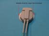 |
||||||||||||||||||||
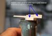
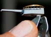
| Examination of the aforementioned photos showed the barbette to be too narrow at on the top face | 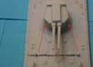 |
||||||||||||||||||||
| The barbette was missing the distinctive flare at its upper edge-which also accounted for the lack of width on the upper face of the barbette | 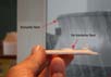 |
||||||||||||||||||||
 |
|||||||||||||||||||||
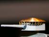
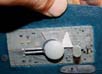
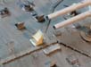
| Gluing on a styrene disc of the correct diameter created the flare;
backfilling up to the disc with auto-bodyfiller and sanding-in the hollow
using curved rifler files and fine wet and dry sandpaper wrapped around
metal tubes allowed the hollow curve to be created.
To make the edge of the flare and the top face of the barbette a sharp edge I pared and sanded away the styrene disc-this also kept the overall height in proportion. |
 |
||||||||||||||||||||
| At this stage I found myself staring endlessly at the photos on my
PC; zooming into images until I felt I knew the craft intimately. This
meant that I would end up cutting away much of the well rendered detail
and replacing it with even finer scratch built items!
I cut away the windowed square cast-on deckhouse. The deckhouse according to photos had no windows, had a right-angled extension on the port aft side and was topped with a curved not a flat roof! I fashioned this replacement from styrene block with a CA infused paper roof. |
 |
||||||||||||||||||||
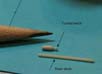
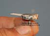
| The cast resin funnel aft of the deckhouse was cut awayand a new one made of copper tubing, with the lower mantle being a larger tube with the shoulders being made by filing and sanding; it was made over length for ease of handling and cut down later. | 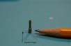 |
||||||||||||||||||||
| The edge of the sloping glacis of the hull was backfilled with thinned white glue-that self-levels- to almost eliminate the cast step-whilst retaining the outline of the concrete panels. | 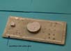 |
||||||||||||||||||||
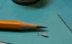
| The cast-on capstans and winches were removed-examination of photos showed these to be on raised pedestals with a remote winch brake. I turned these from resin stock in a mini drill using knife tips as the cutting tools. | 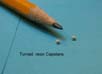 |
||||||||||||||||||||
 |
|||||||||||||||||||||
| I chose to open the hatches-as they would have been with the vessel moored. To gve them a sense of depth I opened the aperture right through the hull, once set o a dark base the illusion of a large deep recess was complete | 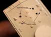 |
||||||||||||||||||||
| After the hatches had been cut through I laced the hull on a beltsander to simulate full load. I again inserted a self-tapping screw( No 6 in a 3mm dia drilled hole) to enable me to hold the model in my spring loaded clamp for ease of working on prior to mounting. | 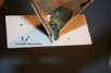 |
||||||||||||||||||||
| I also inserted a screw into the underside of the 15in
turret to permit holding and painting of the turret in one of my big springloaded
clamps.
I was not entirely satisfied with the turret shape when compared to the close-up photos I had been sent- and I glued on styrene strip to permit the reshaping of the turret. |
 |
||||||||||||||||||||
 |
|||||||||||||||||||||
 |
|||||||||||||||||||||
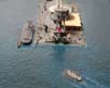
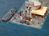
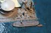
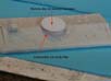
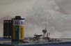
| The time came to mount the vessel upon its base; the water being made, as is my usual way; of embossed artists watercolour paper. To further garner the illusion of looking through the hatches into a deep cavernous hull I continued the holes in the base. The watercolour paper was cut out so that the hull edges sat flush with the surface of the water. |  |
||||||||||||||||||||
| The sloping decks of Faa-di Bruno would have made continuous fore-and -aft transiting of the decks very wearing on the ankles and legs of the crew, so the ship was fitted with walkways that were angled to be horizontal. These were absent from the kit. I fashioned these and the supporting legs by cutting WEM 1/350 KGV degaussing cable, bending the straps down to form legs and mitring the corners according to my interpretation of photos. | 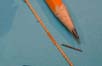 |
||||||||||||||||||||
 |
|||||||||||||||||||||
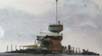
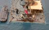
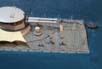
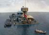
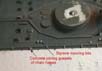
| The model was secured to the base with glue and a screw through into the barbette. I started adding as much additional detail as I could extract from the photos. The twin heads and central watertank aft were carved from styrene strip material; extra hatches were fitted and a large number of securing and tie down points simulated with a dab of white glue or a pencil circle The mast tripod legs suggested in the instructions were far too high-I scaled mine off a side elevation photograph. When the vessel was static the spotting top viewing slots were covered with a canvas curtain. I used paper strip sprung in place to simulate this, once installed I infused this with CA for rigidity. I added a strong support for the spotting top roof so as to unload the paper and make alignment easy. Unusually the tripod legs did not meet underneath the spotting top but were held apart with a number of pierced gussets. I replicated these by cutting and shaping PE boat cradles (WEM). I also added voice communication pipes of thin copper wire as well as waste drains as far as I could discern from my endless staring at photos | 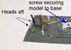 |
||||||||||||||||||||
 |
|||||||||||||||||||||
 |
|||||||||||||||||||||
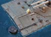
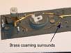
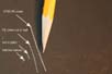
| The concrete armour surrounding the hull appeared to be
contained by steel strapping and was connected to the steel hull with steel
brackets. Whatever their function or material I attempted the replication
by cutting sections of 1/700 chain in half and folding small sections.
The outline was now close to the real thing, and I infilled the
apertures in the chain pieces with white glue to give the impression of solidity. |
 |
||||||||||||||||||||
 |
|||||||||||||||||||||
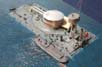
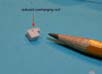
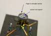
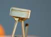
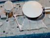
| A distinctive feature of this vessel was the armoured cupola
over the turret top. I was much attracted to this feature and wanted it
to look just right. The profile of the resin item within the kit was incorrect
when examined with photos, so a replacement was turned on a lathe using
a curved top steel coachbolt.
Unfortunately the steel was of poor quality and it proved difficult
to create a clean undercut on the inside of the bolt.
|
 |
||||||||||||||||||||
 |
|||||||||||||||||||||
 |
|||||||||||||||||||||
 |
|||||||||||||||||||||
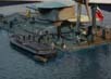
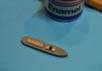
| To liven up the scene of the static moored vessel I carved a small
lighter from some scrap resin ( old WEM Hood turret!). This was fitted
with a styrene coaming and some PE hatches ( GMM 1/426 Arizona!! )
I drilled through the underside to create a deep hatch and cut open one of the lids on the lighter. |
 |
||||||||||||||||||||
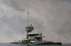
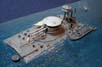
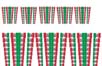
| Thereafter I added more and more detail. Awning stanchions
were contained on a small PE fret within the kit; but I wanted mine somewhat
finer still
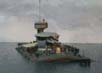
I cut 1/350 PE superfine handrail longitudinals and installed them into drilled holes; supporting struts were made of stretched sprue. I wanted to add the awning on the starboard side; despite this obscuring much detail it did add to the overall balance of the scene. The awning sections were made by dragging a film of thinned white glue across a framework made of thin copper wire and stretched sprue (simulating the supporting cables) This was eventually successful- but as can be seen from the photos there were also a few failures! These long wide spans were at the absolute limit that a white-glue film will span without collapsing. At the aft end I bunched some white glue drops to simulate a further panel tied and furled. |
 |
||||||||||||||||||||
 |
|||||||||||||||||||||
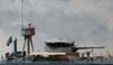
| Whilst the white glue was on the bench I added new brass wire barrels
to the 4 AA guns and subsequently made canvas covers using repeated layers
of white glue.
The guns were mounted on the neat PE platforms supplied; supporting legs for these were made using cut down 1/700 handrails. The PE Anchors at the bow were modified from GMM items; a very fine
tapered top mast was made for me by Steve Foulkes, PE hatches were in the
main WEM and a vent stack was made and fitted with a circular lid.
The Regia Marina Ensign I printed on to white Decal sheet on my PC using
some flag artwork I had created for my previous 1/350 Roma project( in
Serif drawplus8)-I simply copied and resized the flags to 1/700 and chose
the appropriate size.
|
 |
||||||||||||||||||||
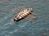
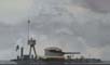
| To help balance the scene a rowing gig was placed approaching the stb aft quarter of Faa di Bruno; with the ratings pulling hard | 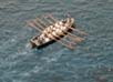 |
||||||||||||||||||||
| The open fairleads were supplied on the kit PE fret-however upon examining
close-up photos I noticed that on the real ship these were a flat casting-so
I made my own from very thin brass strip. The ship was moored using PE
chain twisted so as to give it some more three-dimensional qualities. The
large mooring buoy was made of styrene tube with a band of brass strip
at the top.
The main crew entry hatch on the ridge of the foredeck had a canvas hatch cover; this was fashioned of small PE scrap to form a frame and draped with canvas using white glue |
 |
||||||||||||||||||||
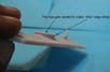
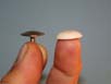
| In conclusion: | |||||||||||||||||||||
| I thoroughly enjoyed this project, the challenge of research using
the pictures available and separating and collating the various eras of
fit.
Regia Marina must be congratulated upon marketing such a fascinating and even bizarre vessel. The shortcomings of the kit I feel can probably be attributed to a commonly known but misleading drawing and the probable unavailability of the photos that I subsequently had the benefit of ! Faa di Bruno is NOT a large model, the hull measuring a shade over 3 inches loa |
 |
||||||||||||||||||||
|
|||||||||||||||||||||
| My thanks to:
Giampiero of Regia Marina for his photos and support Steve Foulkes for skills with cupola turning and extreme tapering of masts. |
|||||||||||||||||||||
| Bibliography: | |||||||||||||||||||||
| NAVI E MARINAI ITALIANI
NELLA GRANDE GUERRA Erminio Bagnasco & Achille Rastelli |
|||||||||||||||||||||
More
of Jim Baumann's work.
Updated 12/16/2008

© ModelWarships.com