| History | ||||||||||||||||||||||||||||||||||||||||||||||||||||
|
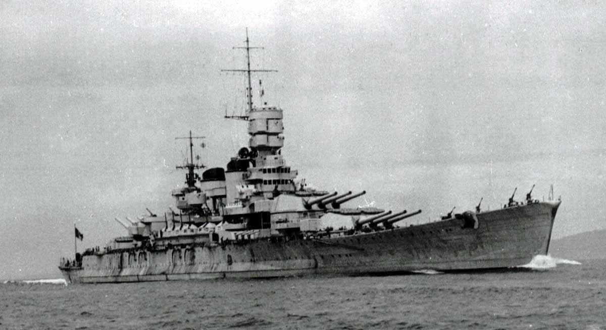
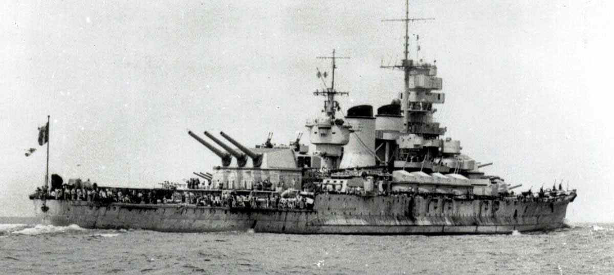
Built and commissioned at CRDA, Trieste, Italy. Roma was the third and last of the four-ship Littorio class of fast Battleships; the last hullImpero not being completed. Romas main visual differences to her sisters Littorio and Vittorio Veneto was her fuller and taller bow section as well as a different bridge window layout with reversed angle glazing. She steamed around 20 sorties, all without enemy contact On September 8 1943 in company with most of the remaining Italian fleet, Roma set off from La Spezia to surrender to the Allies after the Italian armistice. Roma was the Flagship of Admiral Carlo Bergamini Flagship who commanded the fleet which included two other battleships, Vittorio Veneto and the re-named Italia ( ex Littorio), three cruisers along with eight destroyers. The following day the ships were spotted and attacked by 15 German Dornier Do 217 aircraft near the Asinara island (northern Sardinia ) The fleet had been ordered to open fire only in the event of being attacked, and the order was respected initially. However, when the fleet finally did open anti-aircraft fire, it was evident that the German planes were flying deliberately above the range of the Italian guns, around 5000 metres( 16,400ft) which was too high for conventional bombing. Each airplane was equipped with a type FX-1400 bomb originally named FritzX. The FX-1400was a high penetration 1400 kilo device with four small wings, tail controls and a rocket motor. in the vicinity of the tail was installed a radio-control system controlled by the aircraft deploying the bomb. The first ship to be hit by the new weapons was the Italia ( ex Littorio),which was able to maintain speed; thereafter Roma was then struck twice. The first hit was midships penetrating the deck and then exploding underneath the ship, reducing its speed to 10 knots. Shortly afterwards the second bomb hit the deck just aft of B turret, exploding with such force that the turret was thrown clear over the side, damaging the boilers and detonating the main magazines. As the ship exploded she split in two and sank. 2 Admirals, 86 Officers and 1264 sailors were lost. 596 survivors. Roma was the first major ship to be sunk by a guided missile
|
||||||||||||||||||||||||||||||||||||||||||||||||||||
| Kit preview | ||||||||||||||||||||||||||||||||||||||||||||||||||||
In-box kit review here at modelwarships.com. |
||||||||||||||||||||||||||||||||||||||||||||||||||||
| Building the model: | ||||||||||||||||||||||||||||||||||||||||||||||||||||
|
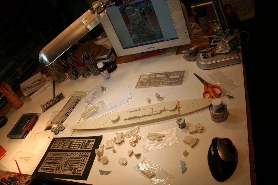
The Axis Roma was eagerly and long awaited by the ship-modelling world. It was intended to be a cutting edge technology kit- with much of the mastering being done digitally. After a somewhat protracted gestation, when it finally arrived -and the missing barrels and Photoetch caught up with the resin kit parts that had been dispatched earlier it was time to think about tackling the building of this much vaunted ship model. For a variety of reasons no instructions were issued with the kit, although a good quality drawing in 1/350 scale was included in the box. It is fervently hoped that this article will be of some assistance to other budding Axis Roma builders. The lack of instructions was initially somewhat daunting-and certainly contributed to the extraordinarily long build time of nearly six months . |
||||||||||||||||||||||||||||||||||||||||||||||||||||
|
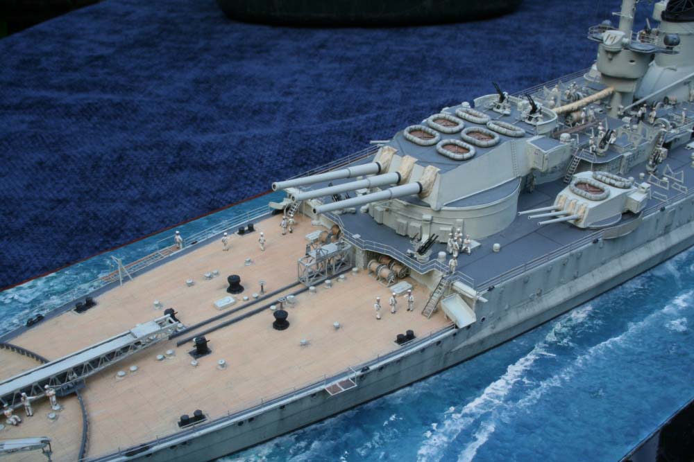
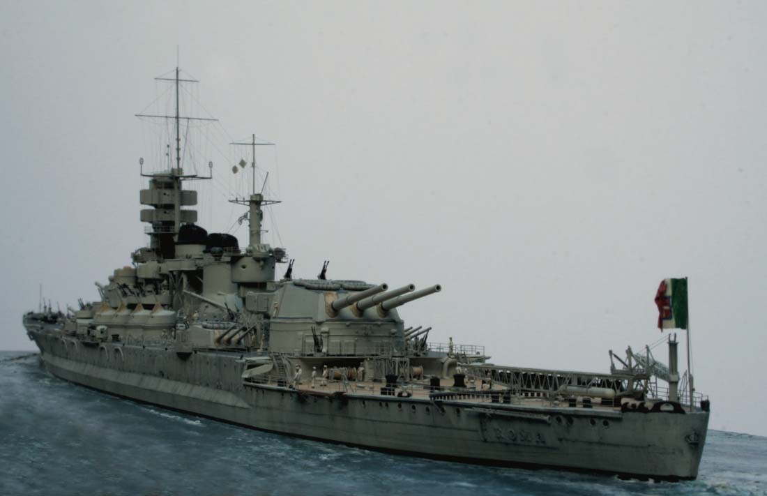
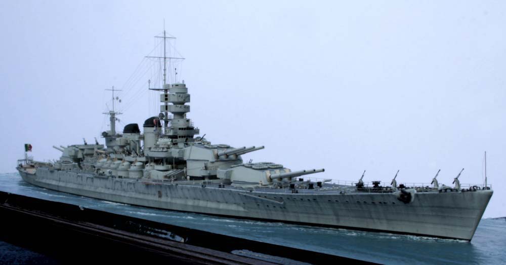
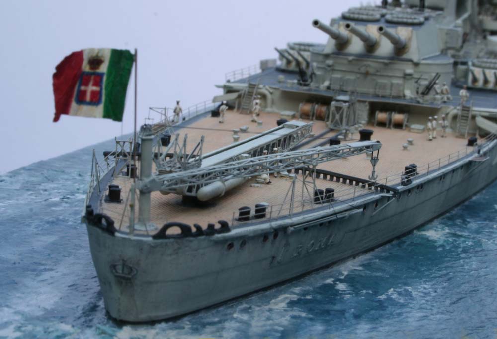
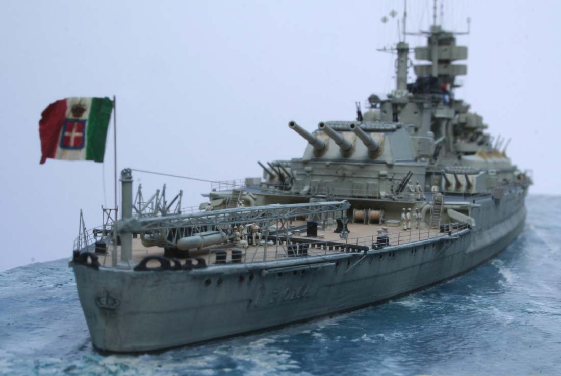
After acquiring a number of high res photos of the ship, and endlessly studying the plans and photos I decided I wanted to portray Roma as at trials.
|
||||||||||||||||||||||||||||||||||||||||||||||||||||
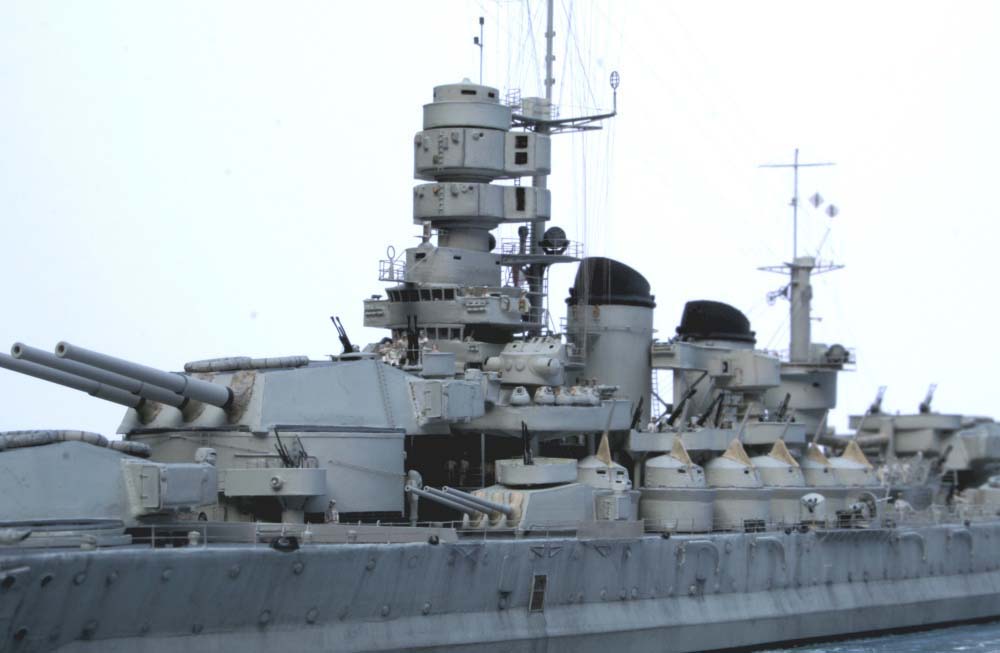
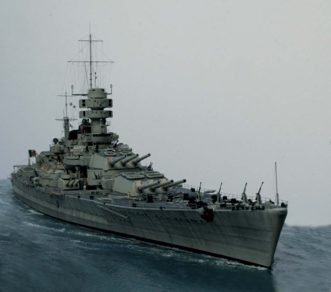
| A time when the superstructure was clean and crispand
the hull was streaked and dirty. This allowed me to show the handsome lines
of this magnificent ship more effectively.
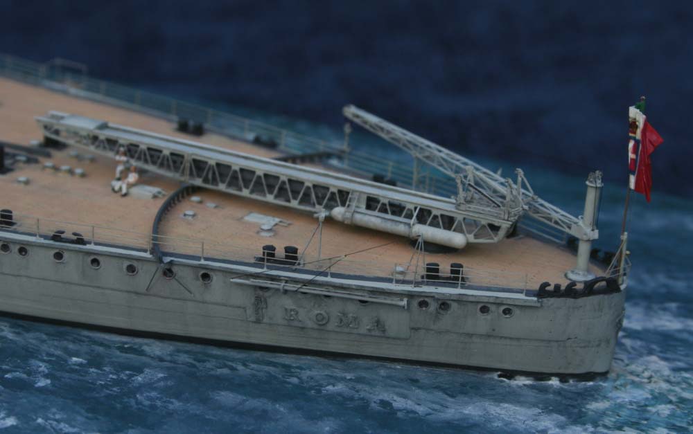
Roma was painted in a hard-edged splinter camouflage pattern of light and dark grey as soon as she was accepted from the builders and commissioned in the Italian navy. While it is visually striking - especially so with the red and white air recognition stripes on the bow; the scheme broke up her outline too much- which of course was the intended purpose of the paint scheme! Once I had decided upon the era and level of fit I immediately opted for a waterline displayas the vast expanse of the underwater hull would detract from the remainder of the ship. The choice of era had advantages as well as disadvantages. The photographs of Roma at trials showed various omissions from the final fit such as Gufo radar equipment, second pair of searchlights on mainmast platform, canvas skirts on the AA turrets, canvas dodgers on some bridge and mainmast platforms, stern depth-charge racks, -as well as the lack of depth charges in the quarterdeck racks, but by far the most obvious is the lack of a single ships boat along with the absence of aircraft. Despite being included with the kit, the fine miniature aircraft with their neat PE wings in the interests of historical accuracy I could not permit myself my selfish visual indulgence of placing boats and aircraft on my Roma! |
||||||||||||||||||||||||||||||||||||||||||||||||||||
| There was much fine plating detail on the hull, which would be lost forever | 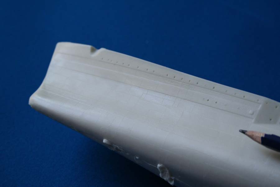 |
|||||||||||||||||||||||||||||||||||||||||||||||||||
| Many of my model making colleagues felt it was sheer sacrilege to turn
the handsome hull to dustbut I was certain this was the way ahead for
my Roma!
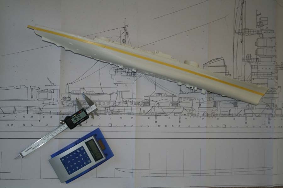
After establishing the true waterline from the 1/100 plansand with the aid of a digital Calliper gauge and a calculator marked this off on the hull with Tamiya masking tape |
 |
|||||||||||||||||||||||||||||||||||||||||||||||||||
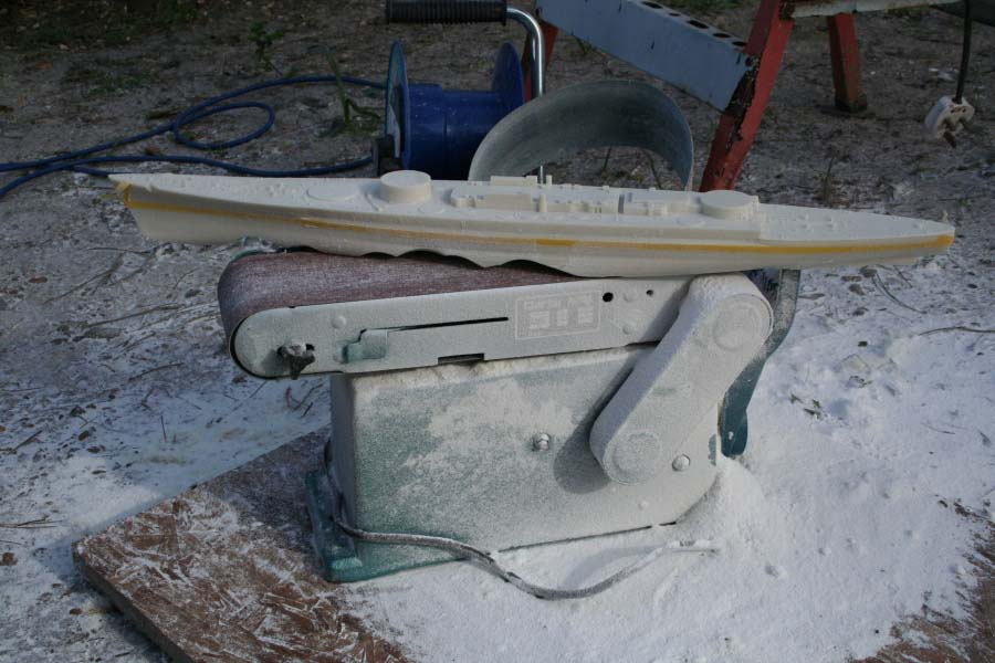
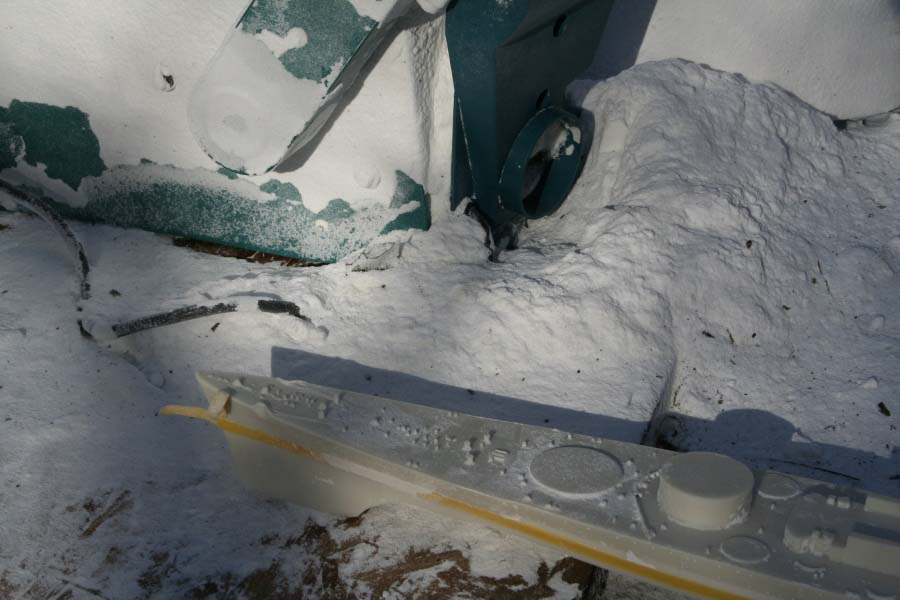
| The actual waterlining was done using a benchmounted beltsanding
machine.
The technique I found most effective was to use the drive wheel end
to make a set of arches in the lower hull. Thereafter to even these out
and make the hull fairthis helps prevent the machine from stalling or
burning the motor out.
|
 |
|||||||||||||||||||||||||||||||||||||||||||||||||||
 |
||||||||||||||||||||||||||||||||||||||||||||||||||||
| I then left the hull for a few weeks to see if there would
be any warpage or movement within the now much reduced casting.
In the meantime I had been supported extensively in my quest for information by Giampiero Galleoti of Regia Marine Models, and was making concrete plans of assault. My on-line discovery of the truly breathtaking 1/100 scale model of the Roma by Mr Barbieri. ,which had taken him over 10 years of work to painstakingly construct to the very highest standards I have ever seen anywhere- and the extensive on-line photo coverage of this pinnacle in modelmaking quality meant that my enthusiasm made me commence my build of the axis model in earnest! This link to high resolution images was always inspiring as well as instructive. |
||||||||||||||||||||||||||||||||||||||||||||||||||||
|
However, the Barbieri Roma model- although being probably one of the very best ship models in the world, shows a utopian level of fit; because Roma was completed during wartime, she had various features omitted, moved and changed. As a result, in order to be accurate, it is essential to study photos of the chosen era of fit. |
 |
|||||||||||||||||||||||||||||||||||||||||||||||||||
|
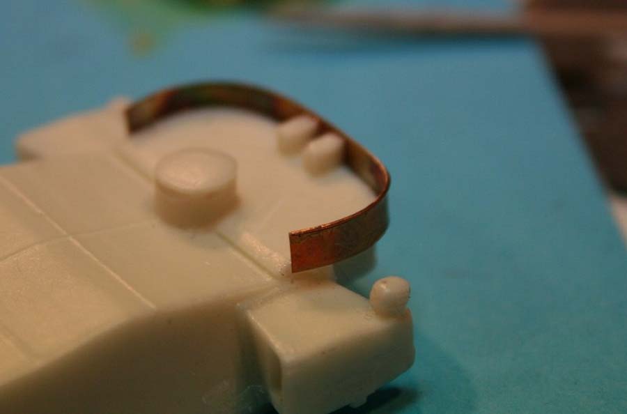
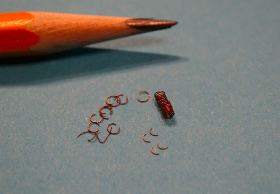
I started with some easy modifications, adding wind deflectors to some of the splintershields. This was simulated by the application of fine copperwire and CA glue, afterwards scraping away the inner resin face to suggest the rolled shape. |
 |
|||||||||||||||||||||||||||||||||||||||||||||||||||
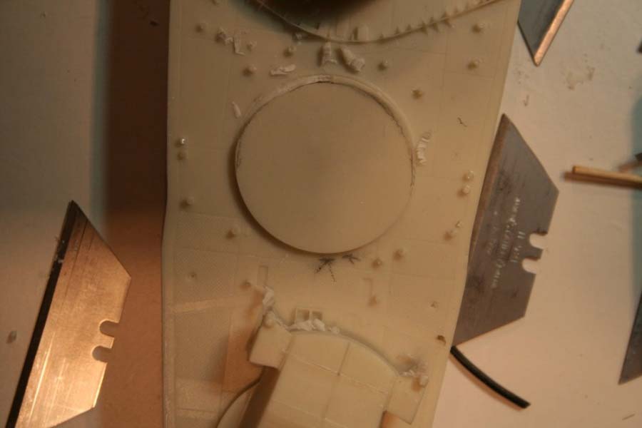
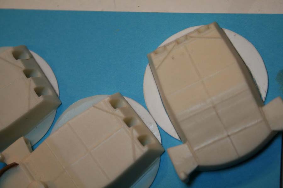
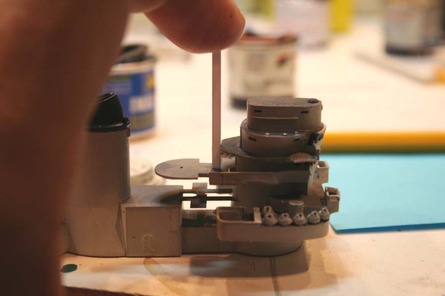
| I then addressed the first problem I had encountered in dryfit examinations of the kit. | 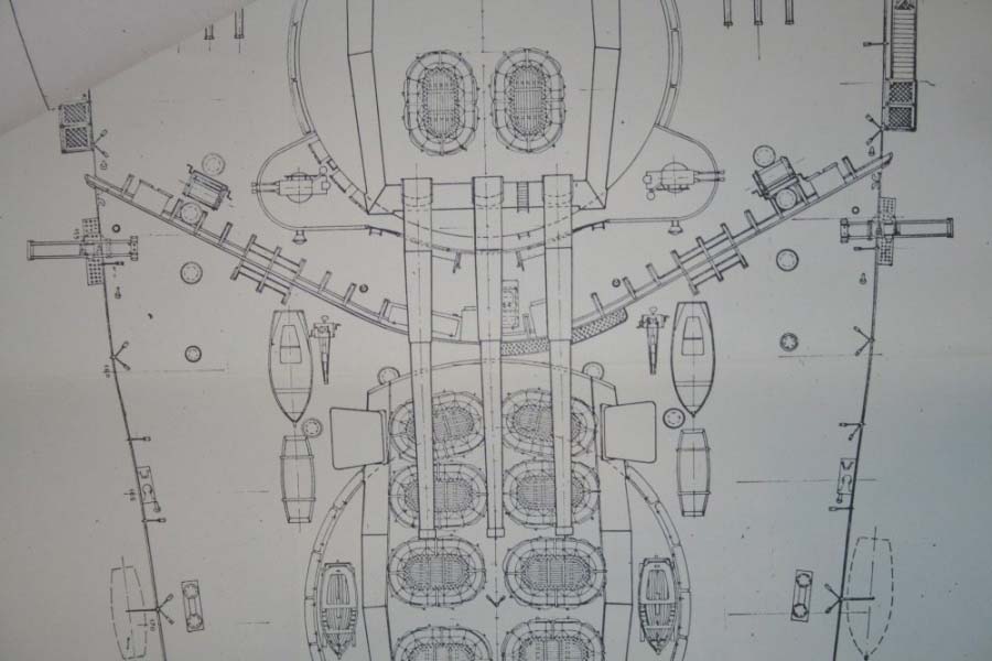 |
|||||||||||||||||||||||||||||||||||||||||||||||||||
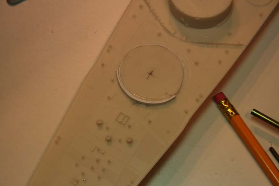
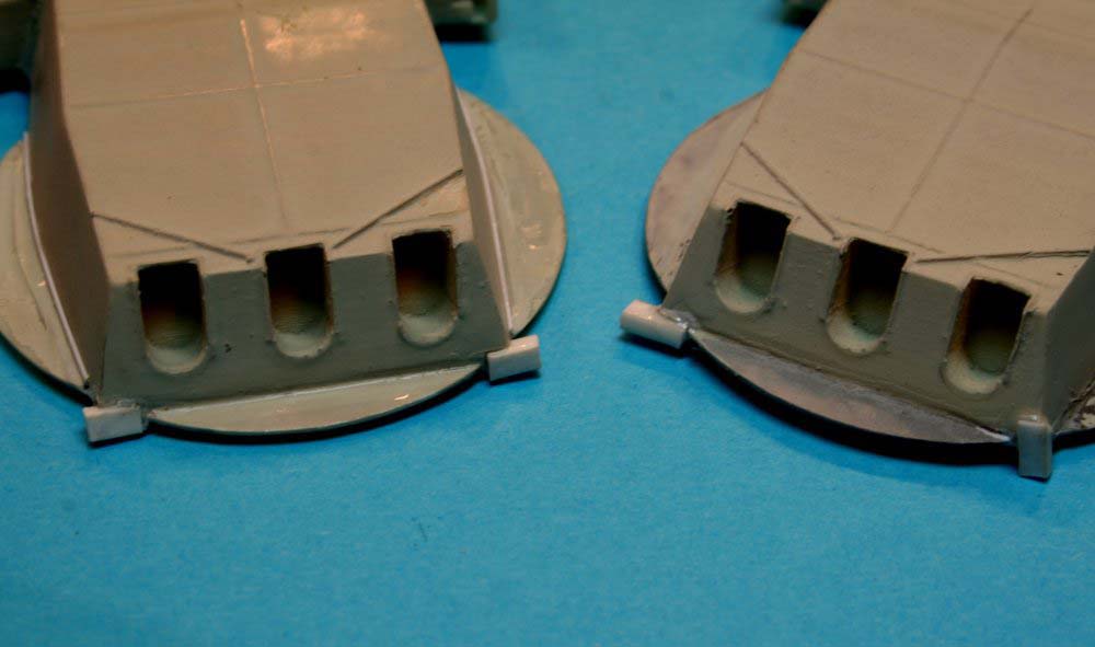
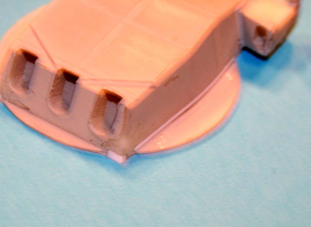
| Examination of the plans showed the fwd main turret to clear the breakwater, this was not the case in the model. | 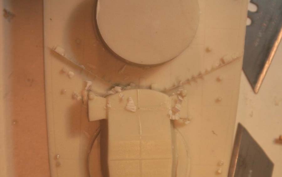 |
|||||||||||||||||||||||||||||||||||||||||||||||||||
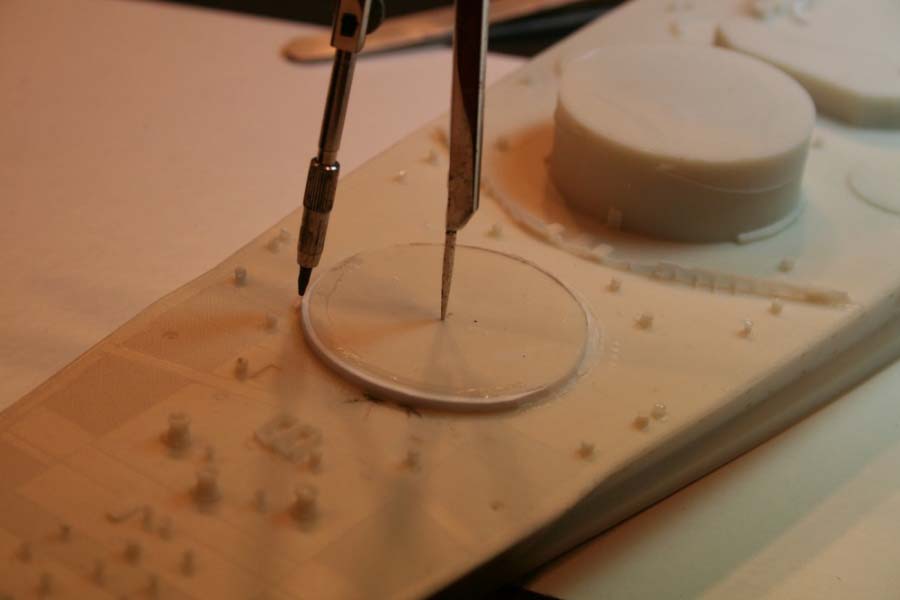
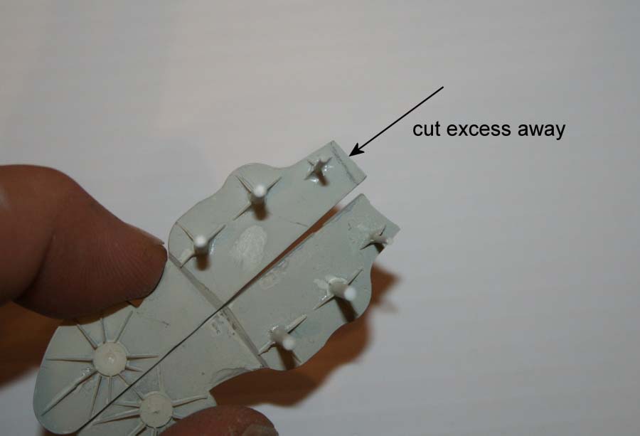
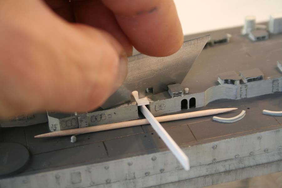
| I measured and re-measured the turrets-which were within
acceptable fractions of millimetres; and concluded that the position of
the fwd barbette within the hull was a bit out.
Fortunately Roma had a steel deck in this areaso the moving fwd of the barbette by 2.5mm was not as fraught a task as it would have been otherwise. I first cut away the surplus material aft, and then added styrene strip material on the front face and with a compass drew the true shape. After some paring, trimming and sanding the barbette was now in a better position. |
|
|||||||||||||||||||||||||||||||||||||||||||||||||||
 |
||||||||||||||||||||||||||||||||||||||||||||||||||||
 |
||||||||||||||||||||||||||||||||||||||||||||||||||||
 |
||||||||||||||||||||||||||||||||||||||||||||||||||||
|
I then carefully repaired the cast breakwater-which was a waste of time-as there was a perfectly formed PE replacement suppliedcomplete with fine pierced gusset brackets!! |
 |
|||||||||||||||||||||||||||||||||||||||||||||||||||
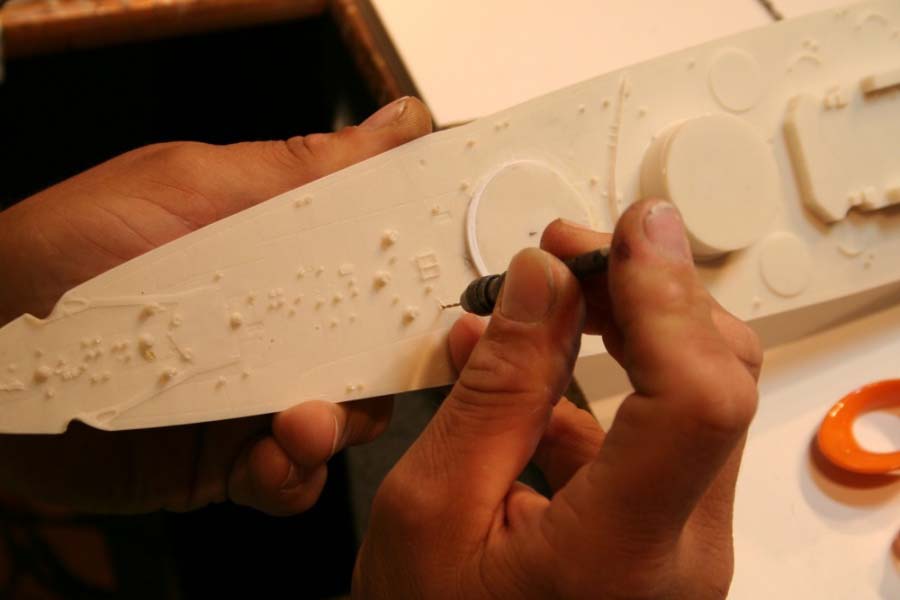
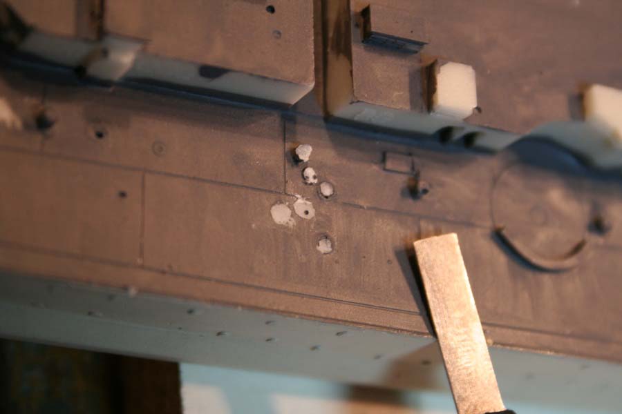
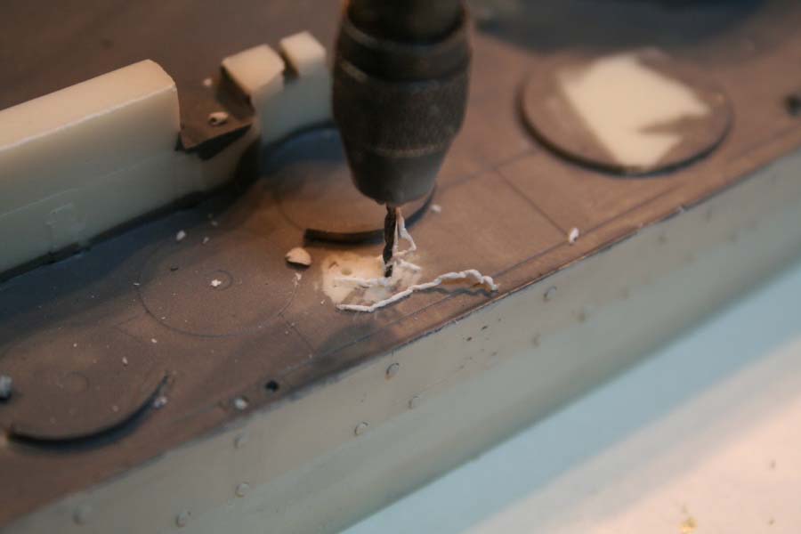
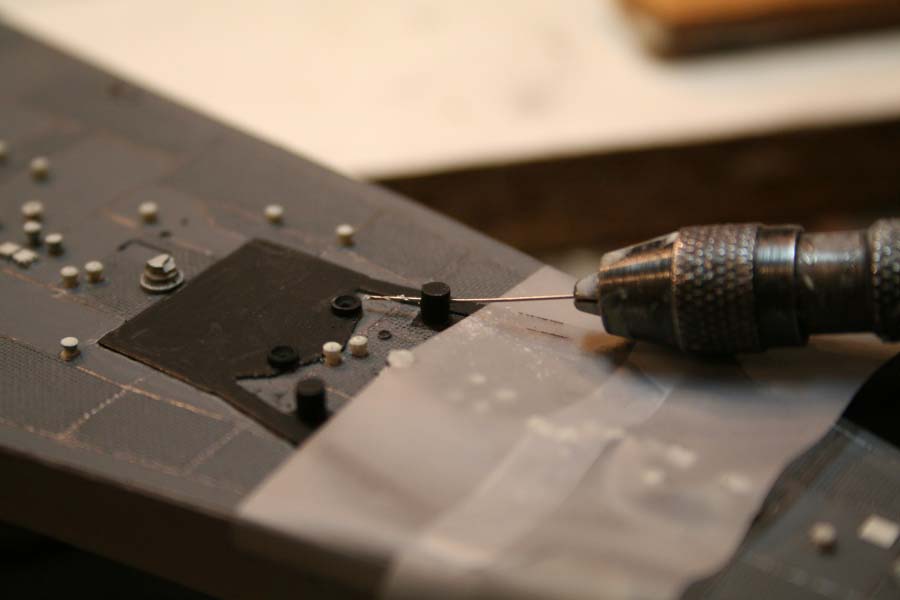
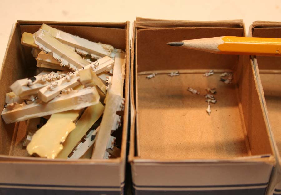
| Many of the numerous cylindrical deck vents were miscast, damaged or had air bubbles. Fortunately there were extensive cleanly cast spares supplied so I set to removing all the offending items using a curved Rifler file and drills in pin-chuck to mark their locations. | 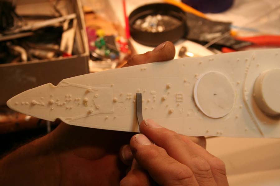 |
|||||||||||||||||||||||||||||||||||||||||||||||||||
 |
||||||||||||||||||||||||||||||||||||||||||||||||||||
 |
||||||||||||||||||||||||||||||||||||||||||||||||||||
 |
||||||||||||||||||||||||||||||||||||||||||||||||||||
| I then removed the cast aft deck overhanging strake, drilled out the portholes, | 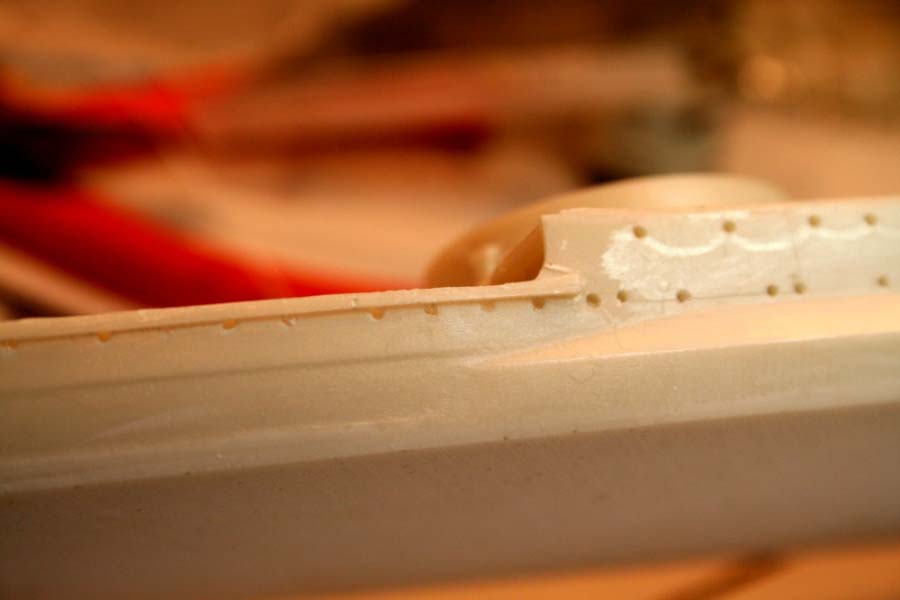 |
|||||||||||||||||||||||||||||||||||||||||||||||||||
 |
||||||||||||||||||||||||||||||||||||||||||||||||||||
| I then proceeded to add the eyebrows to the portholes where appropriate using copperwire semicircles cut from a spiral of the wire formed around a drill shank. | 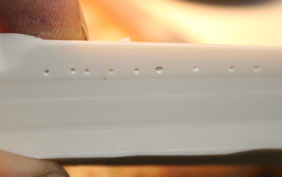 |
|||||||||||||||||||||||||||||||||||||||||||||||||||
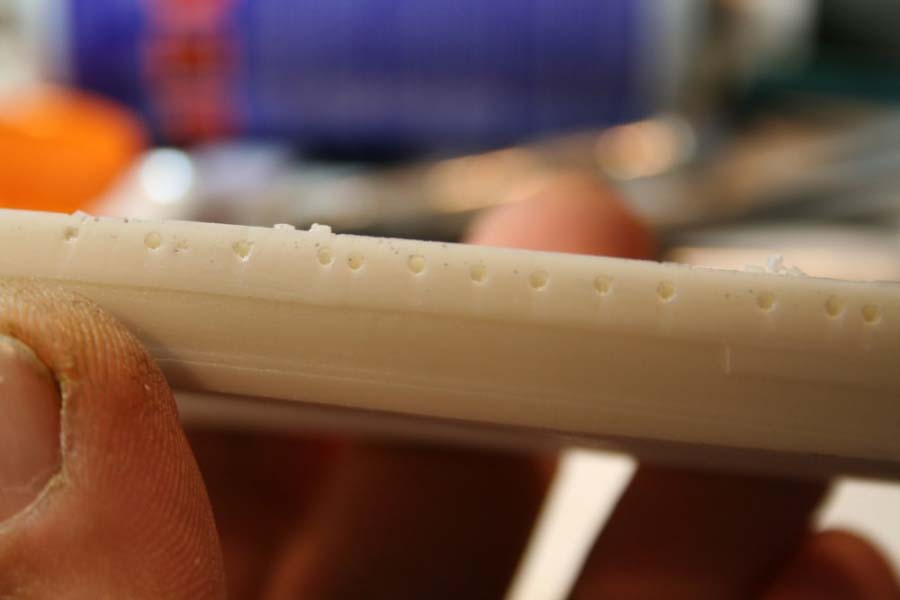
| The scuttles in the midships section of Romas hull have
hinged lids-these were closed when the ship is underway - although they
are often seen open when the ship is alongside.
The lids had a slightly convex shape outwardsearly experiments with small PE discs did not convey the correct impression to my eyes so I drilled all the ports lightly oversizeand inserted appropriate size plastic rod. Once this had hardened it was cut off with a chisel bladeand the hull given a light sandingthis rounded off the hard edges. |
 |
|||||||||||||||||||||||||||||||||||||||||||||||||||
 |
||||||||||||||||||||||||||||||||||||||||||||||||||||
|
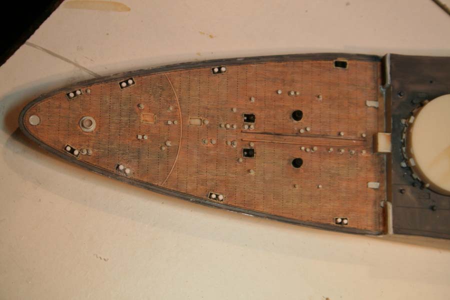
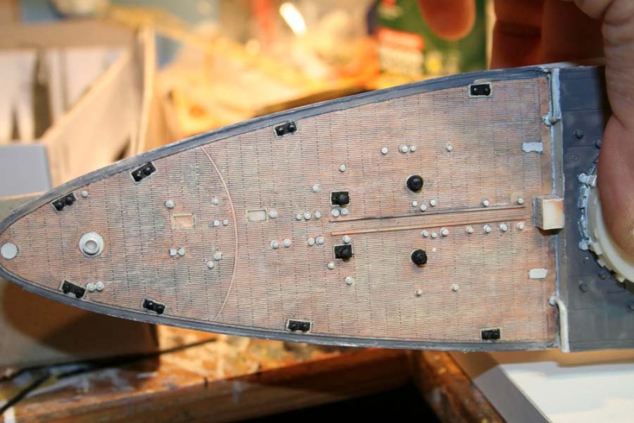
I next turned my attention to some preparatory work on the aft deck. I removed and replaced virtually all the cast on vents, and after early coats of paint and washing produced a deck, that whilst visually interesting was too intense for my liking. Some eyewitness accounts suggest that Romas deck planks had been caulked in a lighter colour than black pitch, some photos I had seen would support this. The deck casting featured the plank butt ends-which whilst a nice detail, were in my opinion too pronounced and thereby visually intrusive. With the benefit of hindsight I perhaps could have re-decked this area with a styrene deck . |
||||||||||||||||||||||||||||||||||||||||||||||||||||
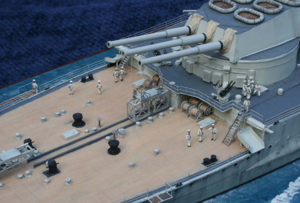
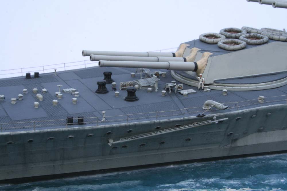
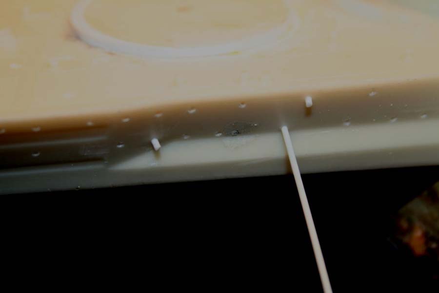
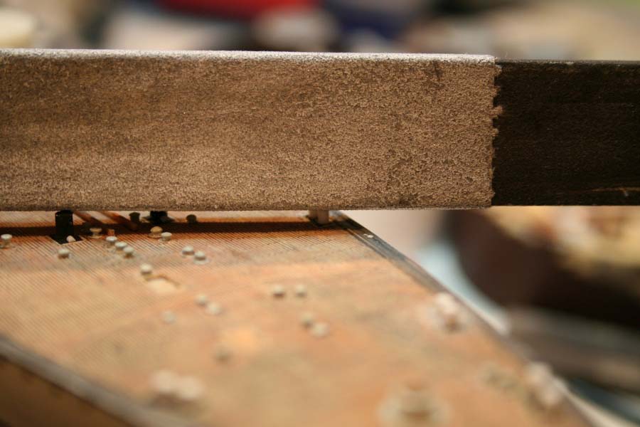
| I removed all the cast-on mooring bitts as some were damaged,
and then replaced them around the whole ship with styrene rods inserted
into pre-drilled holes.
The virtual impossibility of ensuring all drilled holes and the rods to be of uniform height led to the use a homemade coarse sanding stick to level them all out. |
 |
|||||||||||||||||||||||||||||||||||||||||||||||||||
 |
||||||||||||||||||||||||||||||||||||||||||||||||||||
| The Samson posts in the aft deck were drilled longitudinally and the small bars inserted, and thereafter was all painted black. | 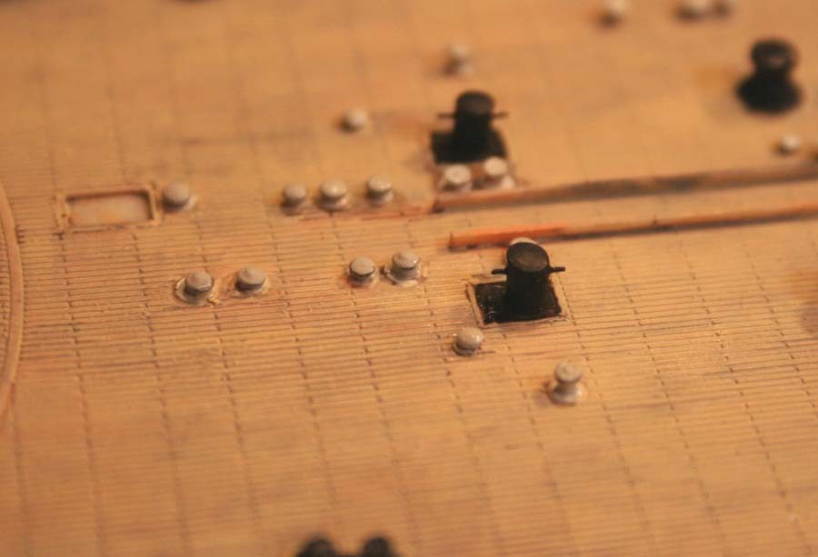 |
|||||||||||||||||||||||||||||||||||||||||||||||||||
 |
||||||||||||||||||||||||||||||||||||||||||||||||||||
|
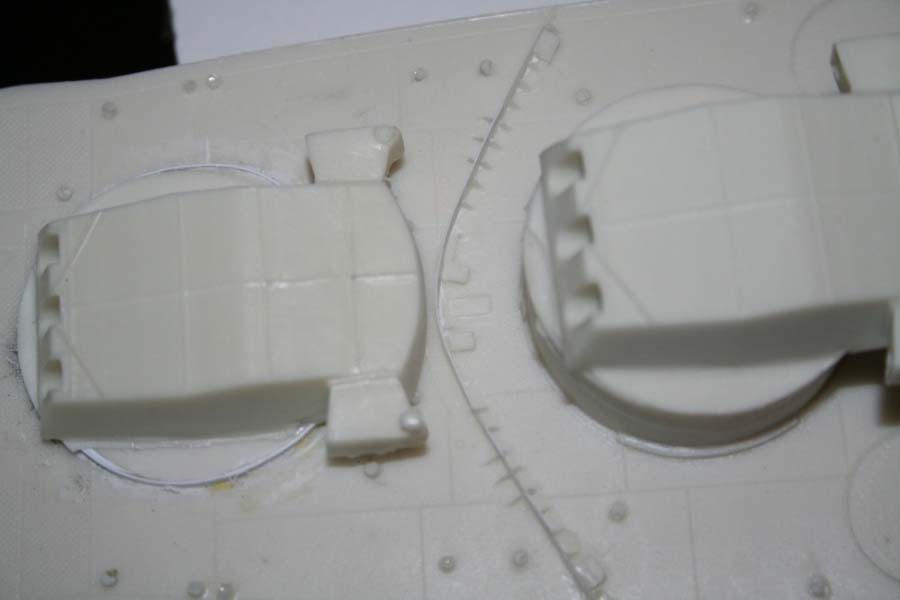
So as not to get bogged down in one area I often changed onto a different facet of the modeland hereby I replaced and repaired the barbette top plates, which were attached to the turret sides. The lower corners of the turretswhich protruded below the top plates were repaired and sharpened up with styrene strip inserted and sanded. At the same time I took the opportunity of replacing the damaged cast AA splinter shields with copper strip and wire (for the rolled edge as described earlier) |
 |
|||||||||||||||||||||||||||||||||||||||||||||||||||
 |
||||||||||||||||||||||||||||||||||||||||||||||||||||
 |
||||||||||||||||||||||||||||||||||||||||||||||||||||
 |
||||||||||||||||||||||||||||||||||||||||||||||||||||
|
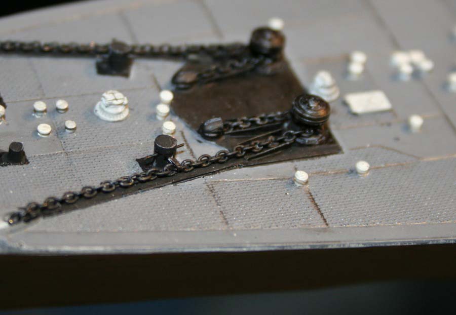
After drilling out the fwd hawse pipes I drilled the mooring bits again and inserted the thin fore and aft bars. Chain guides were of supplied PE, |
 |
|||||||||||||||||||||||||||||||||||||||||||||||||||
 |
||||||||||||||||||||||||||||||||||||||||||||||||||||
|
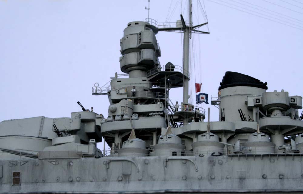
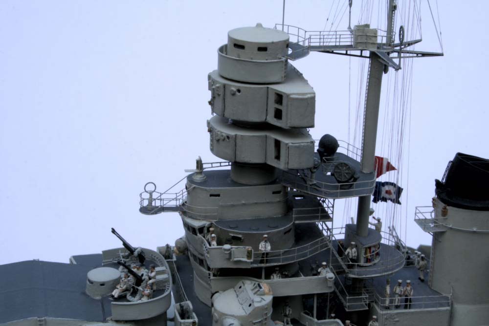
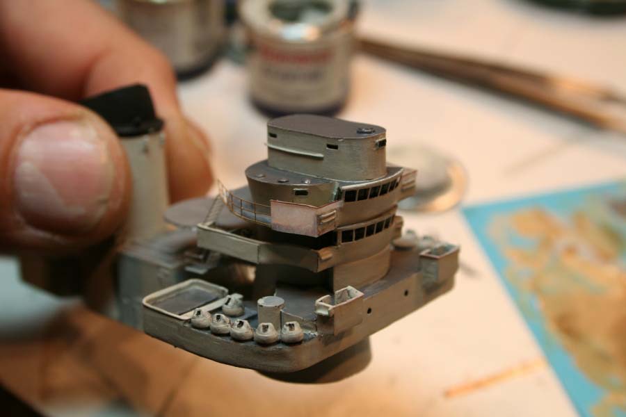
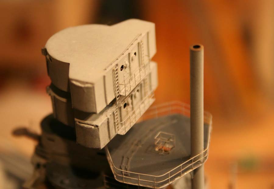
For a change of scene I turned my attention to the bridge structure. First of all I wanted to install the lovely looking shaped PE Bridge window frames. This was not quite as easy as it would have appeared at first sight. The PE window frames were the correct shape and heightthe aperture in the casting was too large Once again some diligent additions of fine microstrip and Mr Surfacer along with much sanding filled the gaps. |
 |
|||||||||||||||||||||||||||||||||||||||||||||||||||
 |
||||||||||||||||||||||||||||||||||||||||||||||||||||
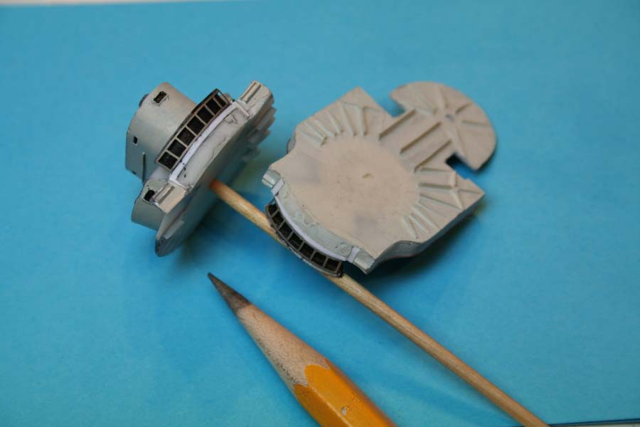
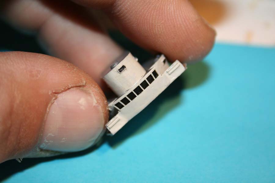
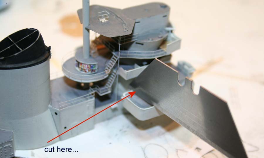
| The lower bridge assembly was dauntingI did not want at
this early stage to commit myself and glue all the levels yet, as there
were stairway platforms to install and it all needed to be checked and
re-checked. The flag platform was too long and needed to be shortened;
the photos should be self-explanatory.
A butt glue-join, new splintershields and PE gratings completed the job. |
 |
|||||||||||||||||||||||||||||||||||||||||||||||||||
 |
||||||||||||||||||||||||||||||||||||||||||||||||||||
 |
||||||||||||||||||||||||||||||||||||||||||||||||||||
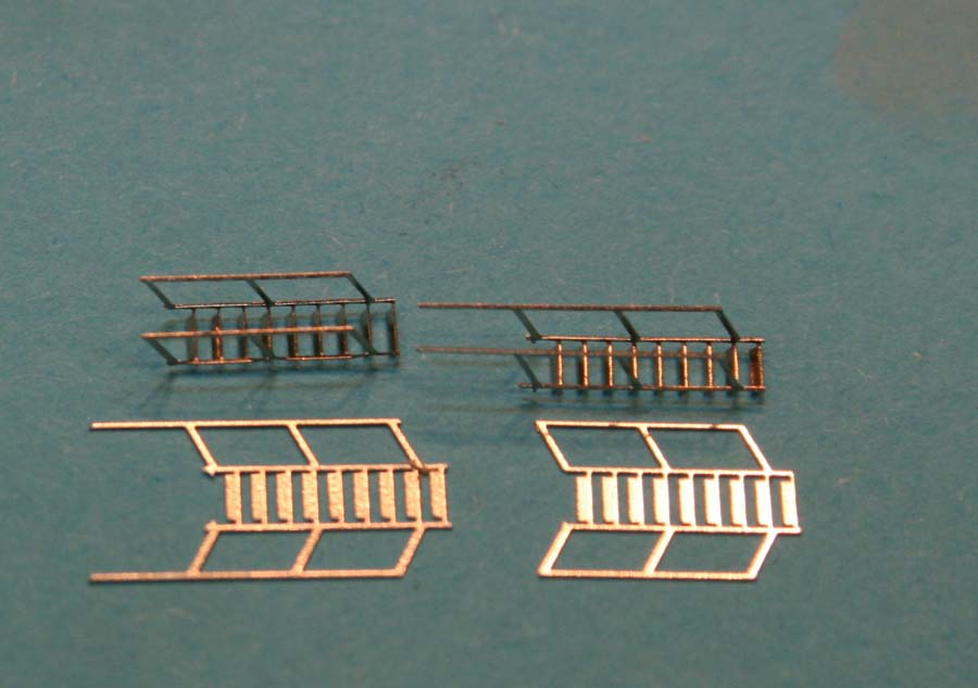
| The lower PE stairway platform also needed some modifications. | 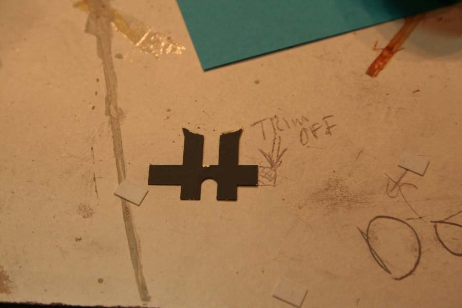 |
|||||||||||||||||||||||||||||||||||||||||||||||||||
 |
||||||||||||||||||||||||||||||||||||||||||||||||||||
|
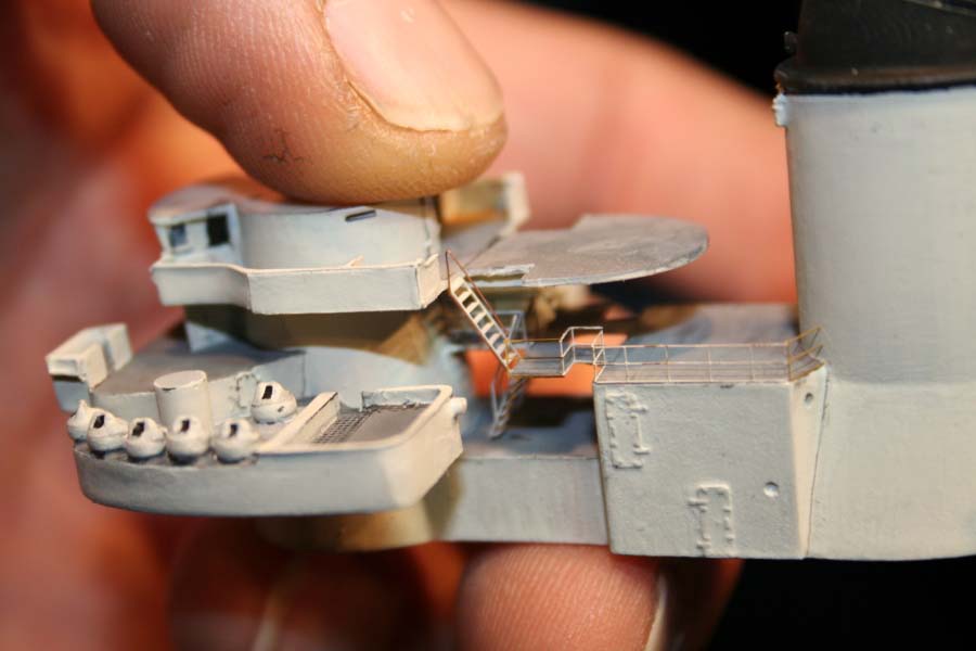
The use of styrene strips to establish their lengths and angles was very useful prior to making the stairs themselves. I also eschewed the PE stair handrails for some finer copperwire versions of my own makingwhich also had only on baras gleaned from a photo! |
 |
|||||||||||||||||||||||||||||||||||||||||||||||||||
 |
||||||||||||||||||||||||||||||||||||||||||||||||||||
 |
||||||||||||||||||||||||||||||||||||||||||||||||||||
|
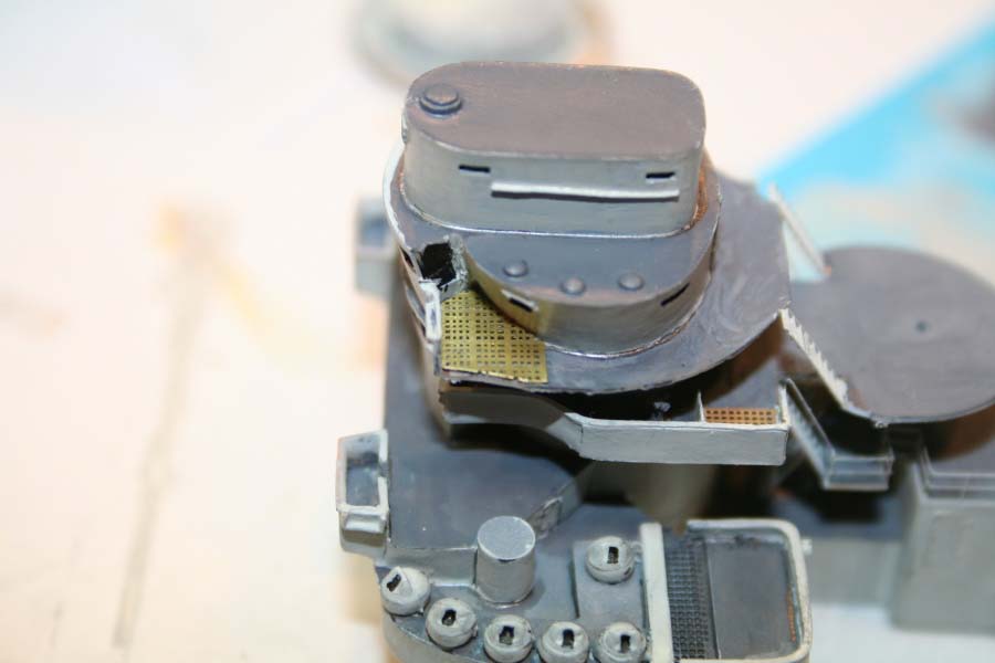
The upper levels again benefited extensively from the use of styrene mock-ups to establish reach and angle-which highlighted the necessity of adding a filler to the flag deck fwd stair aperture edge |
 |
|||||||||||||||||||||||||||||||||||||||||||||||||||
 |
||||||||||||||||||||||||||||||||||||||||||||||||||||
|
Paper patterns were made for the replacement gratings of scrap PE to match the new, sharper items one deck down. The paper patterns were the applied to the PE with double sided tape and cut using scissors |
 |
|||||||||||||||||||||||||||||||||||||||||||||||||||
 |
||||||||||||||||||||||||||||||||||||||||||||||||||||
|
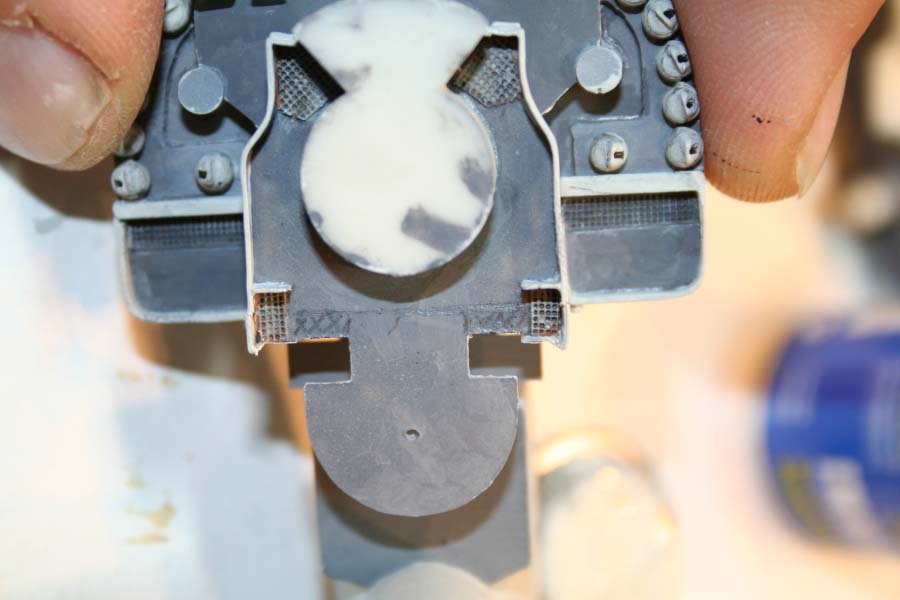
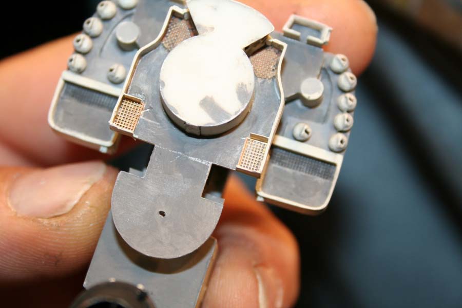
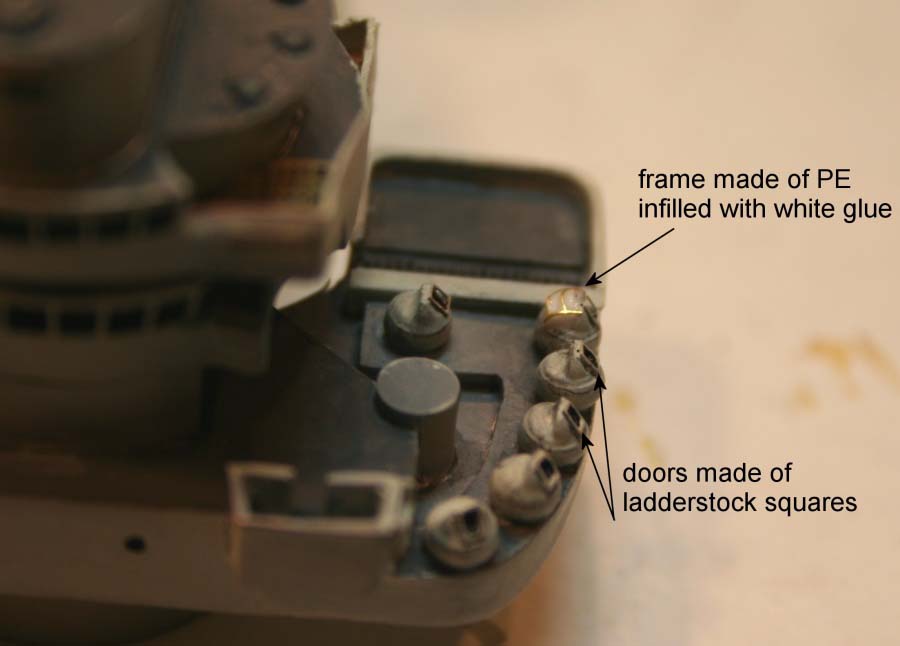
Having fitted the stairs from Flag deck up I then encountered a small asymmetry in the next level upI cured this by making a wire frame of the correct shape and infilling with white glue- which fortunately self-levels. The above procedure necessitated replacement (taller) splintershields in paper |
 |
|||||||||||||||||||||||||||||||||||||||||||||||||||
 |
||||||||||||||||||||||||||||||||||||||||||||||||||||
| Meanwhile many of the cast platform gusset supports had been crushed during the repeated test-fittingsI therefore elected to replace virtually all by making paper gussets tacked on with white glue and the infused with CA | 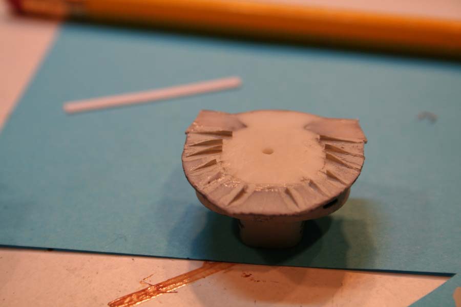 |
|||||||||||||||||||||||||||||||||||||||||||||||||||
|
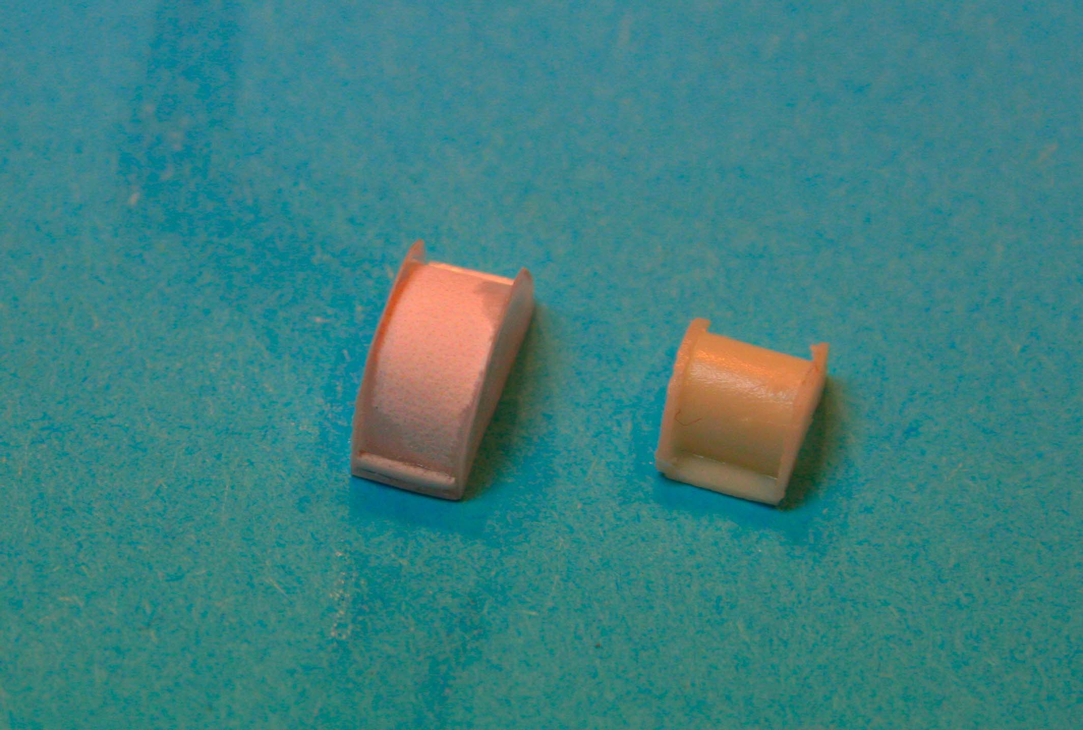
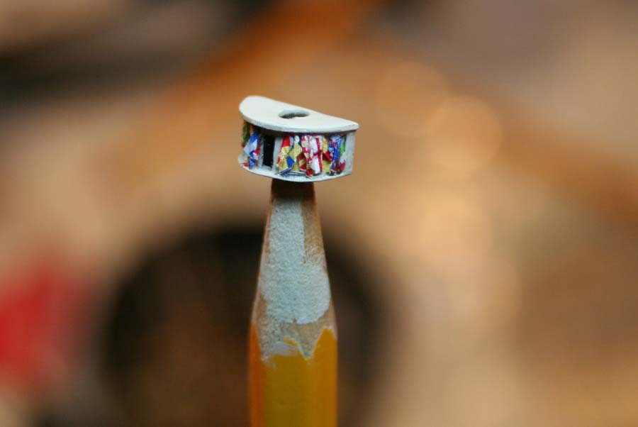
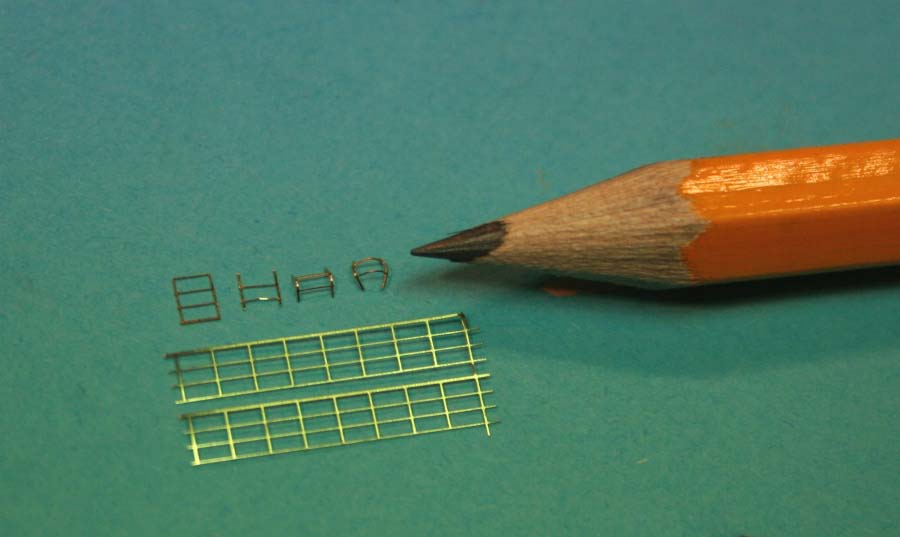
On the flag deck sat the flag locker. The cast resin item appeared to be undersizeand would not allow the internal detailing of the structure and hanging in the signal flags. I made an entirely new item of paper, as ever infused with CA for rigidity |
 |
|||||||||||||||||||||||||||||||||||||||||||||||||||
 |
||||||||||||||||||||||||||||||||||||||||||||||||||||
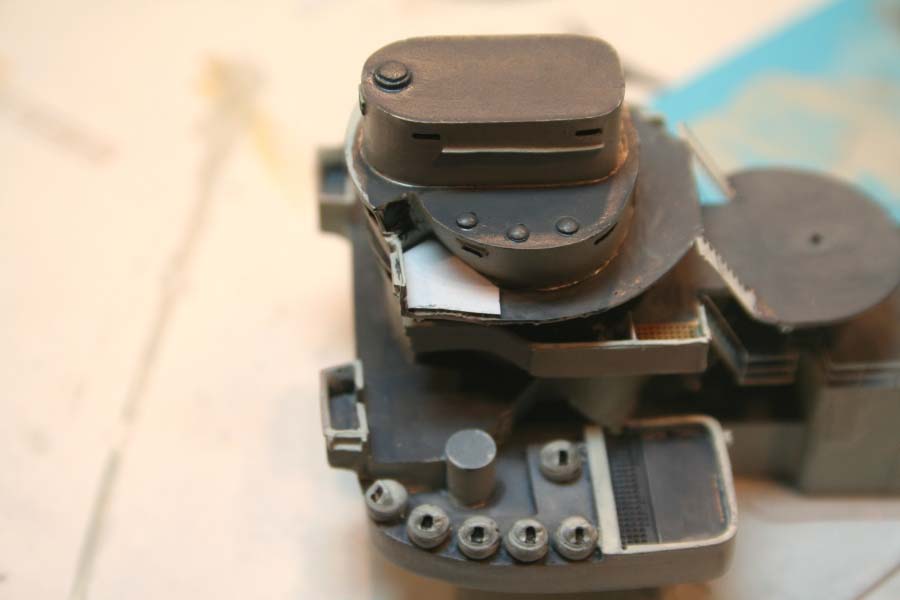
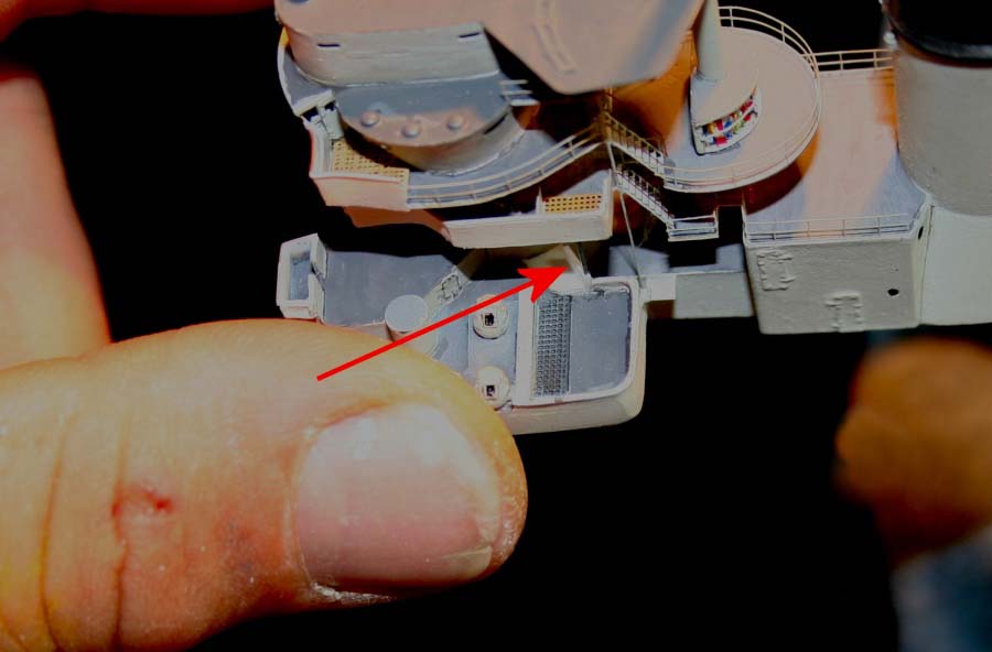
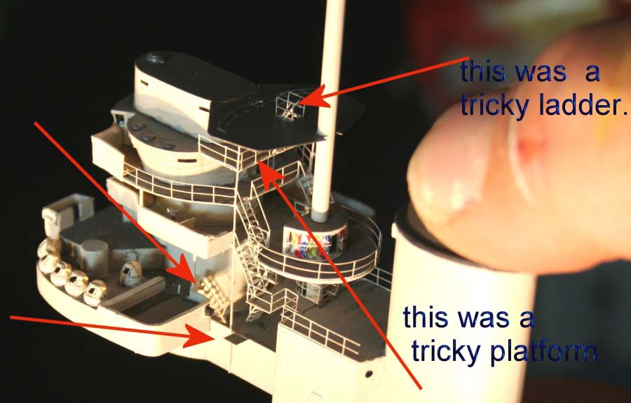
| Whilst assembling the bridge tower structure, checking
and rechecking the outline and height against the drawings, photos and
images of the Barbieri model I noticed a discrepancy in the outline of
the lower platform, which did not allow the staircase to reach.
I added the missing sections using styrene sheet inserts made from previous paper patterns. This also required the bulwark to be cutto allow a support to sit on the intersecting angle |
 |
|||||||||||||||||||||||||||||||||||||||||||||||||||
 |
||||||||||||||||||||||||||||||||||||||||||||||||||||
 |
||||||||||||||||||||||||||||||||||||||||||||||||||||
| The uppermost platform was supplied as a commendably thin
PE part-and fitted beautifully!
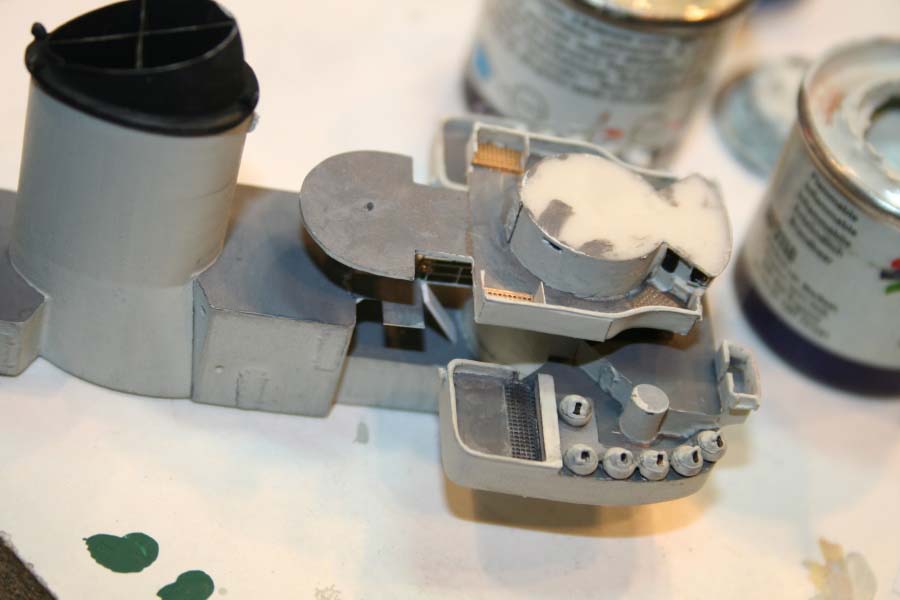
The lower range sighting monopods clustered around the lower bridge area had a folding canvas rood. The kit parts made no provision for theseso I made a small hood frame of WEM PE close spaced handrails, curved to shape and in-filled with white glue to simulate the hollowing of tensioned canvas between frames. |
 |
|||||||||||||||||||||||||||||||||||||||||||||||||||
 |
||||||||||||||||||||||||||||||||||||||||||||||||||||
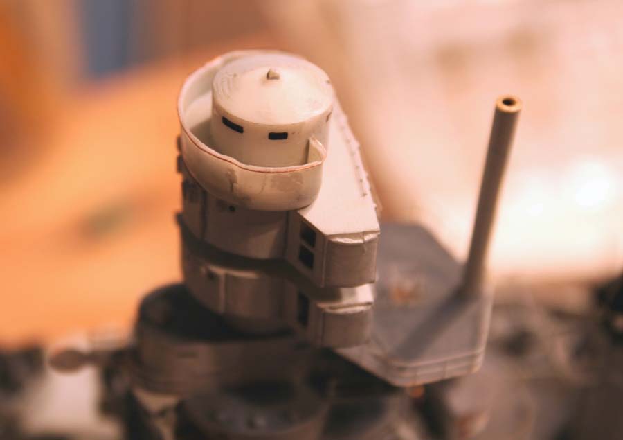
| The larger fwd rangefinders also had small canvas hoodsmade in a similar manner along with a number of other subtle modificationsas well as improving the surface finish. The walkway was supplied as a PE part. | 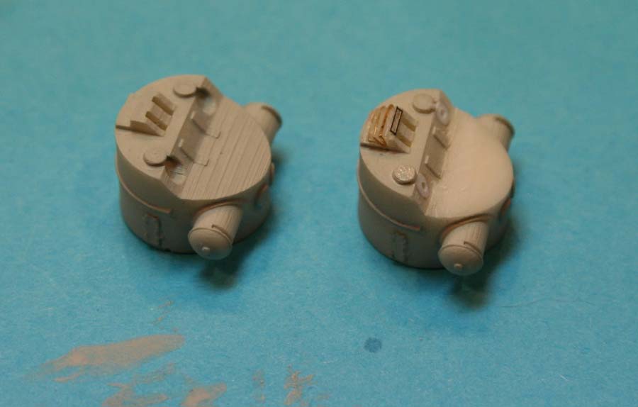
 |
|||||||||||||||||||||||||||||||||||||||||||||||||||
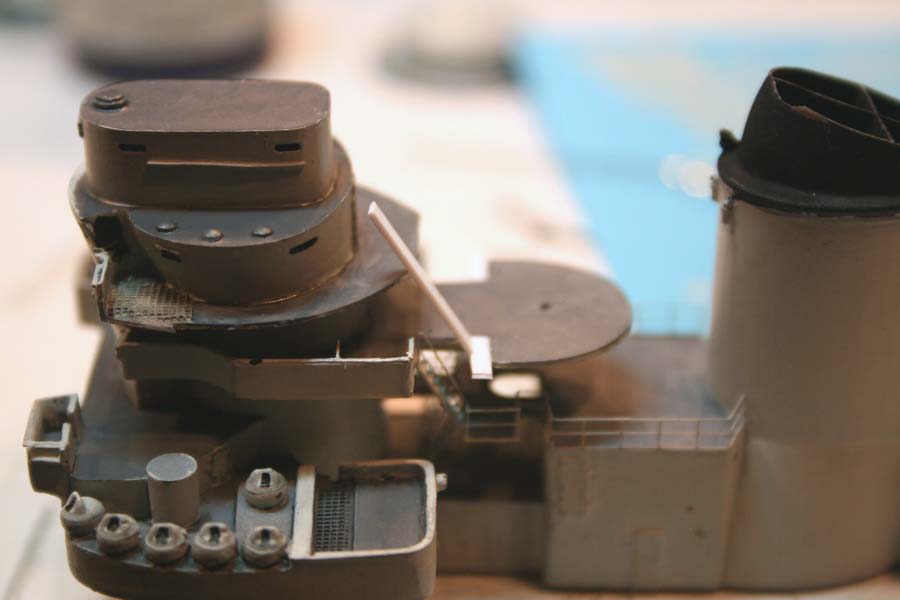
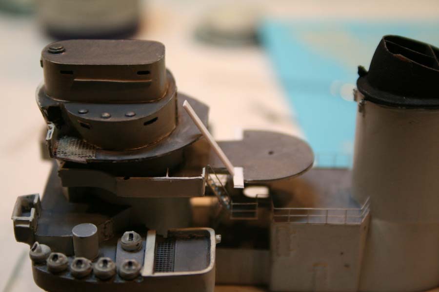
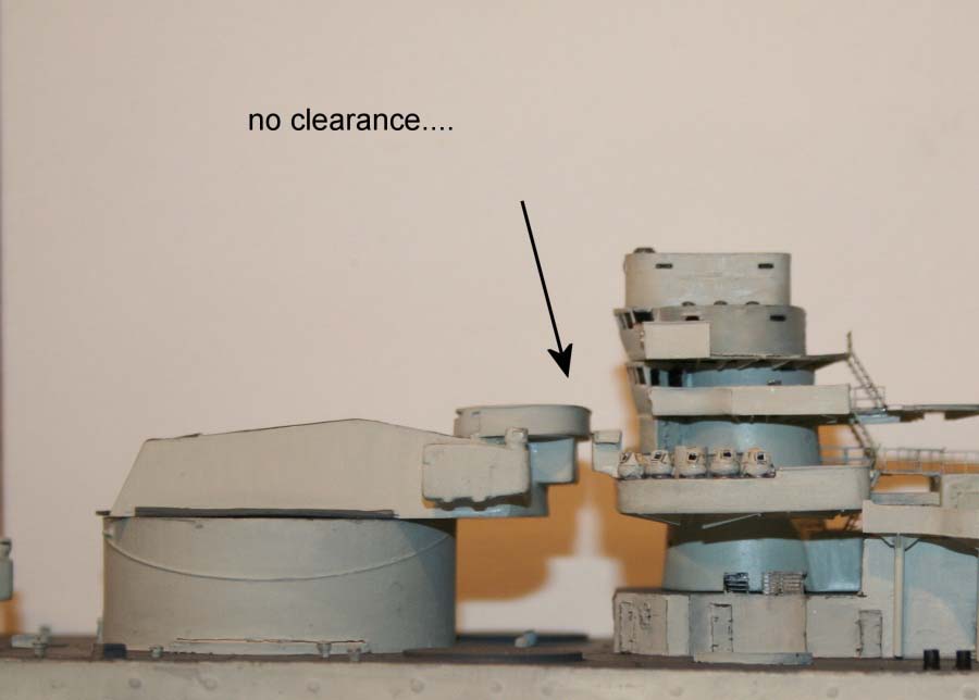
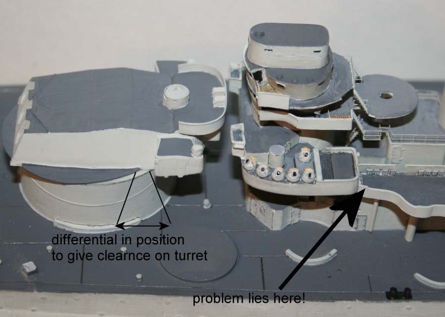
| Further test fitting of the bridge structure in relation
to the B turret showed there to be a dimensional discrepancy
The AA platforms-whose positions were governed by the position of the supporting legswhich were in the correct place- forced the bridge tower to be too far forward-to the extent that B-turrets AA platform had no clearance to rotate relative to the bridge assembly. Extensive measuring of plans versus the model with a digital calliper showed the fwd end of the platforms to be too long. Trimming these backand making a (thin) paper bulkhead allowed the tower to move aft to its correct position |
 |
|||||||||||||||||||||||||||||||||||||||||||||||||||
 |
||||||||||||||||||||||||||||||||||||||||||||||||||||
 |
||||||||||||||||||||||||||||||||||||||||||||||||||||
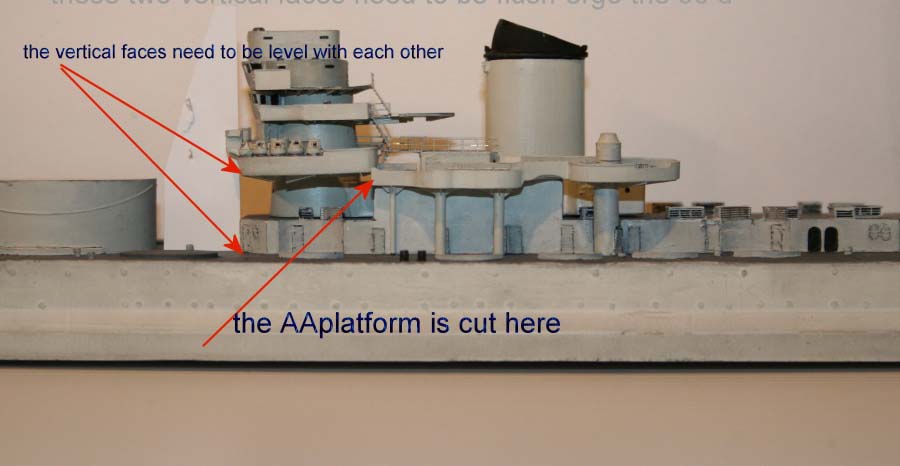
| I also noticed a gentle bit of curvature to the lower part
of the funnel trunk casting; whilst I was able to bend it straight with
the application of finger pressure I was unable to straighten it permanently.
As the lower bridge tower and the fwd funnel would not be square relative to each otherand distrustful of a glue joint or indeed my ability of keeping sufficient pressure upon the parts whilst glue set I chose a mechanical solution-- Self tapping No 8 screws in countersunk holes permitted both the straightening of the casting as well as fine-tuning the vertical parts independently |
 |
|||||||||||||||||||||||||||||||||||||||||||||||||||
 |
||||||||||||||||||||||||||||||||||||||||||||||||||||
| Once these final positions had been settled upon, it was desirable to complete as much of the work on the bridge off the hullas this allowed access to the undersides of the platforms for the aforementioned platform supporting gusset repairs, as well as permitting the accurate placing of the vertical inter-deck-connecting columns | 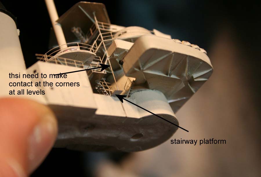 |
|||||||||||||||||||||||||||||||||||||||||||||||||||
 |
||||||||||||||||||||||||||||||||||||||||||||||||||||
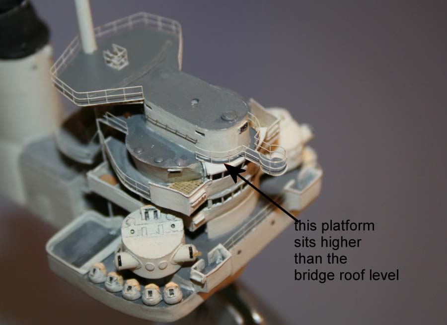
| The bridge tower, in all its complexity was beginning to take shapeand
I was able to move on towards some of the finer detailing work.
Study of plans showed the platform above the upper row of bridge windows to be raised above the bridge roof level. I simulated this by projecting the railing at the same level as the neat supplied PE platform, and then infilling the resultant gap with white glue. The effect is quite convincing! |
 |
|||||||||||||||||||||||||||||||||||||||||||||||||||
|
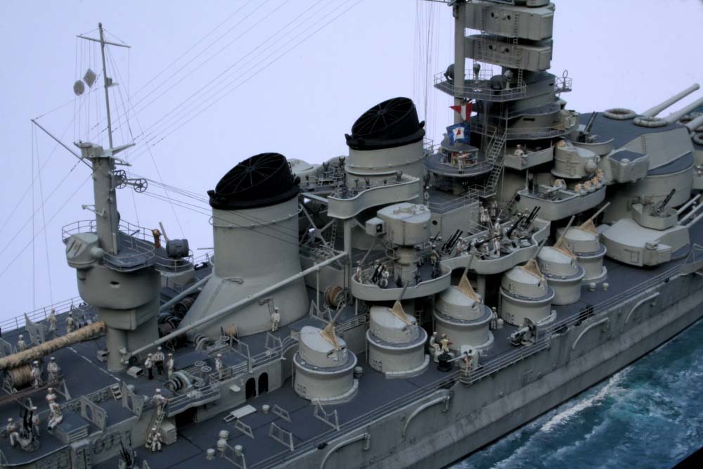
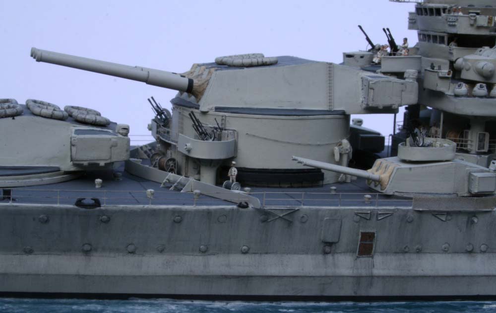
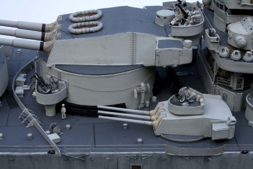
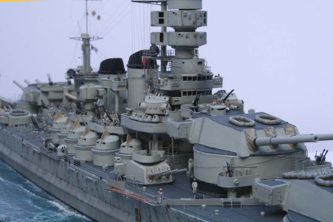
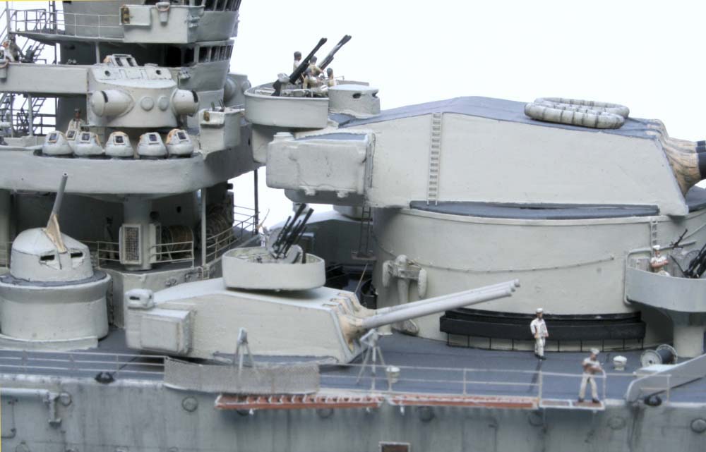
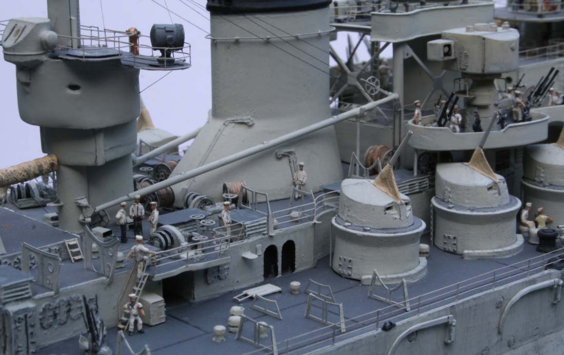
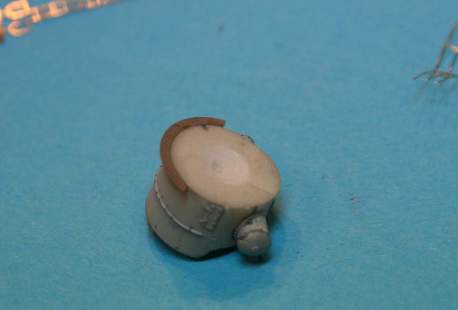
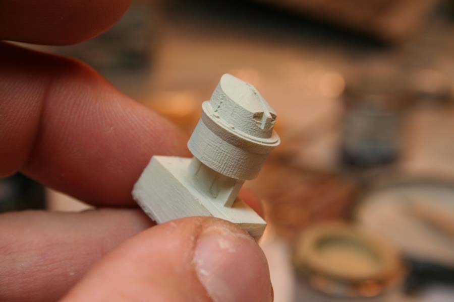
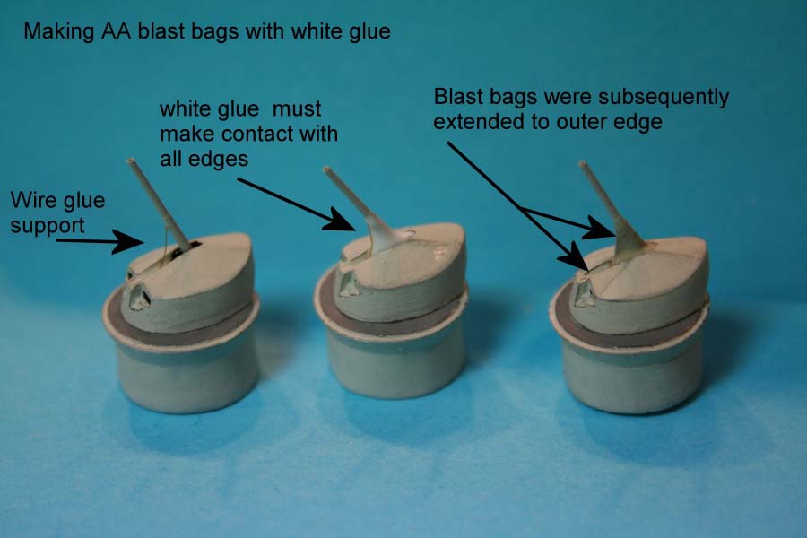
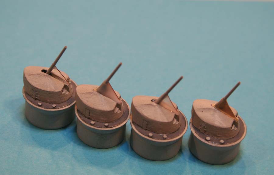
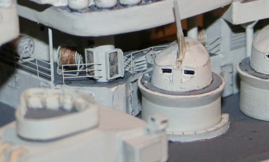
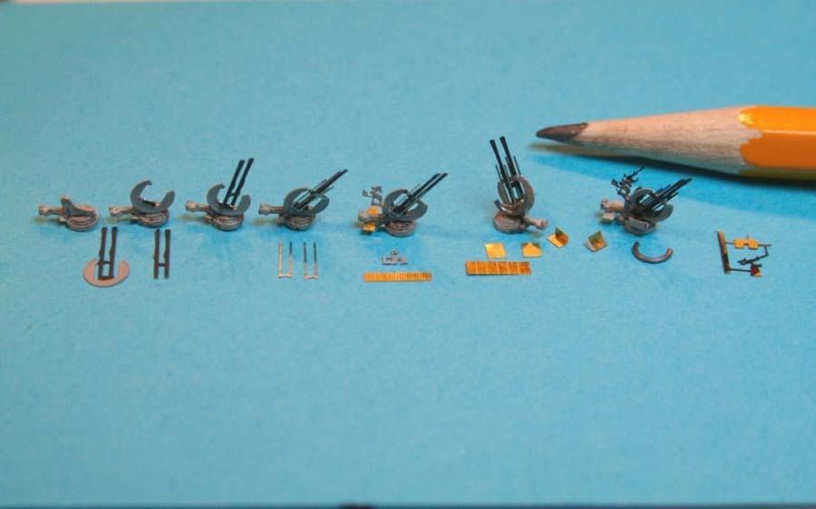
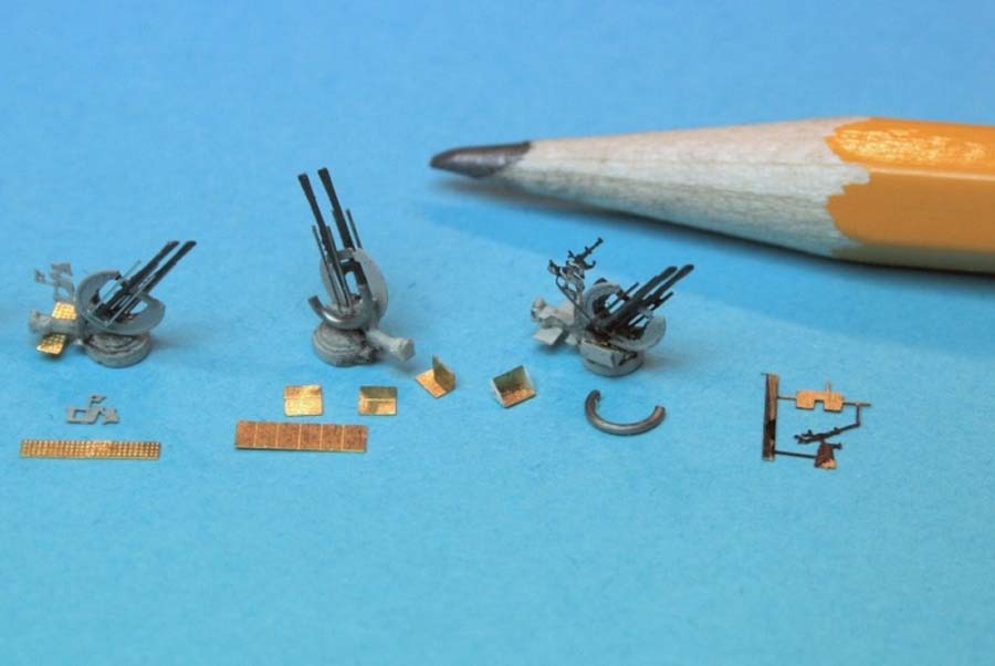
The High-Angle AA gun turrets were nicely shapedbut in my issue of the kit the surface finish of the casting was not of the best quality. After extensive sanding and paring with a blade I inserted brass barrels ( 1/700 USN 8 in Mk12 from the Japanese Incomparable Series- item 1206) I fashioned the distinctive blastbags using white glue spanned from the barrel to a wire support at the outer edge I initially based my blastbag shapes on a superb close-up photo of a sistership to Roma later, when I came across a better photo of Roma herself, I noticed a difference in the outboard attachment of the blastbag-and had the dubious pleasure of altering all 16 turrets to suit. |
 |
|||||||||||||||||||||||||||||||||||||||||||||||||||
 |
||||||||||||||||||||||||||||||||||||||||||||||||||||
 |
||||||||||||||||||||||||||||||||||||||||||||||||||||
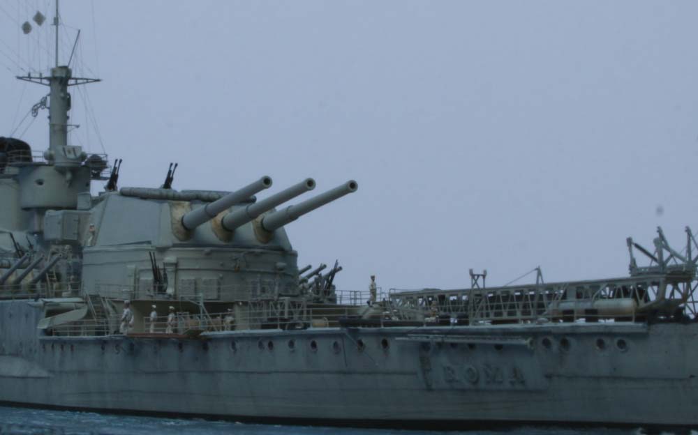
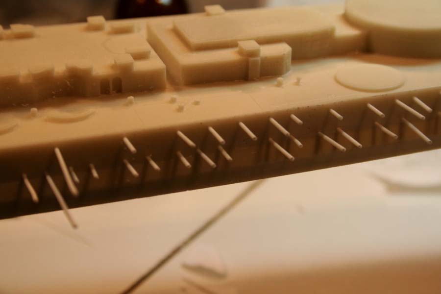
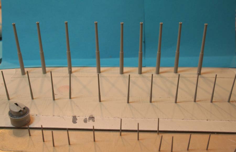
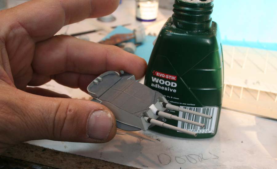
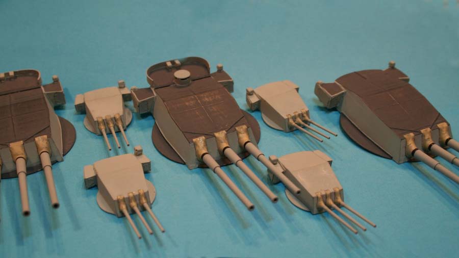
| At this stage-as a diversion from matters of the bridge,
I decided to turn my attention the main and secondary armament.
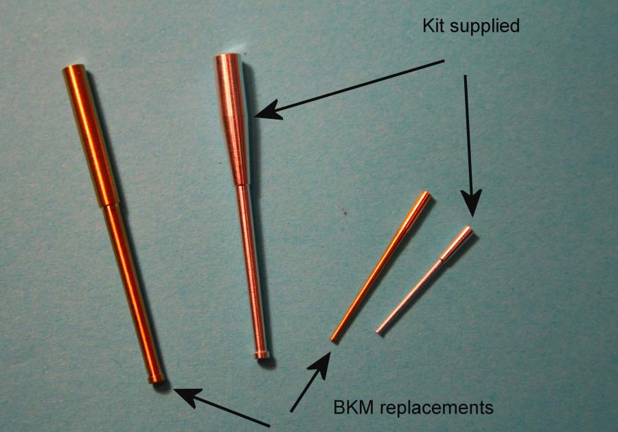
I was never entirely happy with the pronounced taper shape of the kit-supplied main and secondary gunsand I also felt the muzzle lip to be too pronounced. I therefore ordered a set of custom barrels from BKM in Germany. All the barrels were airbrushed in one fell swoop by sticking them muzzle-up on double-sided sticky tape. |
 |
|||||||||||||||||||||||||||||||||||||||||||||||||||
 |
||||||||||||||||||||||||||||||||||||||||||||||||||||
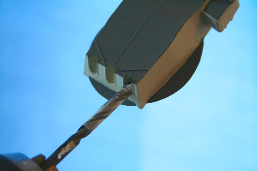
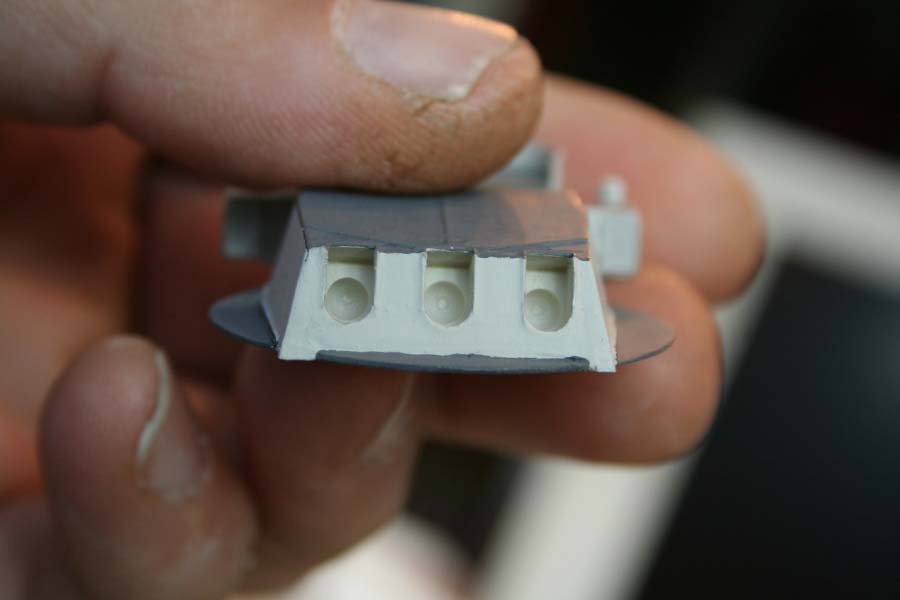
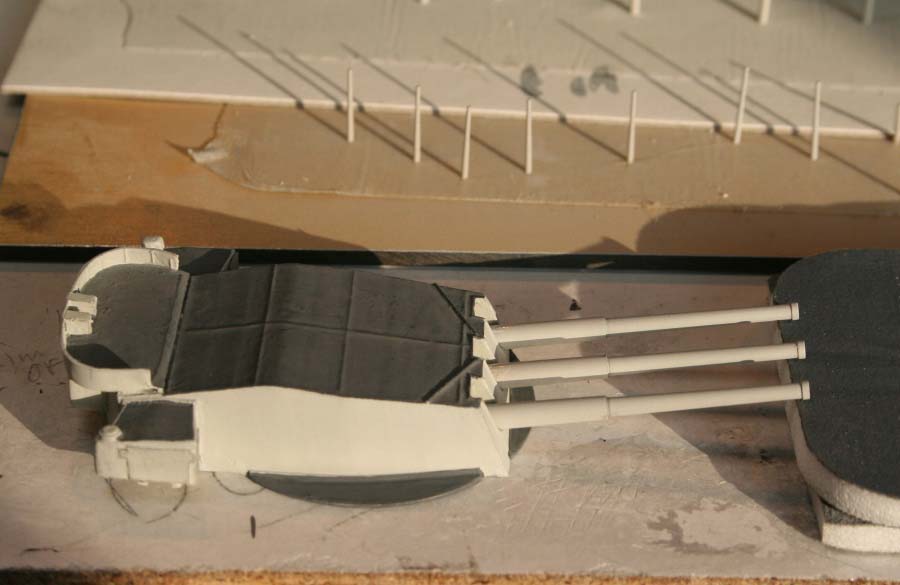
| The placement of these barrels necessitated drilling a
deep hole into the turret with a distance limiter of the on the drill bit.
Even elevation of the triple barrels was assured by the use of a simple
jig of sanding pads.
The distinctive blastbags were made of repeated applications of white glue, a painstaking but ultimately satisfying process. |
 |
|||||||||||||||||||||||||||||||||||||||||||||||||||
 |
||||||||||||||||||||||||||||||||||||||||||||||||||||
 |
||||||||||||||||||||||||||||||||||||||||||||||||||||
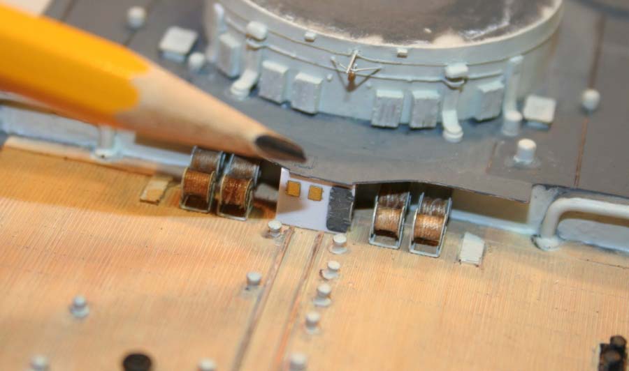
| As a diversionary measure at various times I made up the numerous cable reels required. The PE frets supplied the side wheels of various sizes and patternsas well as the supporting legs. The centre of the drums were made of styrene tubes which were wrapped with tan thread, soaked in CA glue and cut to the appropriate width required. | 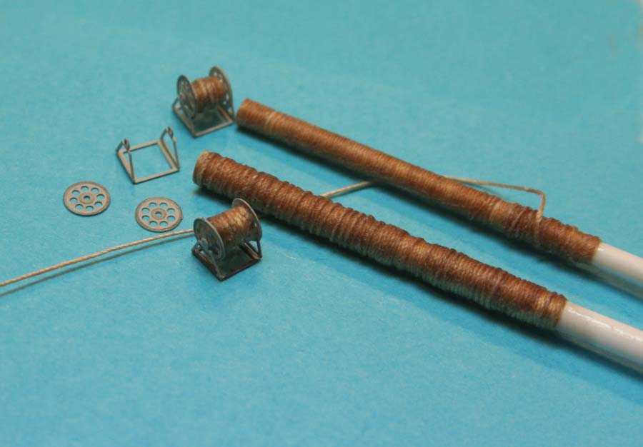 |
|||||||||||||||||||||||||||||||||||||||||||||||||||
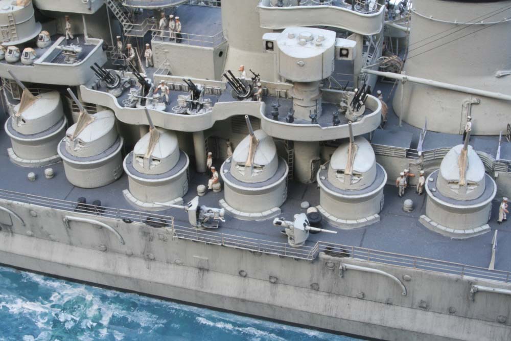
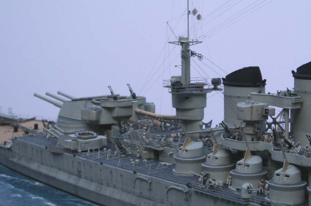
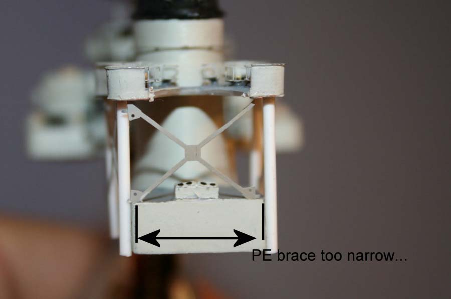
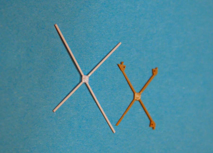
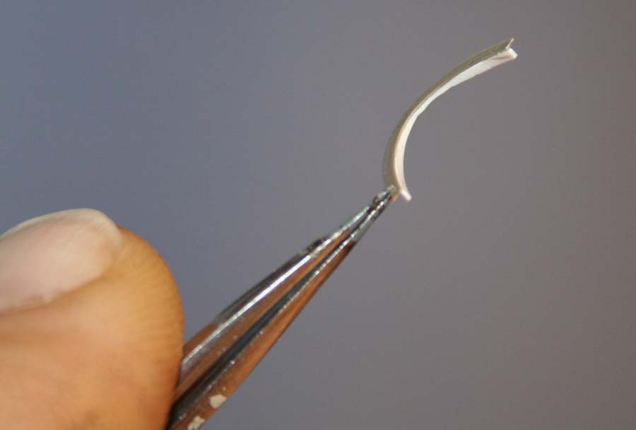
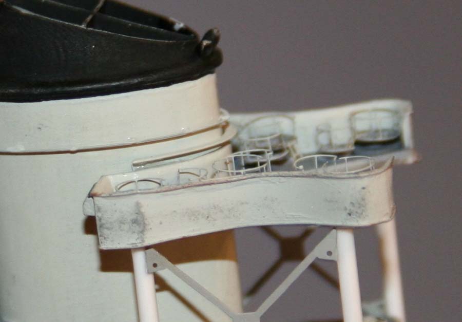
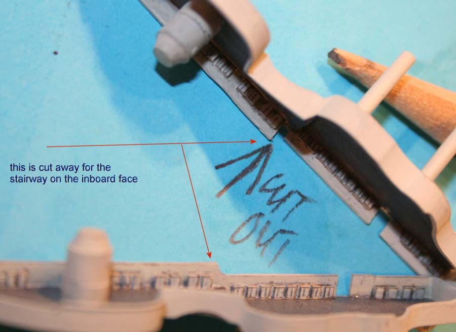
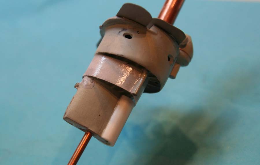
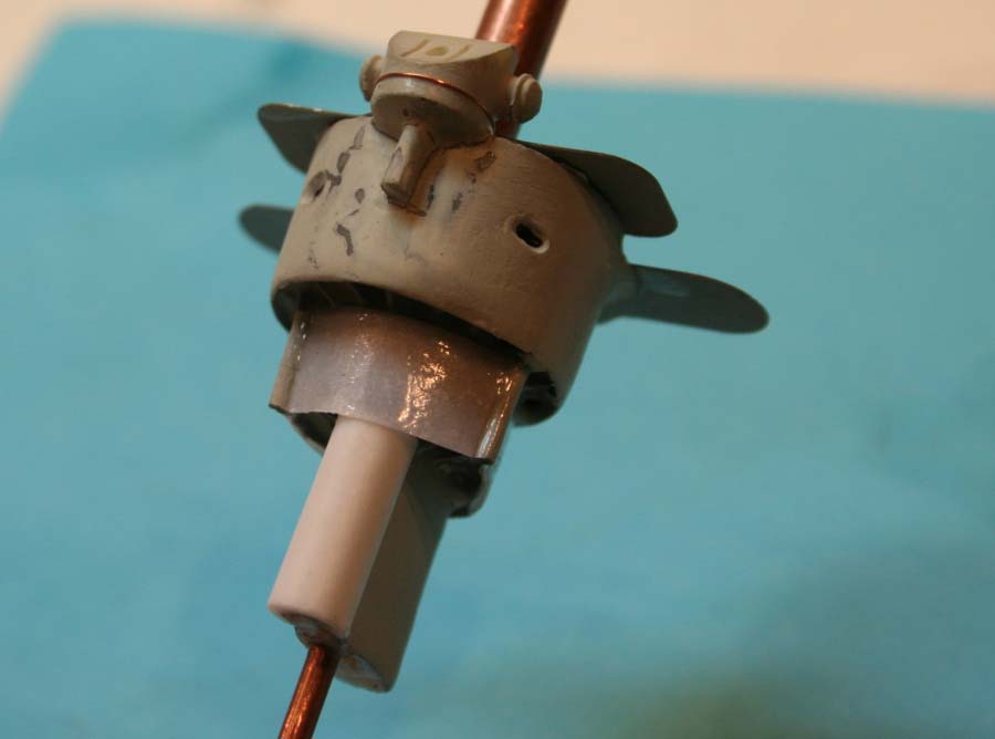
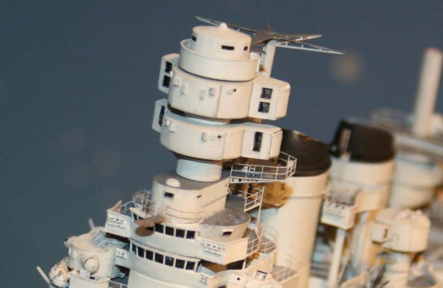
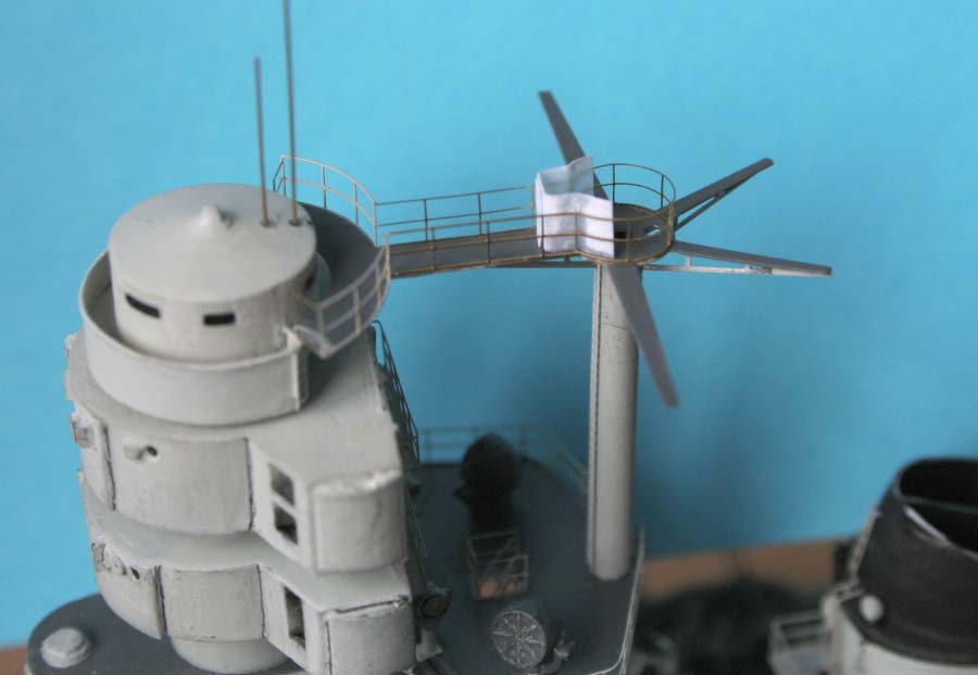
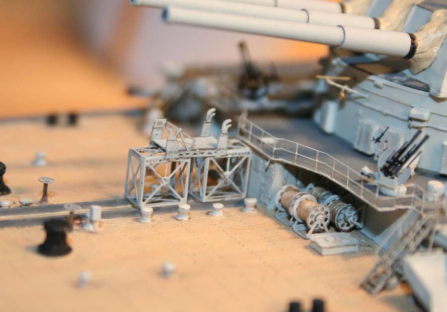
| The platform aft of the rear funnel which I had previously
added the wire to in order to simulate the curved top splinter shields
had the various rotating platforms added which were very nicely rendered
relief etched parts. I then added the railings from an old 1/500 setthe
height seemed much better proportioned. The platform was supported on 4
tall columns-which were braced with neat looking diagonal struts from the
PE fret. The braces worked fine on the sides but were far too narrow aft.
A new set was made of styrene strip with a paper bracing plate. I cut off the PE end braces and affixed them to my replacement bracing once installed At a later stage I added to the rotating platforms small ladder pieces, the equipment that sat upon them was scratchbuilt of brass and styrene bits - the purpose of the equipment I am still uncertain of - I was here guided by the items on the Barbieri model. |
 |
|||||||||||||||||||||||||||||||||||||||||||||||||||
 |
||||||||||||||||||||||||||||||||||||||||||||||||||||
 |
||||||||||||||||||||||||||||||||||||||||||||||||||||
|
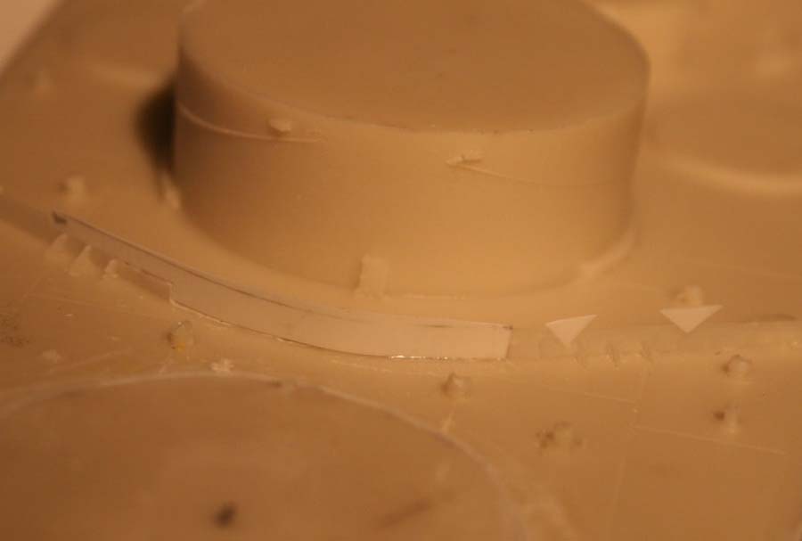
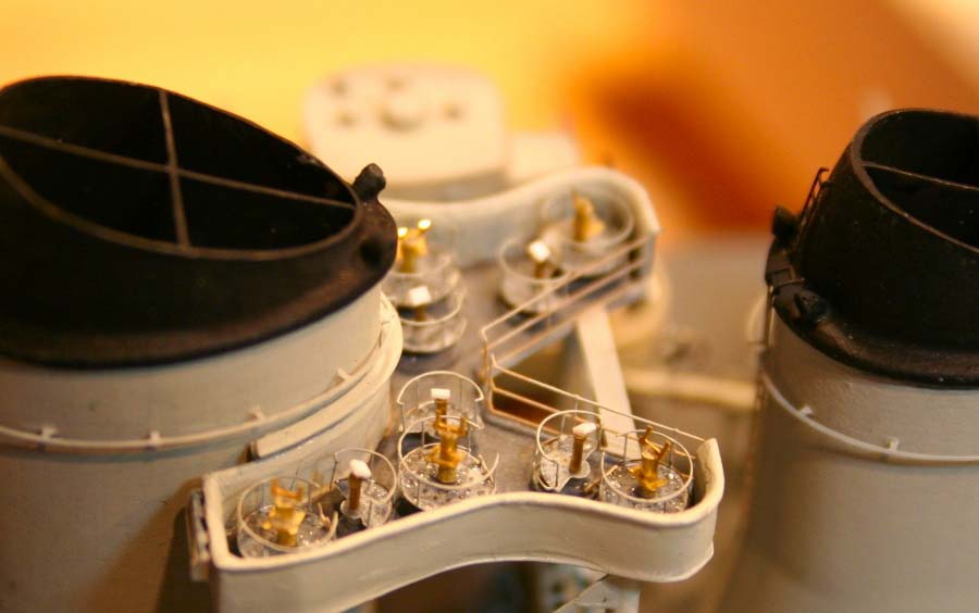
The forward edge of this platform where it abutted the aft funnel had a small circular platform-a very nice PE piece, however it needed to be supported somewhat higher than the splinter shield and the small gap needed to be filled. To this end I added a shim of styrene to the underside of the platform, tapered at the ends and carefully shaped in the centre so that it would fill the gap, raise the platform and be virtually invisible Meanwhile the funnels had been fitted with the PE handrails-in retrospect I perhaps should have made these myself, as a more delicate rail would have resulted. Additional vents were added fore and aft to the upper rim, and the fore funnel Siren platform fabricated from PE scrap, taking care to cut the ladder aperture before installation. |
 |
|||||||||||||||||||||||||||||||||||||||||||||||||||
 |
||||||||||||||||||||||||||||||||||||||||||||||||||||
 |
||||||||||||||||||||||||||||||||||||||||||||||||||||
|
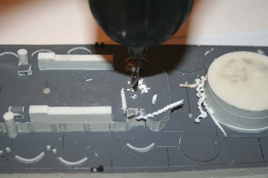
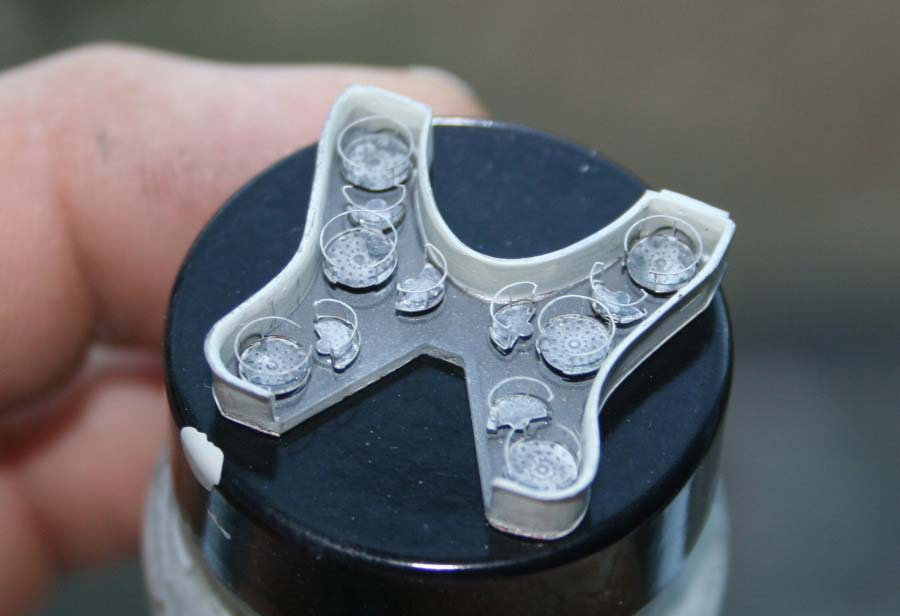
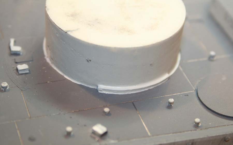
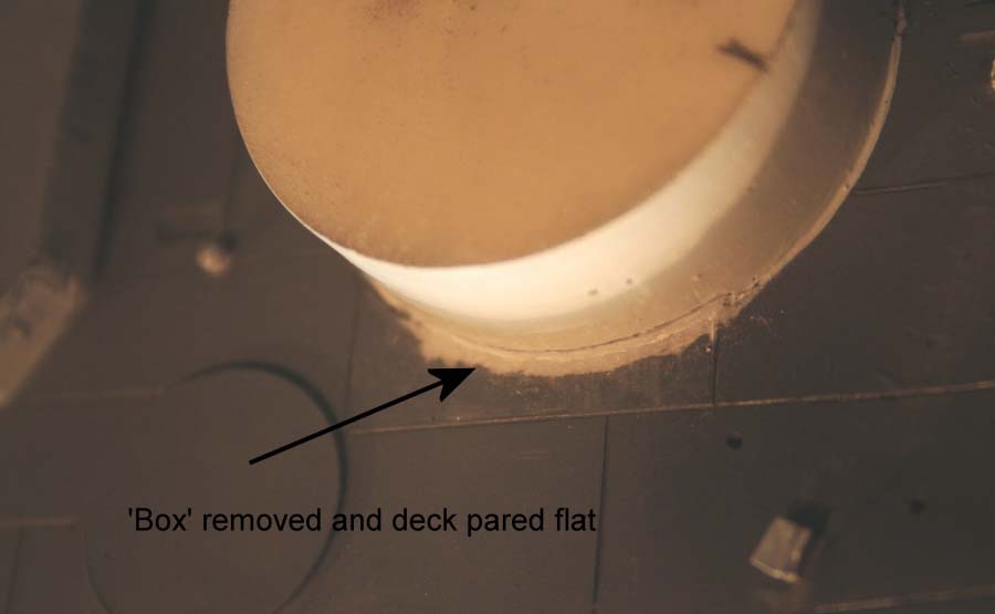
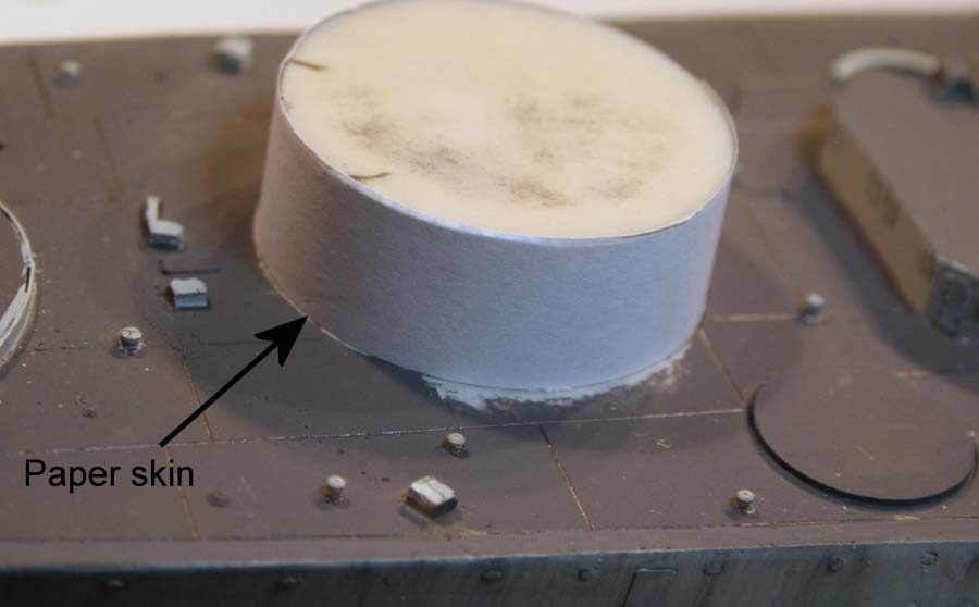
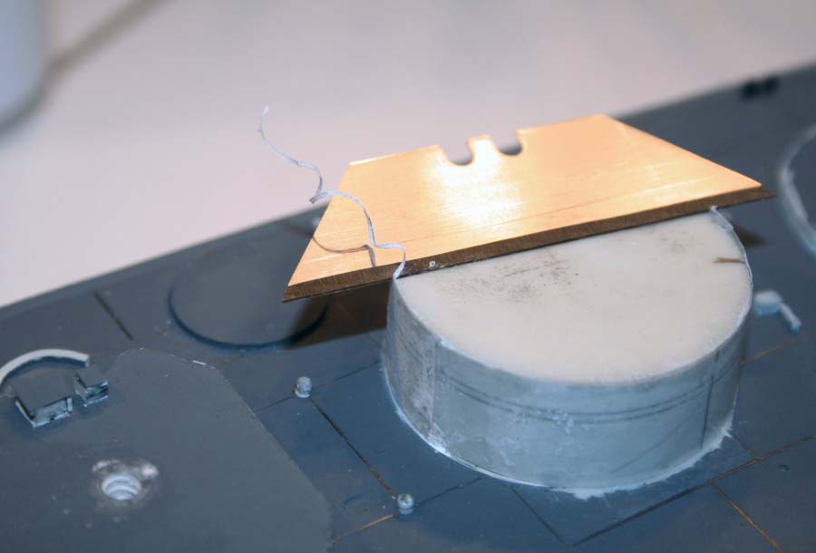
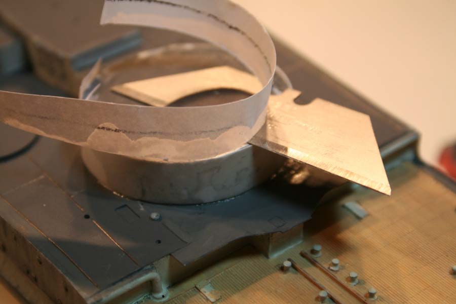
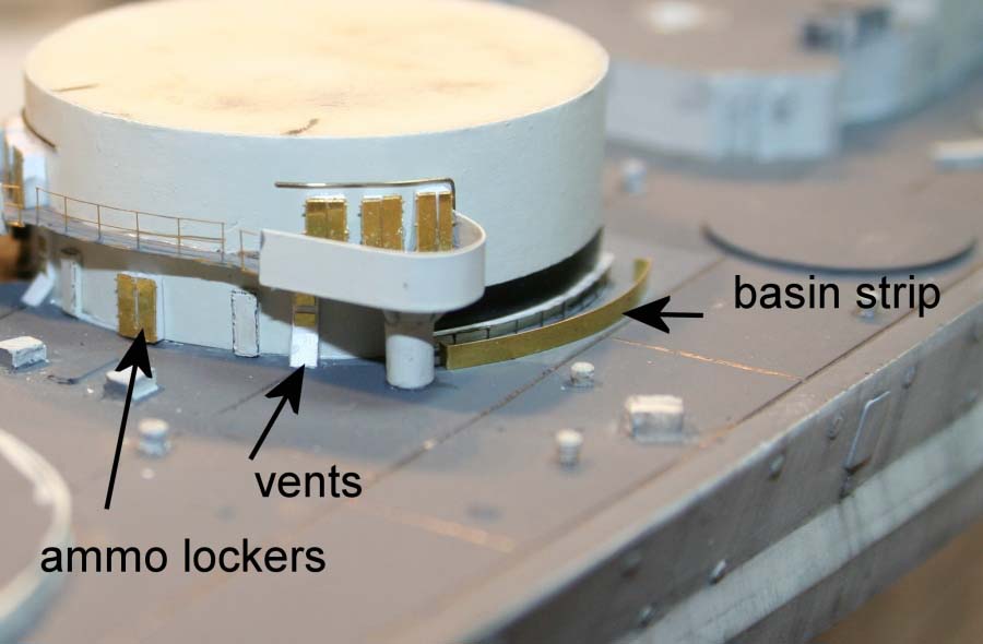
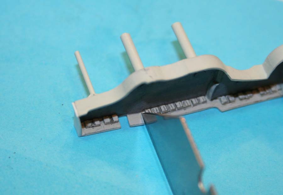
Back to main deck and the Barbette detail was no longer as fine as I wanted. I firstly removed the cast handrail and all cast on detail. At the base of the barbette was a box; close examination of photos and the Barbieri model showed these to be rows of washing basins the construction of which I will detail shortly. After these cutting operations the barbette was looking decidedly shabbyand not wanting to attempt to fill and fair a barbette cast onto the hull I was faced with either complete removal and re-fabrication or resurfacing. This latter course I chose- I skinned the two raised barbettes with paper, join placed at the aft dead centre where the turret overhang would conceal it most effectively. I applied the paper oversize and tacked it in place with a small spot of white glueand then infused the paper with CA. Once set with some Kicker spray I then trimmed off the excess with a sharp blade. |
 |
|||||||||||||||||||||||||||||||||||||||||||||||||||
 |
||||||||||||||||||||||||||||||||||||||||||||||||||||
 |
||||||||||||||||||||||||||||||||||||||||||||||||||||
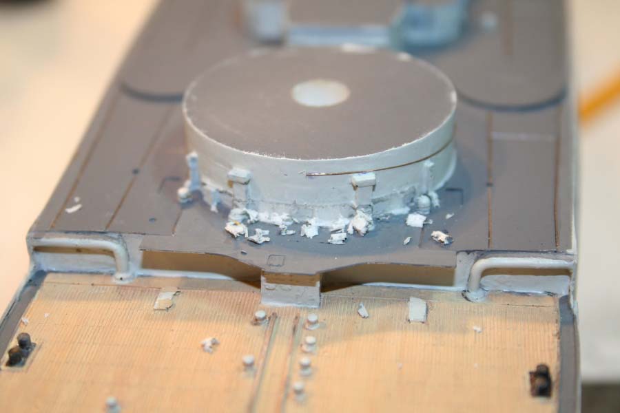
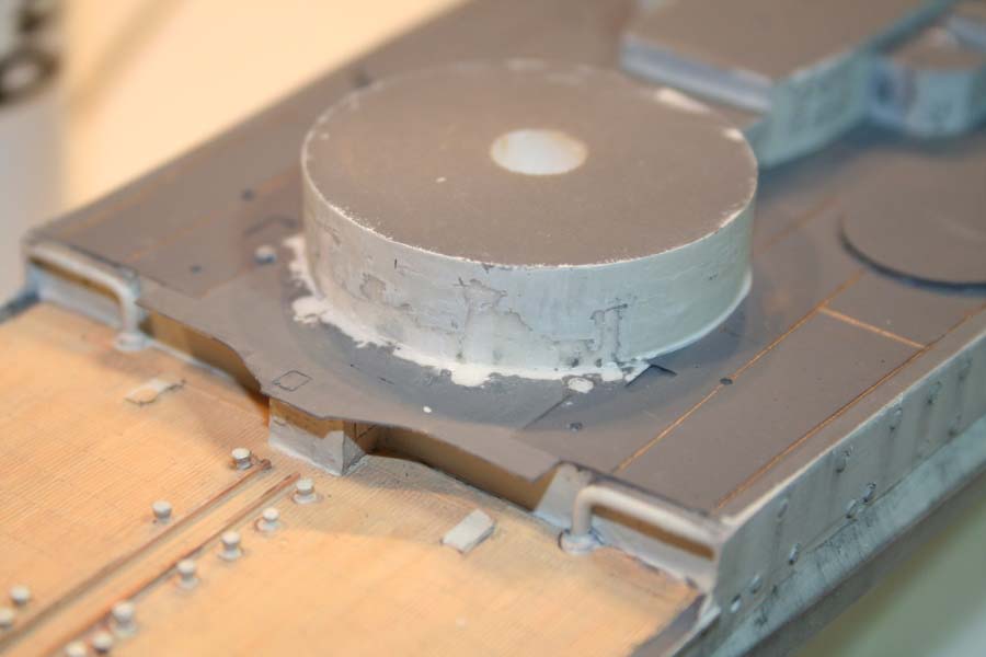
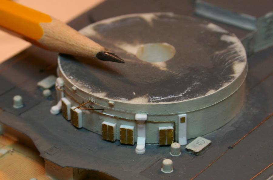
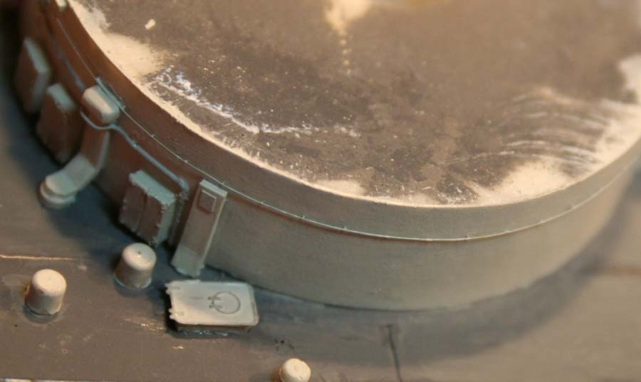
| The aft barbette also had all cast detail removed to facilitate
re-skinning
With new smooth barbettes I set about re-making all the lost detail
comprising of vents and AA platforms. The fore barbette AA platform had
been destroyed by my standing on it accidentally-a fate from which it could
nor recover
|
 |
|||||||||||||||||||||||||||||||||||||||||||||||||||
 |
||||||||||||||||||||||||||||||||||||||||||||||||||||
 |
||||||||||||||||||||||||||||||||||||||||||||||||||||
|
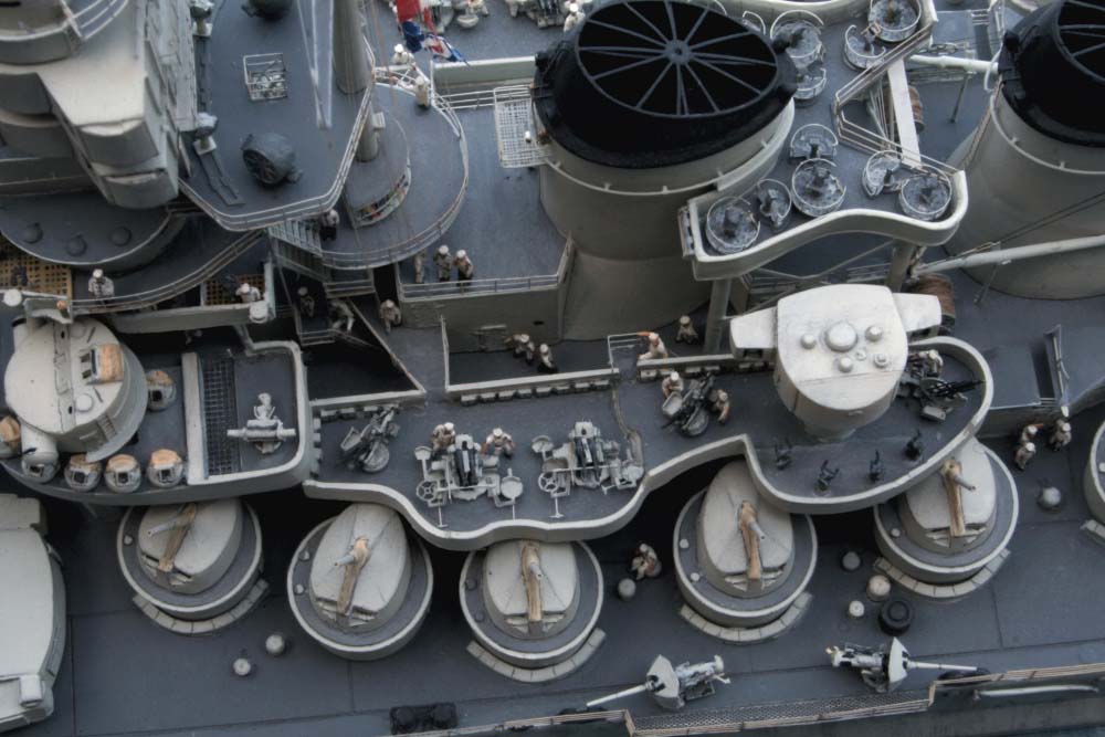
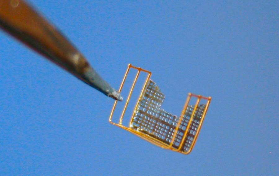
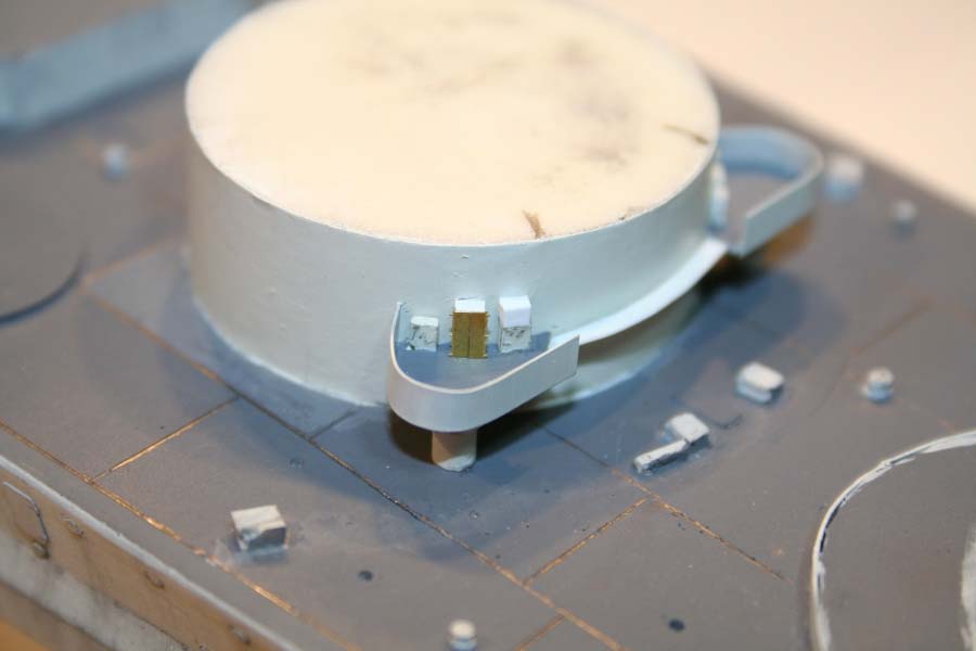
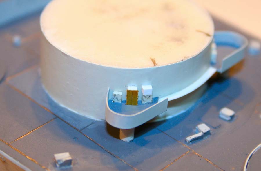
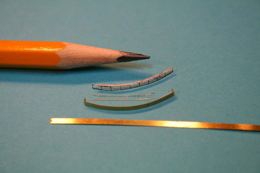
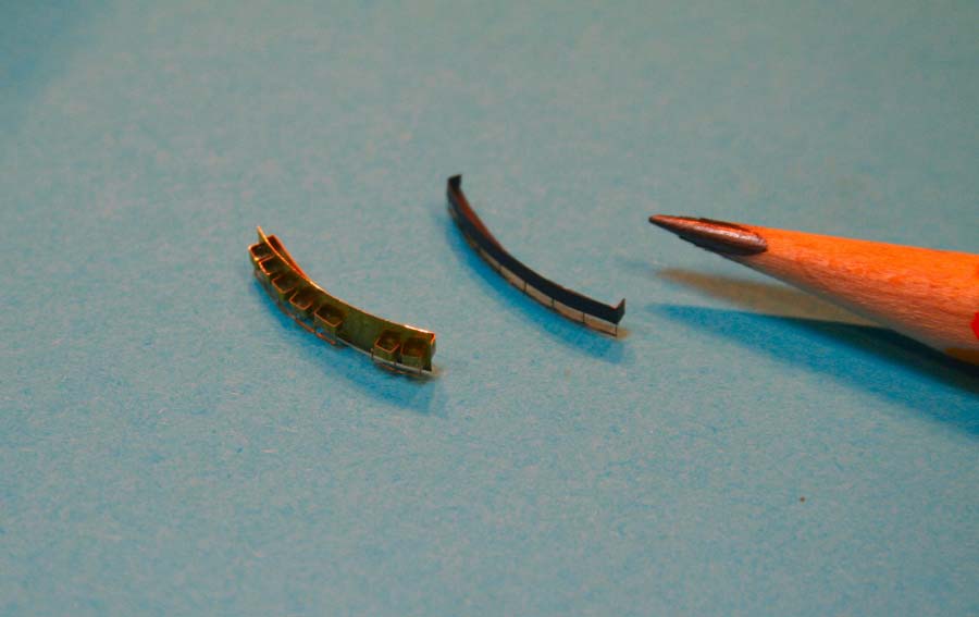
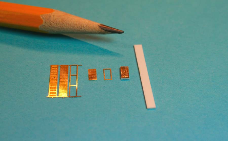
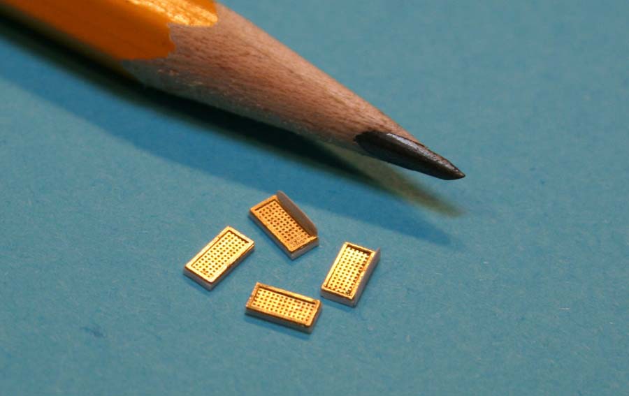
The aforementioned washbasins were a project of their own. After establishing their layout and approximate number from the plans and the Barbiri model photos I made the actual basins of brass strip . For the main basin row around the outer perimeter of the barbette I used 1/700 railing for the supports, brass strip for the outside face and paper for the floor. The sets aft of the turrets had basins both sided of a metal wall. These were made by bending tiny pieces of brass strip and gluing to the curved wall. |
 |
|||||||||||||||||||||||||||||||||||||||||||||||||||
 |
||||||||||||||||||||||||||||||||||||||||||||||||||||
 |
||||||||||||||||||||||||||||||||||||||||||||||||||||
|
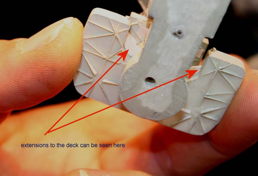
Meanwhile the aft barbette had its missing vents and lockers re-made and the removed handrail added using 1/700 Gold plus GMM railing, the attachment of which owes more to will power than structural integrity! Aft of the barbette the overhanging deck was installed earlier using the neat piece of PE. This was butt glued, faired using heavily applied paint and then pared flat with a blade. The underlying deckhouse however appeared to be too far recessed nowso I skinned the aft edge with styrene strip. |
 |
|||||||||||||||||||||||||||||||||||||||||||||||||||
 |
||||||||||||||||||||||||||||||||||||||||||||||||||||
 |
||||||||||||||||||||||||||||||||||||||||||||||||||||
| Until now I had avoided the over decking of the open underpass in the main superstructure. Although a nice PE infill deck was supplied, I was worried about the possibility of thermal movement of the metal and resin parts-as they were dissimilar materials I feared paint cracking I elected to play safe and made a styrene deck. This was made as a slight force fit and required a little jiggling to sit perfectly flat using a bit of leverage from above and below | 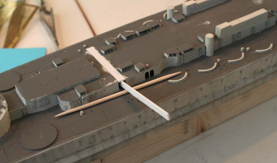 |
|||||||||||||||||||||||||||||||||||||||||||||||||||
 |
||||||||||||||||||||||||||||||||||||||||||||||||||||
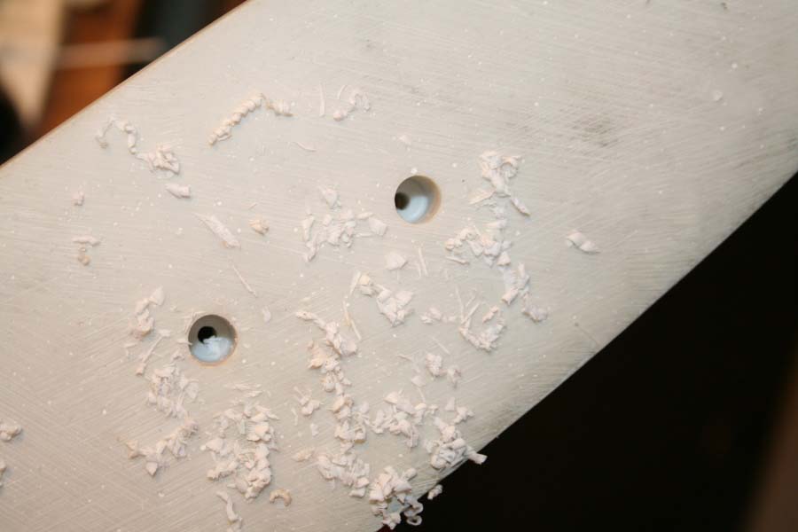
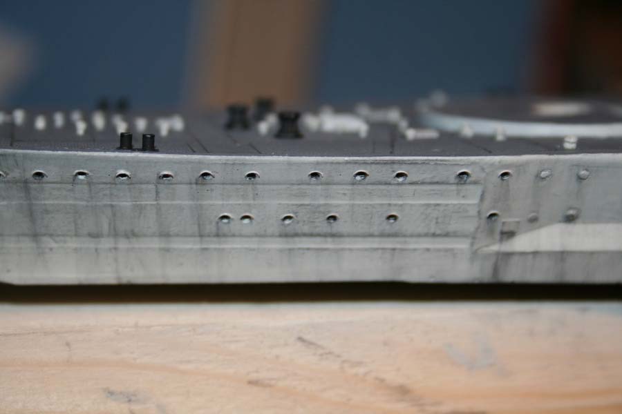
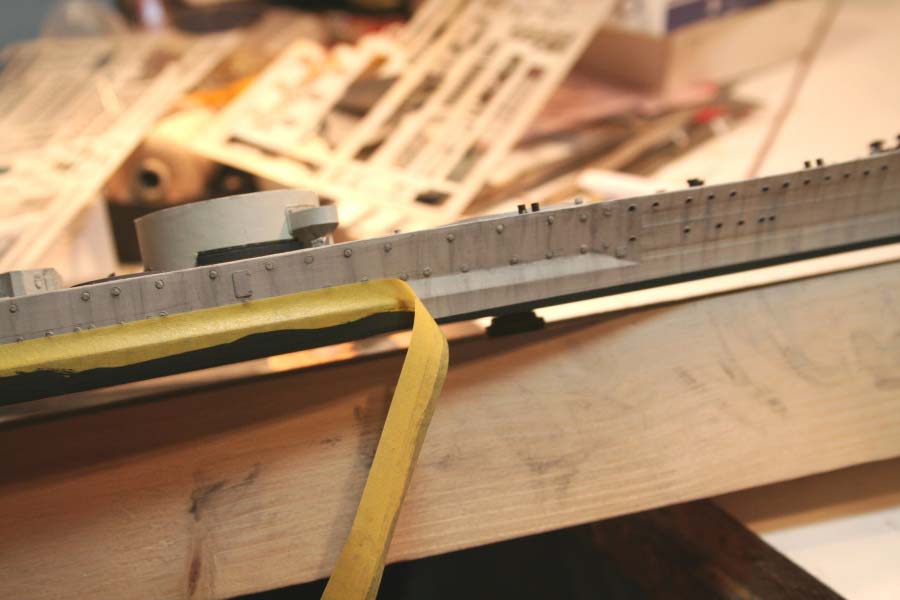
| Because I was depicting the model as during trials, the
photos showed the hull to be heavily streaked. Before applying weathering
I took the opportunity of removing the cast loading doors and replacing
them with some PE items. The hull scuttles that did not have lids were
now furnished with eye-brows. These were created by making a spiral of
copper wire around a drill shank, cutting open and then cutting into semi-circles
The hull had been screwed to a piece of timber using small spacers so that no part of it made contact. This enabled me to paint the boot-topping without handling the hull at all. |
 |
|||||||||||||||||||||||||||||||||||||||||||||||||||
 |
||||||||||||||||||||||||||||||||||||||||||||||||||||
 |
||||||||||||||||||||||||||||||||||||||||||||||||||||
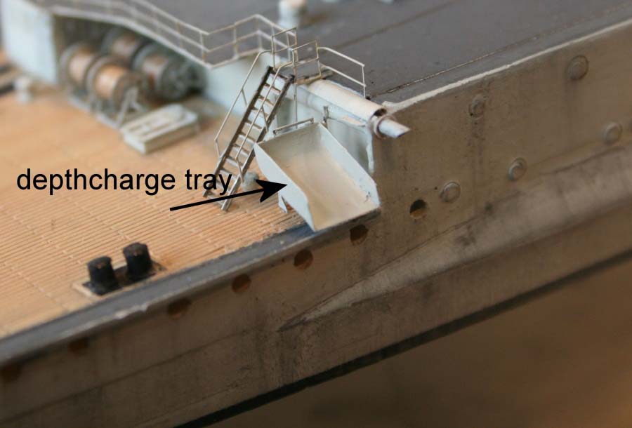
| With the model safely mounted on a building board I concentrated
again o the small details such as the various hatches- some of which were
supplied as PE parts-others which were scratch built from PE scrap and
styrene
Depth charge tray was made of paper base and sides-(now available in PE in latest set...) |
 |
|||||||||||||||||||||||||||||||||||||||||||||||||||
 |
||||||||||||||||||||||||||||||||||||||||||||||||||||
| The Bridge superstructure support columns had ventilator
boxes on two sides.
These were made using a wider variety of PE parts from the scrap box, and installed during a mock-up with guns added. After photos it became apparent that sharpening of edges and paint would be required! |
 |
|||||||||||||||||||||||||||||||||||||||||||||||||||
 |
||||||||||||||||||||||||||||||||||||||||||||||||||||
 |
||||||||||||||||||||||||||||||||||||||||||||||||||||
|
Testfitting the AA platforms also revealed the need to move the walkway apertures that connected the bridge tower to the platform, the piece that was cut out simply being reinserted in the original gap. The AA platforms also needed to have a stairway aperture cut in each side |
 |
|||||||||||||||||||||||||||||||||||||||||||||||||||
 |
||||||||||||||||||||||||||||||||||||||||||||||||||||
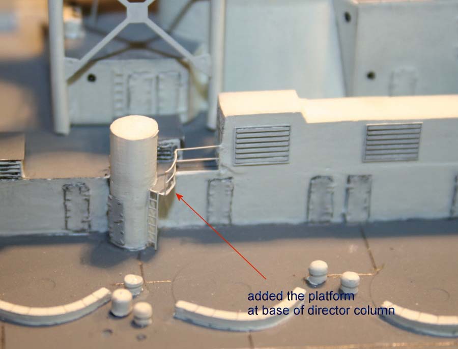
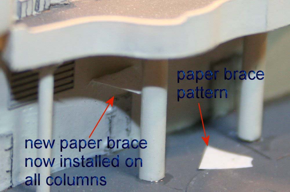
| Before final installation of the AA platforms subtle sanding of the
superstructure, lowering and fine-tuning of the director columns had to
be carried outI took the opportunity to add the ladders and access platforms
made of paper.
Once the AA platforms related satisfactorily to all the other aspects of the superstructure they were glued in place with a flexible epoxyI could not take the risk of a CA joint failing if any movement should occur when the hull was finally screwed to its final water base. The support columns, which are made of styrene rod, have small bracing platforms-these were made of paper, using a paper pattern and adjusted individually for a good fit, tacked in place with thinned white glue and thereafter infused with CA for a permanent bond. |
 |
|||||||||||||||||||||||||||||||||||||||||||||||||||
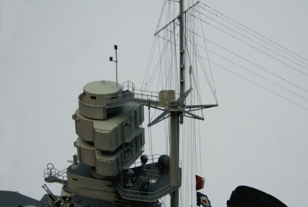
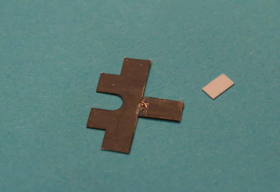
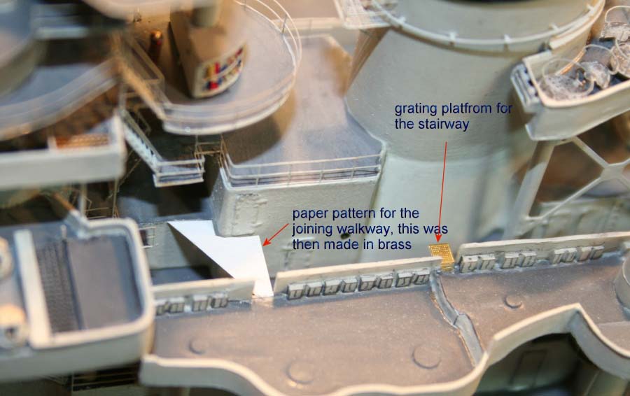
| I could now turn my attention to the making of the walkways,
which although supplied as a nice looking PE part, fell short in length
and angle on my model. Again paper patterns were used to get the perfect
fit-prior to cutting them in paper and installing as before with white
glue and CA
The bottom of the mainmast was in my opinion after examining photos, too thin on its aft face, and the change in angle of the upper structure not sufficiently pronounced. I remedied the former by splitting some appropriate size styrene tubing, and clamping over the resin part. I faced the upper structure in paper and then backfilled with first CA and the white glue. The result, in retrospect is perhaps not as sharp as I would have wished. The upper mast was made of copper tube that was previously cut and shut to give the distinctive taper. The copper rod protruding out of the base was inserted into a deep hole drilled right through the hull to ensure absolute rigidity; important - as that part of the mast was sitting over the undercut passageway that had earlier been infilled with the styrene deck. |
 |
|||||||||||||||||||||||||||||||||||||||||||||||||||
 |
||||||||||||||||||||||||||||||||||||||||||||||||||||
 |
||||||||||||||||||||||||||||||||||||||||||||||||||||
| Once the mast was in place, and I could still access that
area without damaging surround detail I needed to make the cable turning
blocks and wire hawse-openings that operated the boat booms . The hinges
for these were also scratchbuilt.
The 2 x kit supplied large winches were installed however 4 were required; Regia kindly supplied these immediately. At the same time the numerous steam valves and PE handwheels were installed throughout the ship. |
|
|||||||||||||||||||||||||||||||||||||||||||||||||||
 |
||||||||||||||||||||||||||||||||||||||||||||||||||||
| Around the same time I began installing the boat cradles- here as so often the plans misled me somewhat, the aft boat cradles illustrated were never actually fitted, their position being taken by an additional 20 mm AA mount each side. After my error had been pointed out to me I was able to remove them and had to make good the deck. All the well shaped PE cradles supplied looked rather flimsy once installed;, examination of photos showed these to have had triangular bracing gussets; I made mine of paper. | 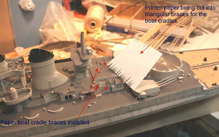 |
|||||||||||||||||||||||||||||||||||||||||||||||||||
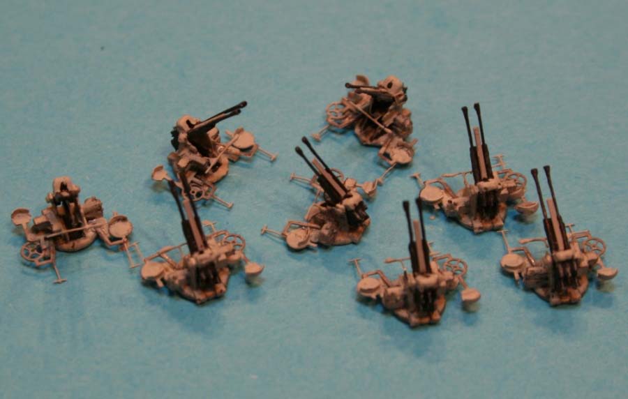
| I knew at some stage I would have to tackle all the AA
mounts a repetitive job, so putting the ship in its glass-case I proceeded
to assemble the kit parts, while adding further detail using scrap brass
PE, paper for seatbacks, copper wire and flattened solder wire .
A pleasurable step towards the final appearance of the ship was adding the main directors to the bridge; these had platforms on their aft edge-supplied as PE with fold up railing, however I prefer the sharpness of using separate railing and platform made of paper. |
 |
|||||||||||||||||||||||||||||||||||||||||||||||||||
 |
||||||||||||||||||||||||||||||||||||||||||||||||||||
 |
||||||||||||||||||||||||||||||||||||||||||||||||||||
| The uppermost level of the bridge had wire beading added to simulate the wind deflector, however when examining photos the kidney shape appeared incorrect- whilst I decided I could live with this minor problem once test fitted it was also too large, overhanging the directors. Resizing and new brass splintershield fixed it easily. | 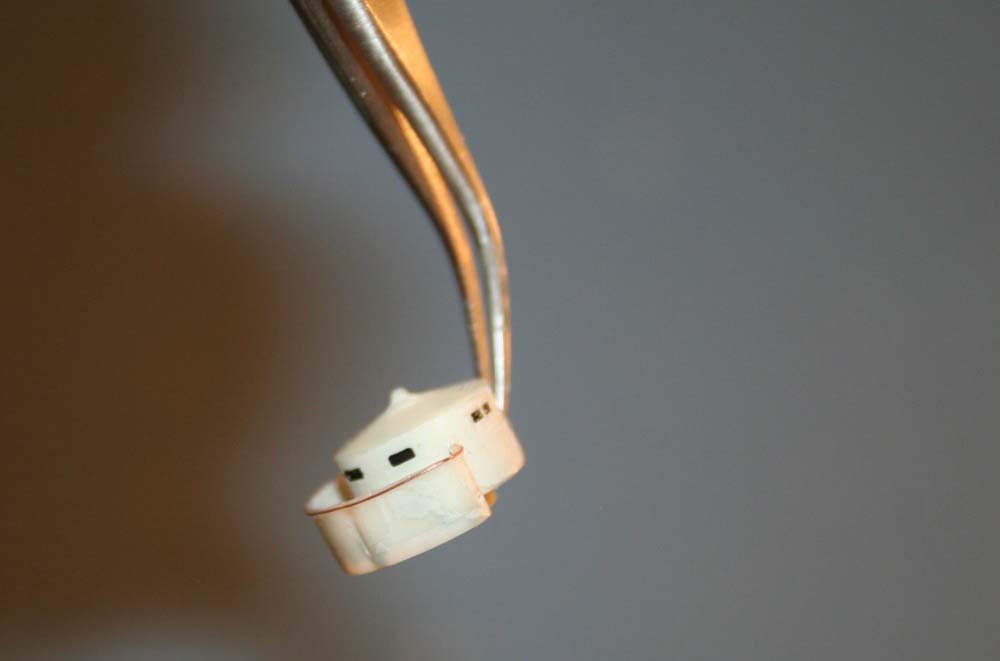 |
|||||||||||||||||||||||||||||||||||||||||||||||||||
 |
||||||||||||||||||||||||||||||||||||||||||||||||||||
 |
||||||||||||||||||||||||||||||||||||||||||||||||||||
| At the same time the superb Photo-etched foremast platform
was installed, with the supplied PE braces-this was an excellent set of
parts that needed only minor fettling to sit correctly. Once furnished
with fine handrails, a wind deflecting bulkhead of paper( a PE item was
suppliedbut I find paper easier to bend!) and ladders where appropriate
the foremast was looking promising. I installed 2 x kit supplied searchlights
along with some scratchbuilt signalling lamps
While in the vicinity of the bridge the large steaming lights and reflector were scratched of brass and paper The Navigation light boxes were made of paper-cut on the double for symmetry. |
 |
|||||||||||||||||||||||||||||||||||||||||||||||||||
 |
||||||||||||||||||||||||||||||||||||||||||||||||||||
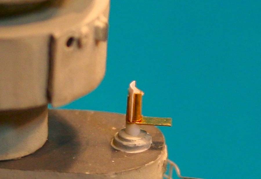
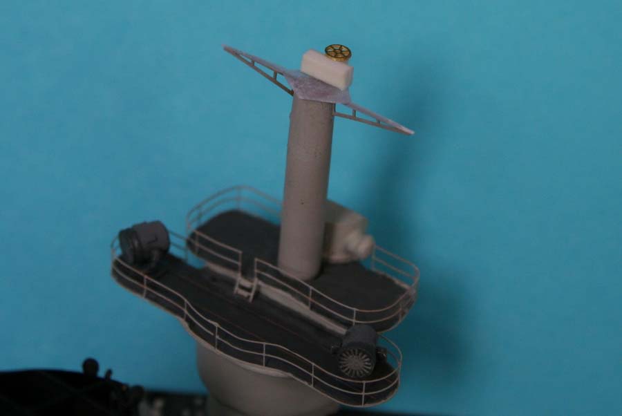
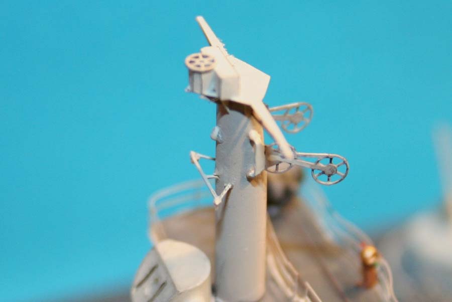
| The mainmast had scratchbuilt platform of paper along with
supplied PE braces added.
Thereafter the supplied PE turning block brackets and pulley sets were assembled and installed along with another scratchbuilt Binnacle-complete with balance weights |
 |
|||||||||||||||||||||||||||||||||||||||||||||||||||
 |
||||||||||||||||||||||||||||||||||||||||||||||||||||
 |
||||||||||||||||||||||||||||||||||||||||||||||||||||
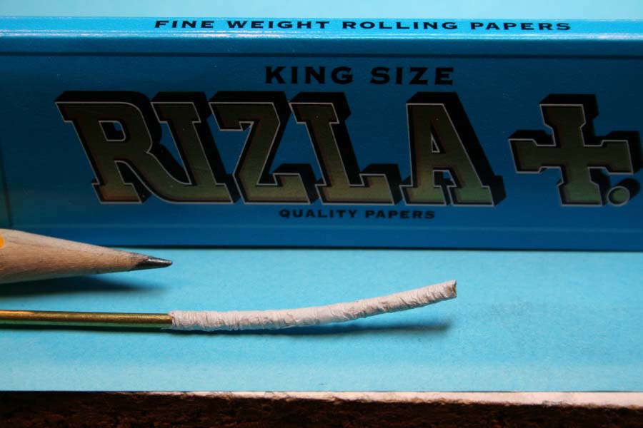
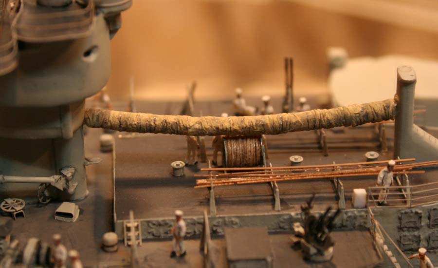
| Descending down the mainmast, the boat booms and boat boom
crutches were scratched.
Roma-at the time of her trials and fitting out carried a large canvas awning that was concertinaed and folded on a line between the mainmast and aft vent structure This was made of a large (handrolling) cigarette paper wrapped and concertinaed around a prevent brass tube former. Once painted the result was very similar to that seen in photographs. |
 |
|||||||||||||||||||||||||||||||||||||||||||||||||||
 |
||||||||||||||||||||||||||||||||||||||||||||||||||||
 |
||||||||||||||||||||||||||||||||||||||||||||||||||||
| The firehose stands ahead of A tuuret were made of a piece of PE handrail, paper gussets and infilled with white glue to give the relief shape, later furnished with GMM Firehose PE parts. | 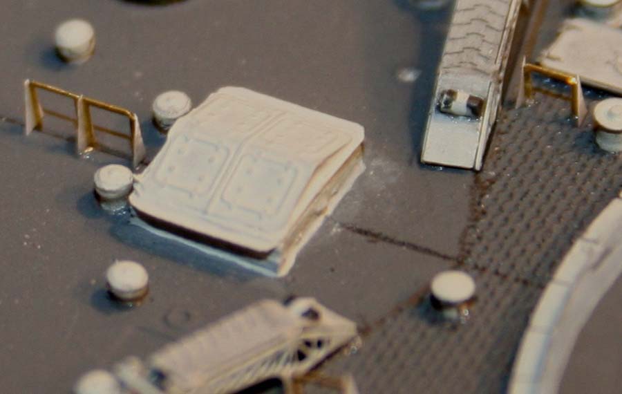 |
|||||||||||||||||||||||||||||||||||||||||||||||||||
 |
||||||||||||||||||||||||||||||||||||||||||||||||||||
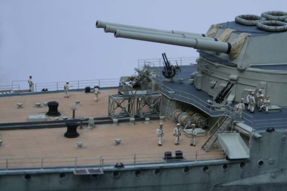
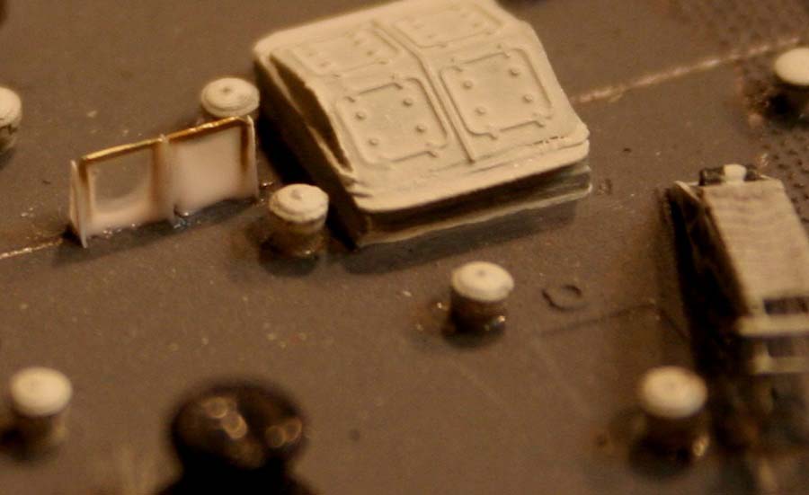
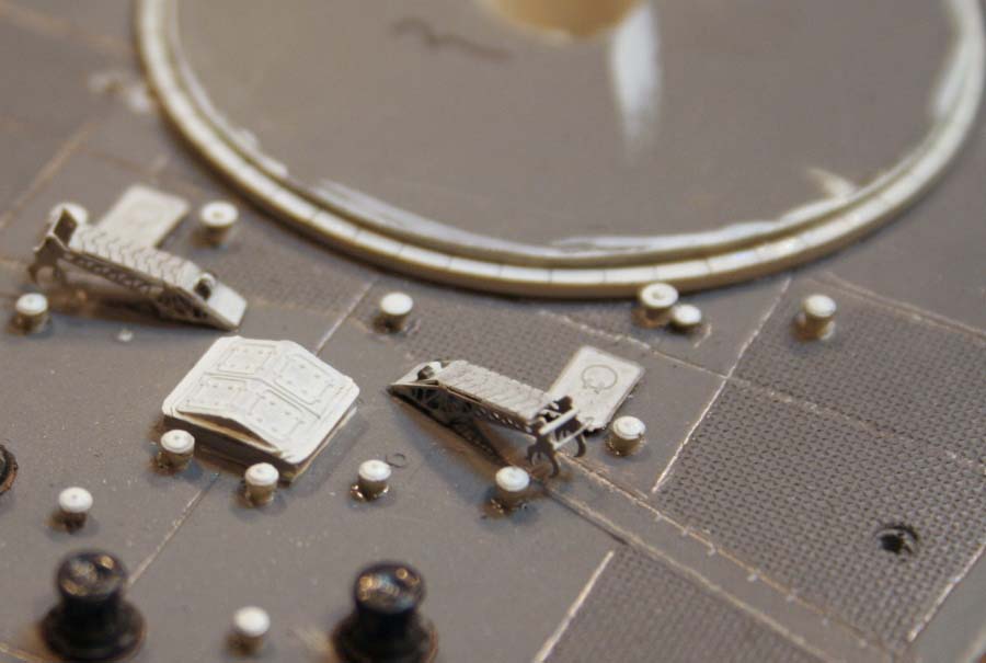
| The ship carried two large Paravanes, stowed aft of B turret.
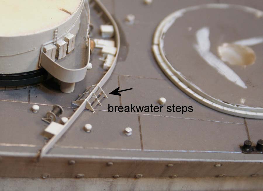
The resin items were enhanced with small brass detail from the scrap box. The fwd main hatch lid was a PE item, as were the beautiful Paravane launching devices which ran on tracks ahead of A turret The forward breakwater had stairs each side to facilitate access to the foredeck, these were fabricated and trimmed to shape later in situ |
 |
|||||||||||||||||||||||||||||||||||||||||||||||||||
 |
||||||||||||||||||||||||||||||||||||||||||||||||||||
 |
||||||||||||||||||||||||||||||||||||||||||||||||||||
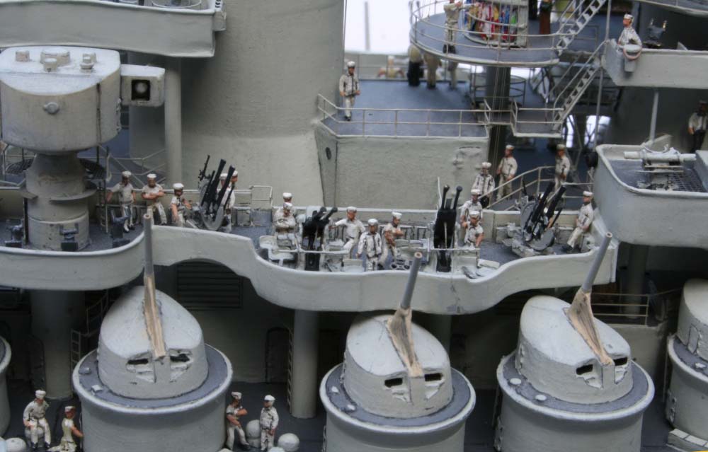
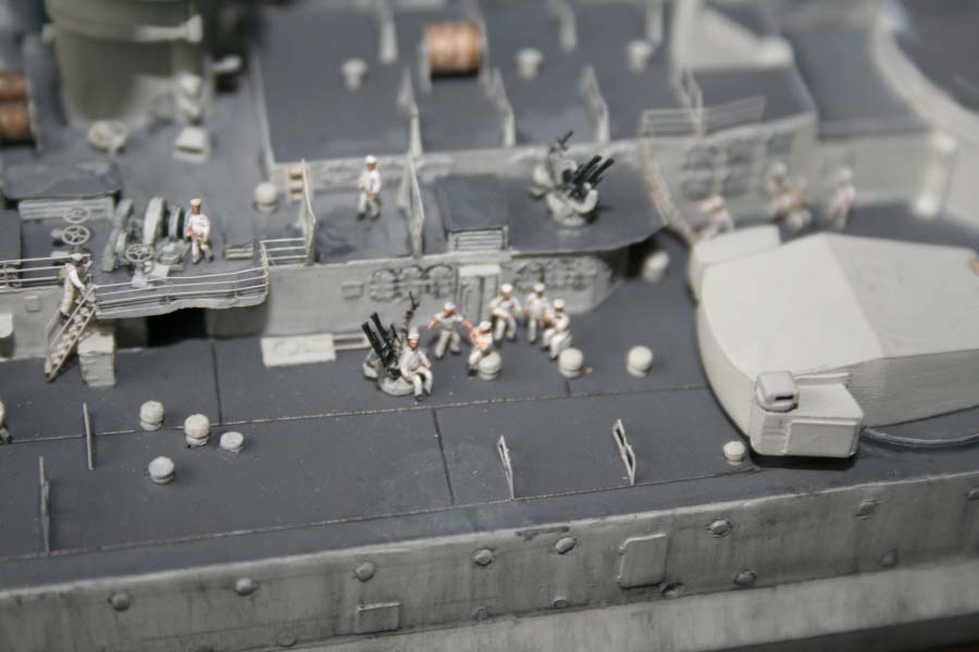
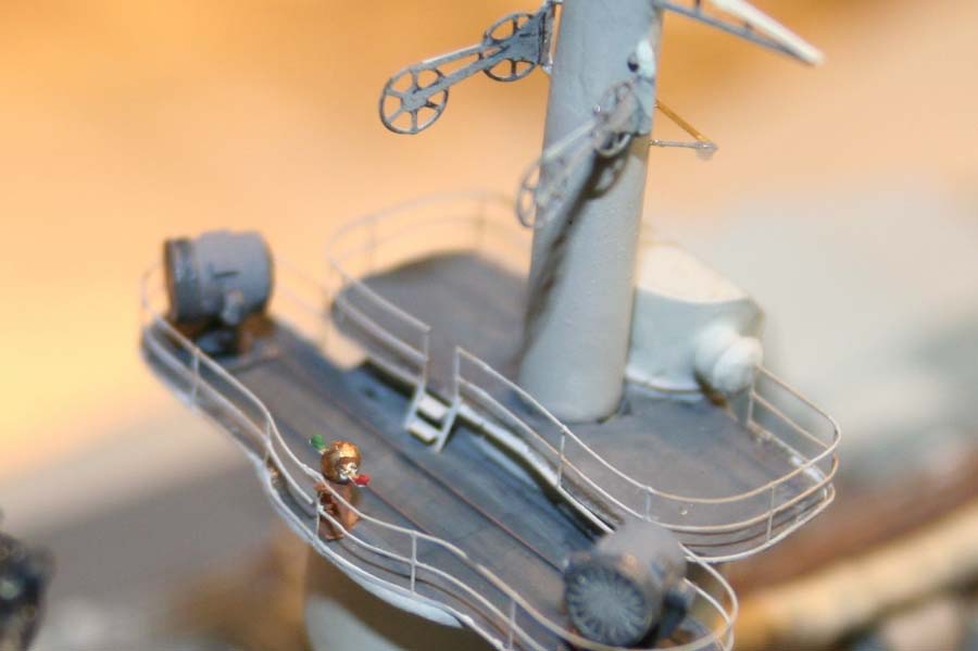
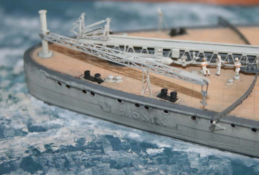
| I wanted to populate the ship in a manner befitting of
the relaxed state of the crew on deck, in animated conversation, returning
to base after another successful set of trials. A miniature production
line was set up, using the excellent lArsenal resin figures.
After a first coat of white -spring/summer uniform- the ratings wore short sleeves- had their flesh parts painted. To simulate the shadows of sunlight, the creases under arms and legs, back of knees, sleeves and collars etc were drawn in using a Hb pencil, sharpened into a fine chisel point in 1000 grade sandpaper continuously, until a to my eyes, a believable result was achieved. These figures were then placed around the vessel in groups, some engaged in avid discussion, some on standby at AA weapons-just in case- others are seeking a moments peace . |
 |
|||||||||||||||||||||||||||||||||||||||||||||||||||
 |
||||||||||||||||||||||||||||||||||||||||||||||||||||
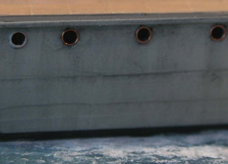
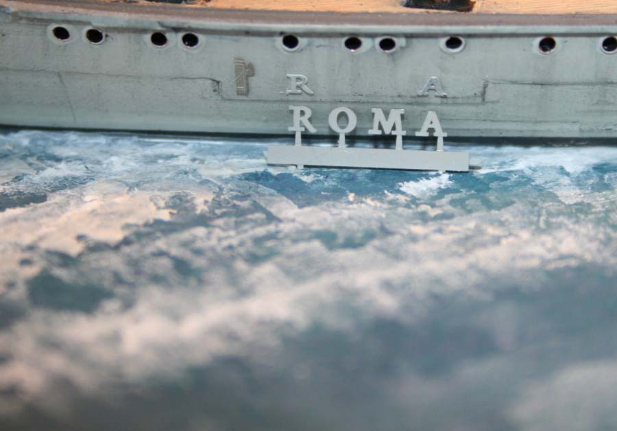
| Thus far the model had taken four months- now the finer
detailing started to bring the ship alive. The previously drilled portholes
around the quarterdeck now had copper surrounds made and installed-this
sharpened up the appearance considerably.
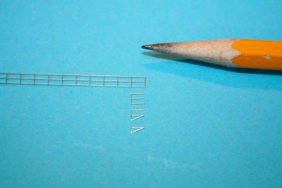
The name lettering, beautifully create in PE was a pleasure to install; along with bow and stern crests- even the shields on the aft Sampson posts were included! |
 |
|||||||||||||||||||||||||||||||||||||||||||||||||||
 |
||||||||||||||||||||||||||||||||||||||||||||||||||||
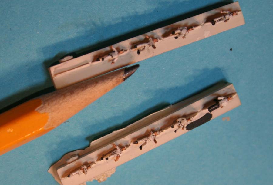
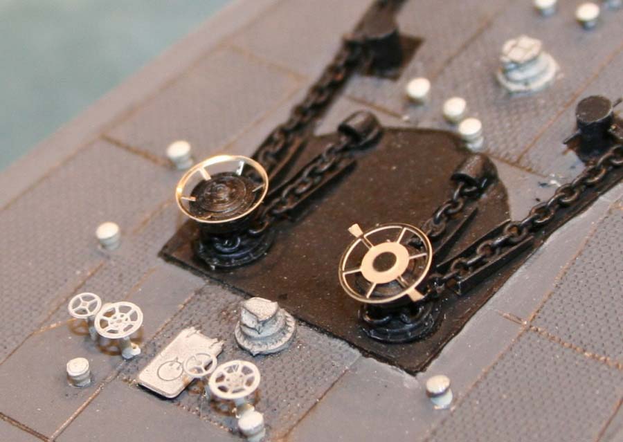
| The anchor windlasses had large hand wheels, these were supplied as flat PE parts, however on the real thing these would have been dished . Out came my trusty doming punch set; the photographs illustrate well the before and after effect. | 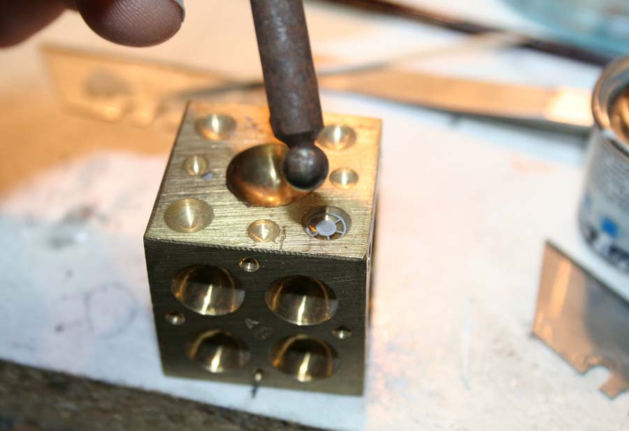 |
|||||||||||||||||||||||||||||||||||||||||||||||||||
 |
||||||||||||||||||||||||||||||||||||||||||||||||||||
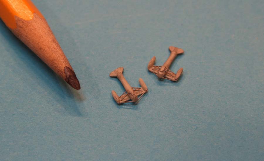
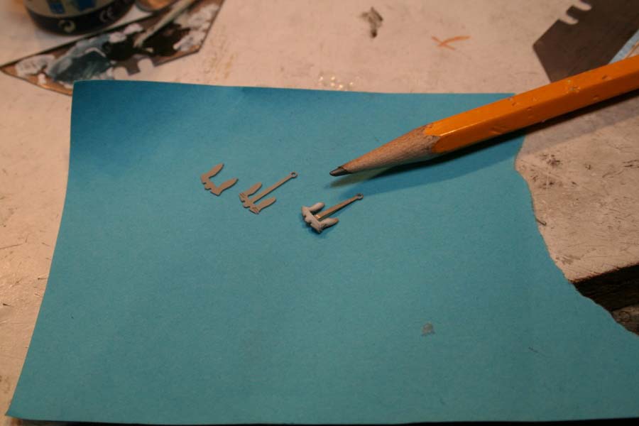
| The anchors were supplied as PE items-and due to the limitations
of the medium were far too flat for my liking. I doubled up the fluke parts
to give them some substance. I then added white glue to give the anchors
the appearance of being a casting rather than a pressing.
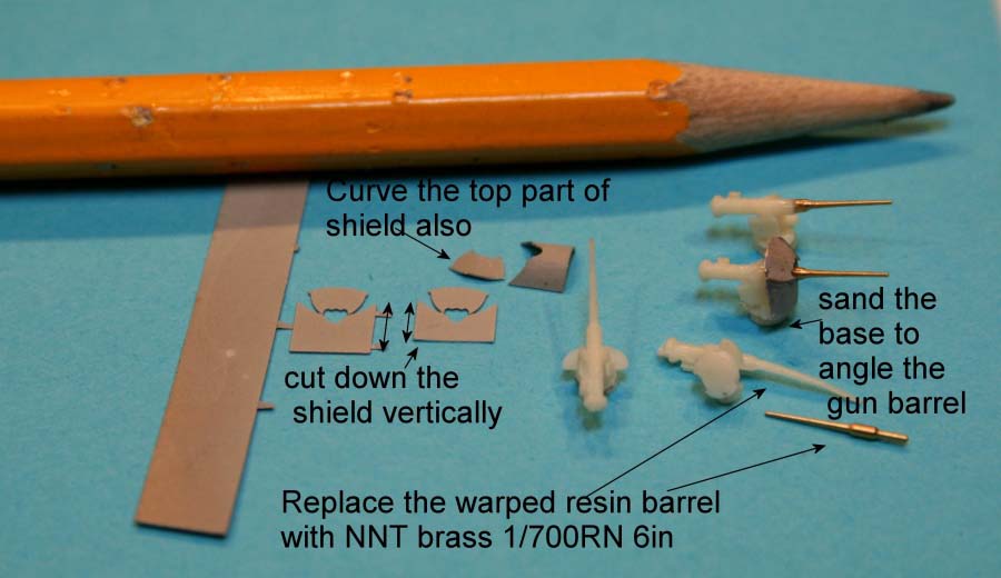
The starshell firing guns were modified and detailed using the kit casting as a basis. The guns were given some elevation at rest by lightly sanding the base |
 |
|||||||||||||||||||||||||||||||||||||||||||||||||||
 |
||||||||||||||||||||||||||||||||||||||||||||||||||||
 |
||||||||||||||||||||||||||||||||||||||||||||||||||||
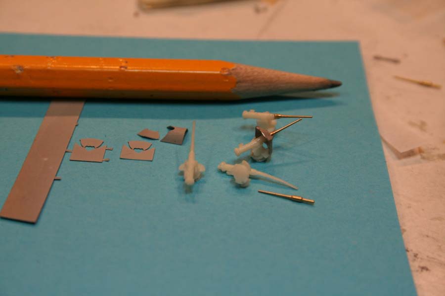
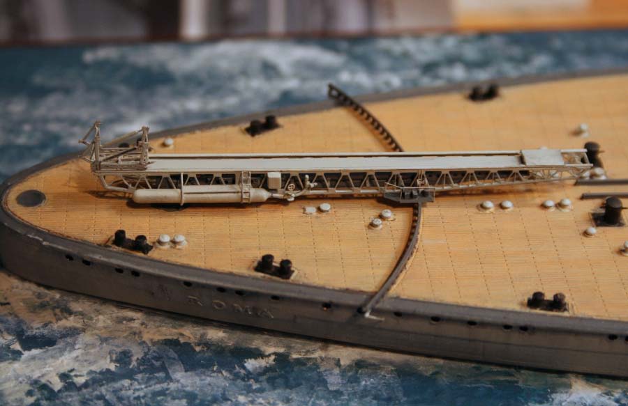
| The aircraft catapult was assembled using the supplied
PE sides, however I cut away the deck and made a new narrower item that
was lowered. The sides were then made of styrene microstrip along with
the airtanks of styrene rod. The PE aircraft trolley had additional bracing
added to the legs and base. Pipework of solderwire and PE hand wheels completed
the job.
The traversing operators platform was made of paper floor, control boxes and tracking gear of brass PE scrap. |
 |
|||||||||||||||||||||||||||||||||||||||||||||||||||
 |
||||||||||||||||||||||||||||||||||||||||||||||||||||
 |
||||||||||||||||||||||||||||||||||||||||||||||||||||
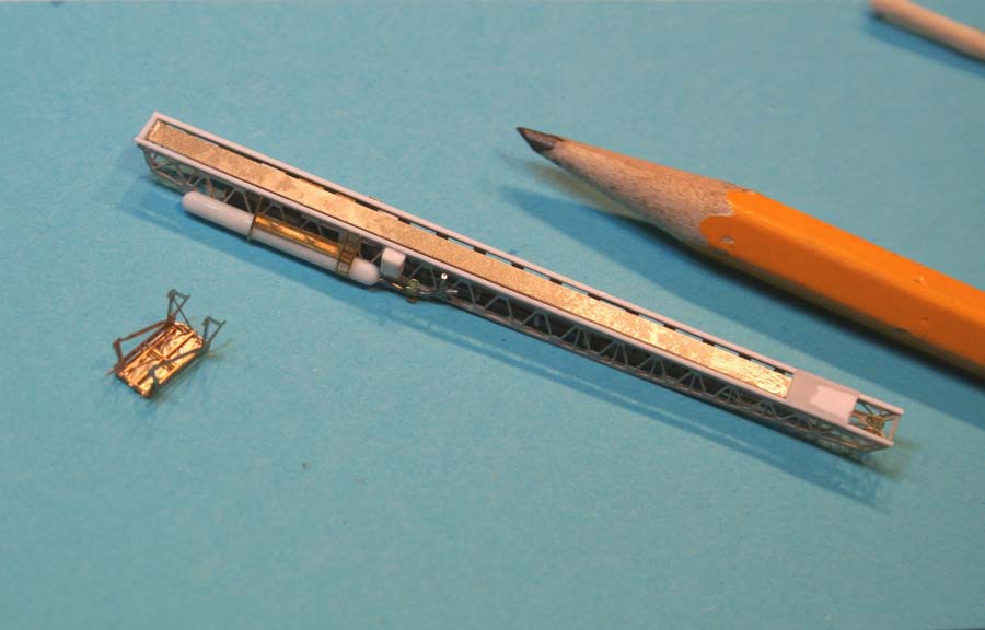
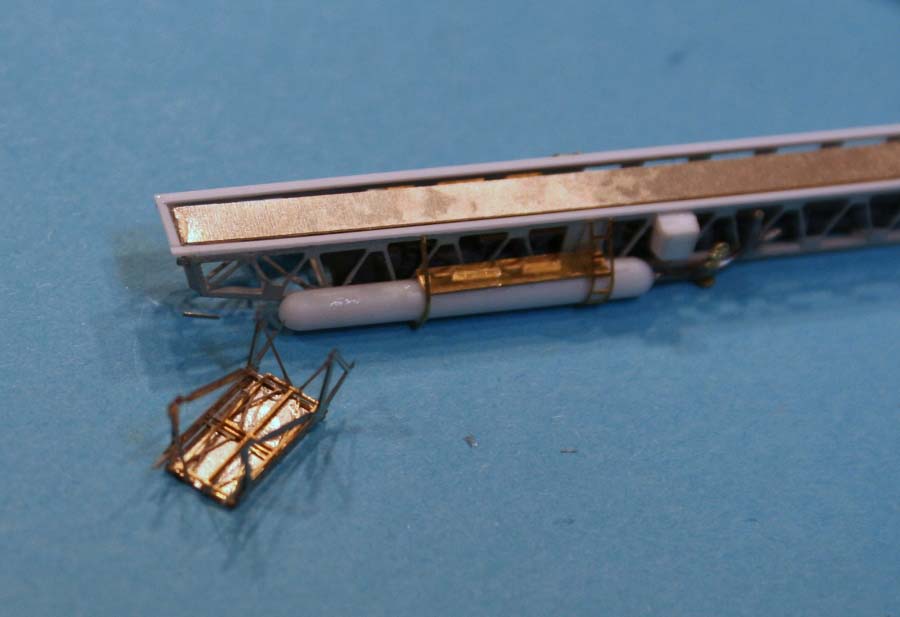
| The catapult-traversing rail was supplied as a PE itemin
retrospect perhaps it should have been made a bit lower
However from overhead
it looked to flimsy to my eyes and I reckoned to be able to bear half the
weight it would need a greater cross-section-more akin to railway track.
I lined the inboard face with styrene micro-strip, added the platform ends
and bracing.
The storage aircraft dollies had top, bottom and vertical bracing added and interconnected with a paper platform. |
 |
|||||||||||||||||||||||||||||||||||||||||||||||||||
 |
||||||||||||||||||||||||||||||||||||||||||||||||||||
 |
||||||||||||||||||||||||||||||||||||||||||||||||||||
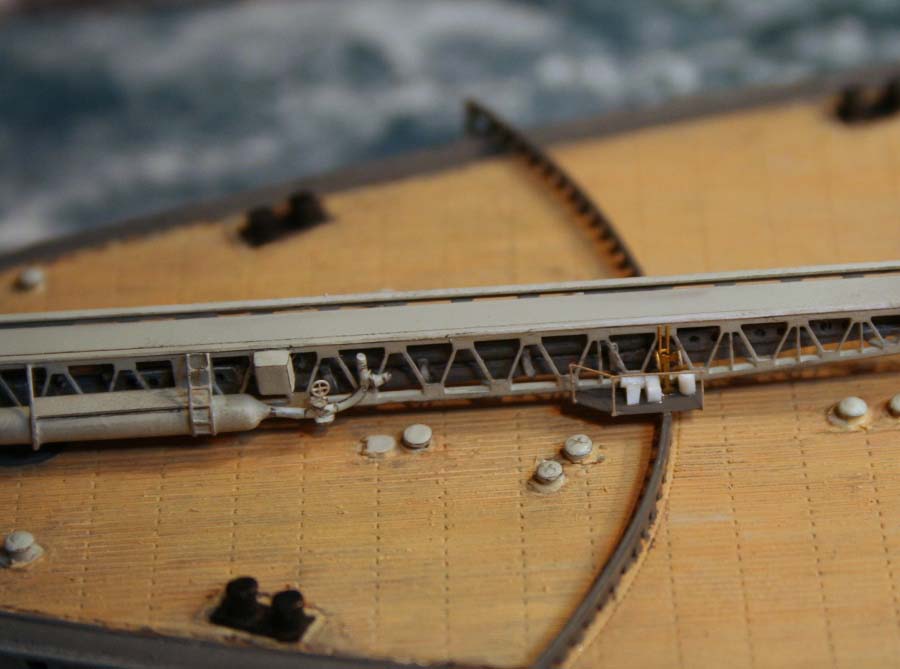
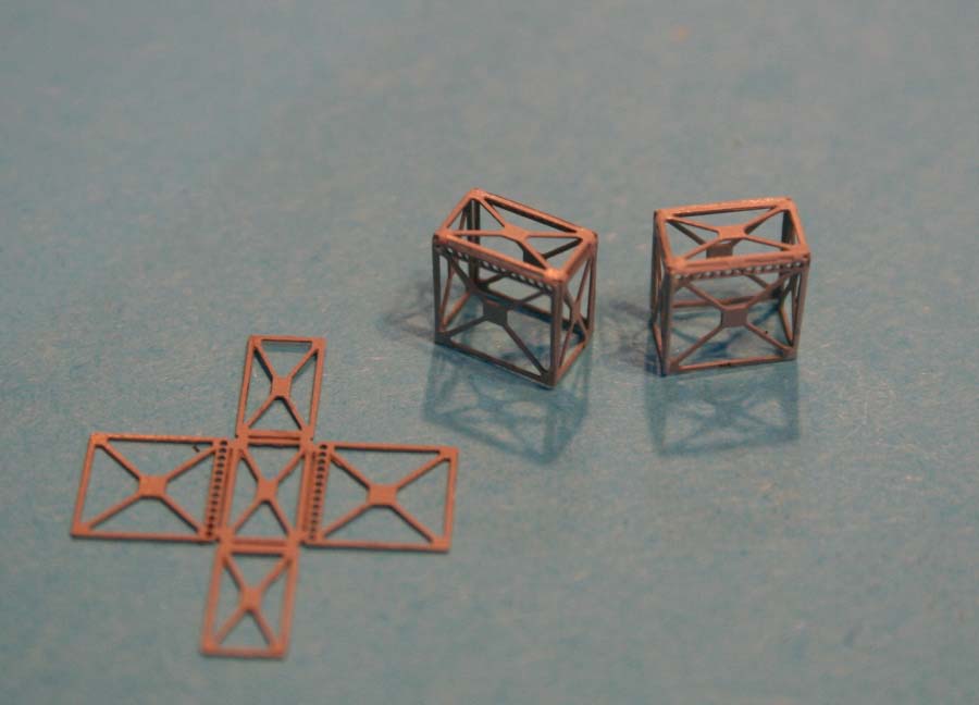
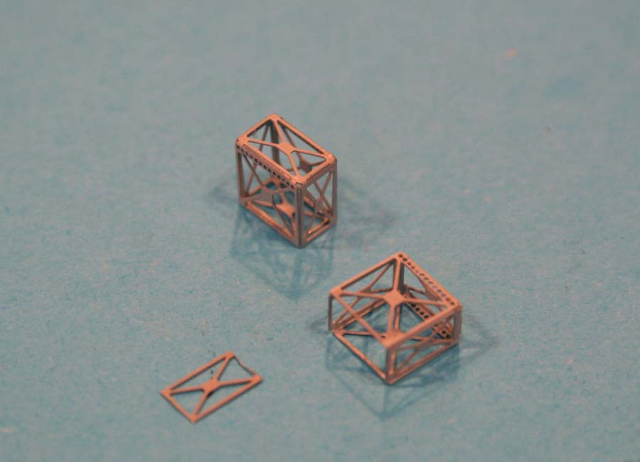
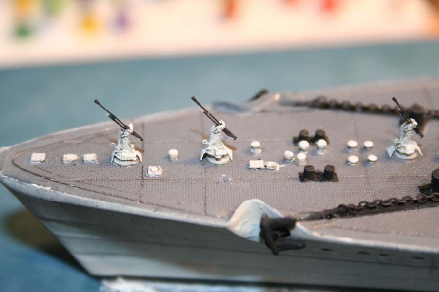
| The disappearing AA mounts on the bow had supplied as
PE parts the neat half door flaps that made the lid when the mounts were
lowered, along with the mount frames in resin. I made the flared muzzles
using white glue on brass wire and a host of small PE parts from the scrap
box.
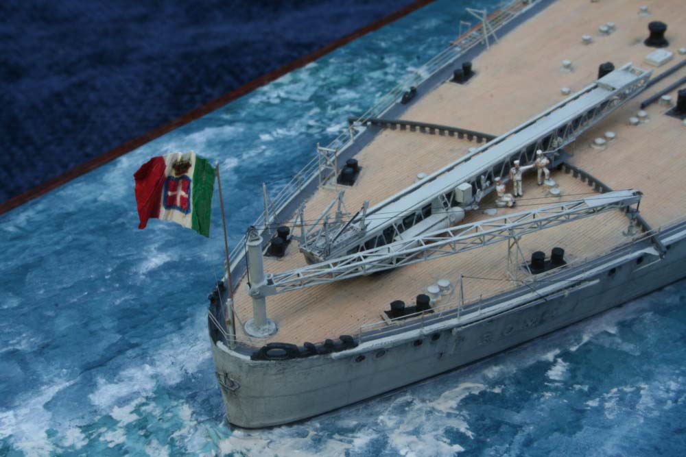
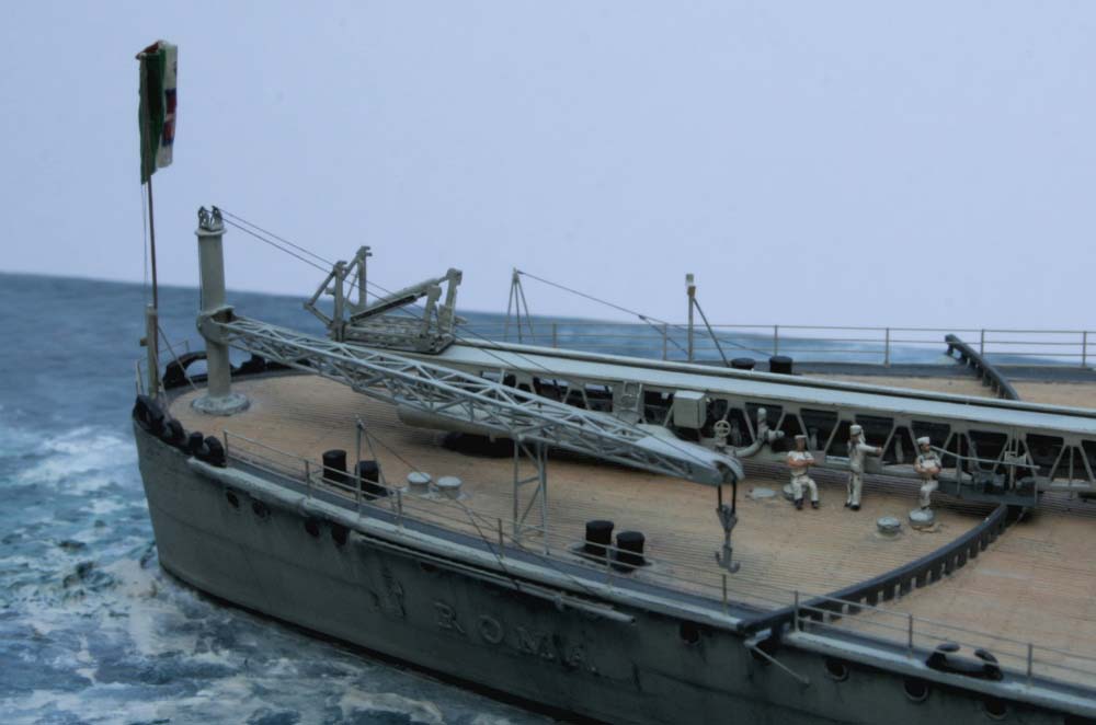
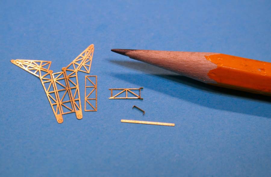
The seaplane crane jib was supplied as a PE fold up itemI chose to cut it into four pieces and reassemble with glue-this reduced its overall circumference by eliminating the fold tabs and as the same time obviated the gaps thereby formed. The crane boom had rests on both sides of the ship, these were scratch-built from a perfectly suited 1/700 WEM crane boomand given a cradle made of brass strip. |
 |
|||||||||||||||||||||||||||||||||||||||||||||||||||
 |
||||||||||||||||||||||||||||||||||||||||||||||||||||
 |
||||||||||||||||||||||||||||||||||||||||||||||||||||
|
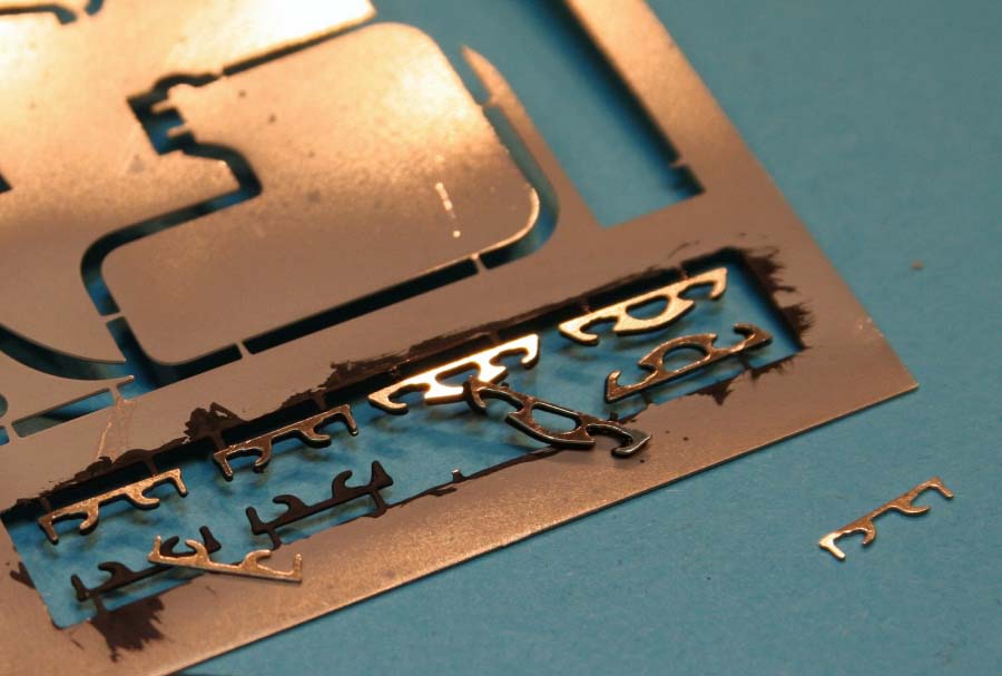
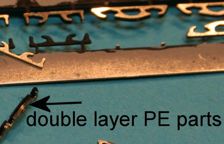
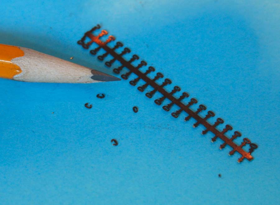
The ship was extensively fitted with rope handling fittings, having large and small fairleads, rope rollers fore and aft. Although these were supplied on a sheet of thick PE, they still however looked too thin to my eyes and I ordered an additional identical PE fret from Regia Marina, glued them back to back and infilling with white glue. The smaller fairleads were cut from Model Railway etched carriage door handles(!) And backfilled with white glue once installed to give the appearance of a casting. |
 |
|||||||||||||||||||||||||||||||||||||||||||||||||||
 |
||||||||||||||||||||||||||||||||||||||||||||||||||||
 |
||||||||||||||||||||||||||||||||||||||||||||||||||||
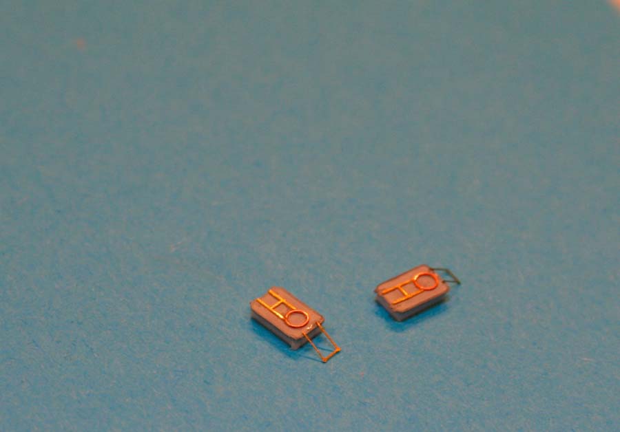
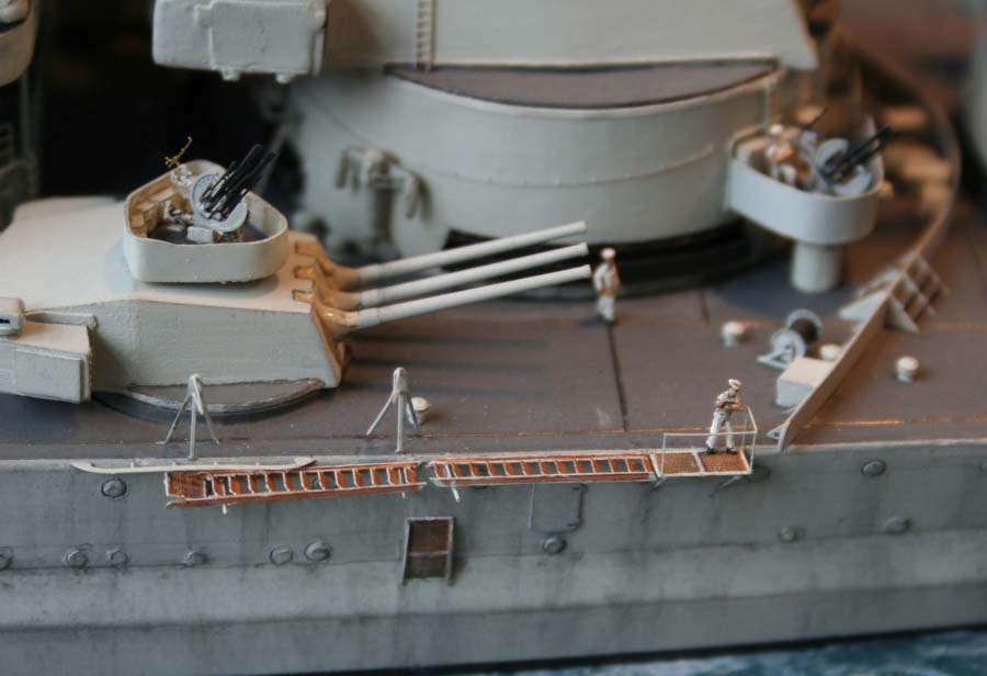
| The accommodation ladders-which were merely swung up when
on short trial sorties and the stowed hinged platforms on the hull sides
were made using mainly WEM items. The hinged brackets that supported the
raised accommodation stairways, both stowed and deployed, were made of
handrail sections.
The boat booms were made of stepped tubing and furnished with PE ladder stock to simulate the foot boards running along the top of them |
 |
|||||||||||||||||||||||||||||||||||||||||||||||||||
 |
||||||||||||||||||||||||||||||||||||||||||||||||||||
 |
||||||||||||||||||||||||||||||||||||||||||||||||||||
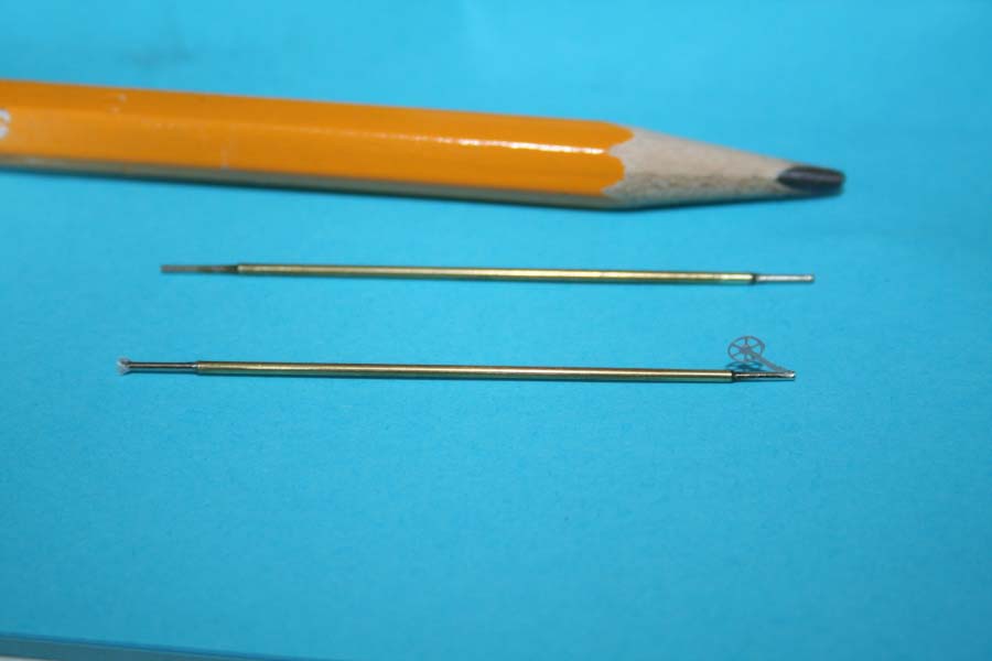
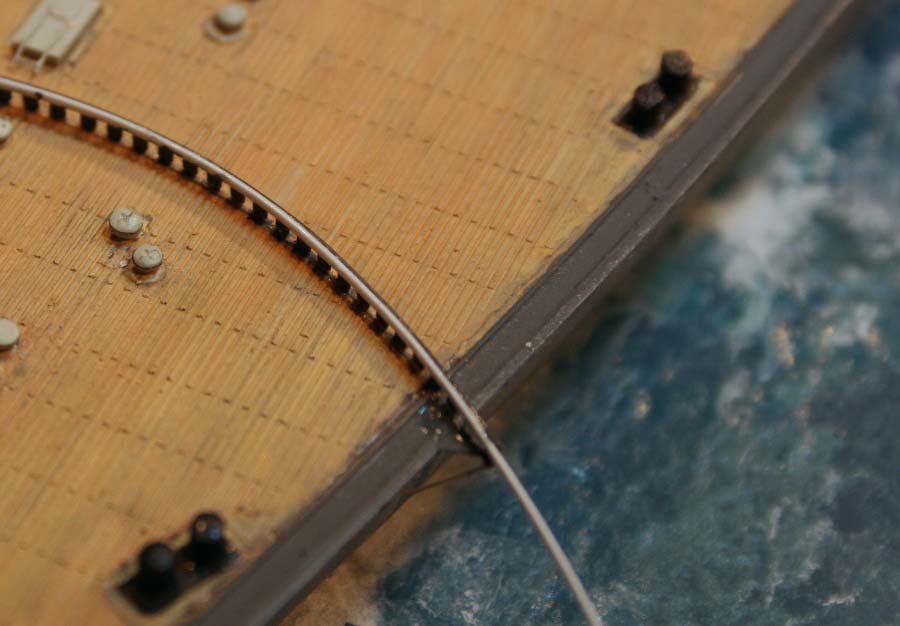
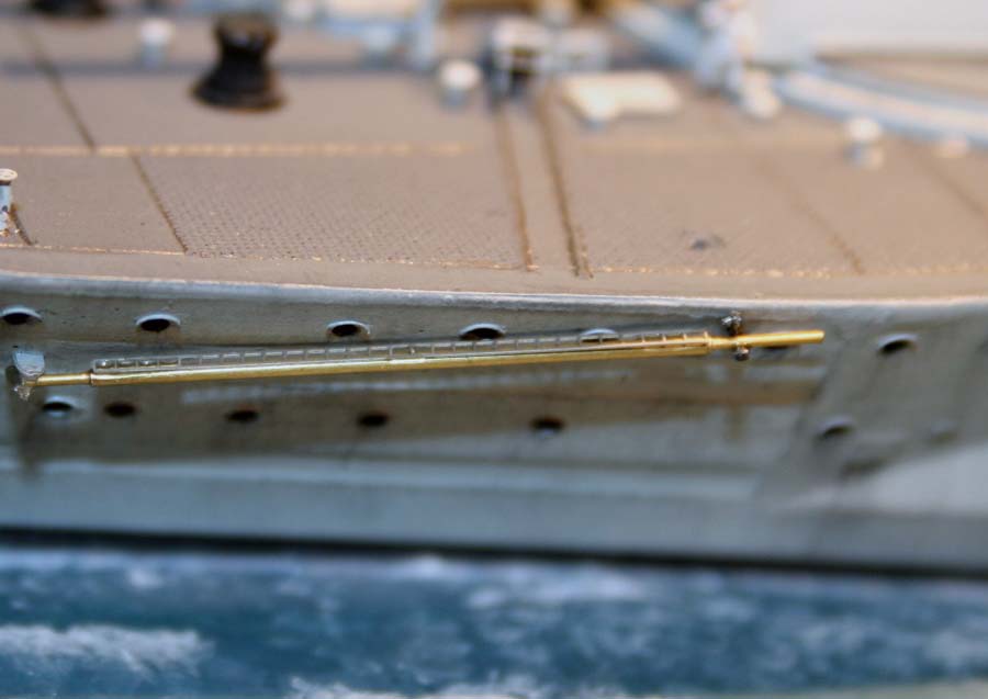
| Tapered stainless steel topmasts and tapered nickel -silver yards were
fitted to the masts, along with signal lights and other small protrusions,
prior to fitting the weather deck handrails. These I had specifically made
by Peter Hall, as the kit-supplied items were without a spurn-water bottom
rail. Whilst more accurate, I had already cut away the cast resin waterway,
so had little choice. Careful examination of photos of the real ship and
the Barbieri model showed differing stanchion spacing throughout the ship.
These custom rails feature the square base, along with the stanchions protruding just above the wire cable. Once the rails had been applied a small bead of thinned white glue concealed any small gaps and acted as a structural fillet. The rails were applied in very short lengths only to counter any differential material expansion and contraction as well as allowing fine-tuning of stanchion spacing to allow for fairleads etc. |
 |
|||||||||||||||||||||||||||||||||||||||||||||||||||
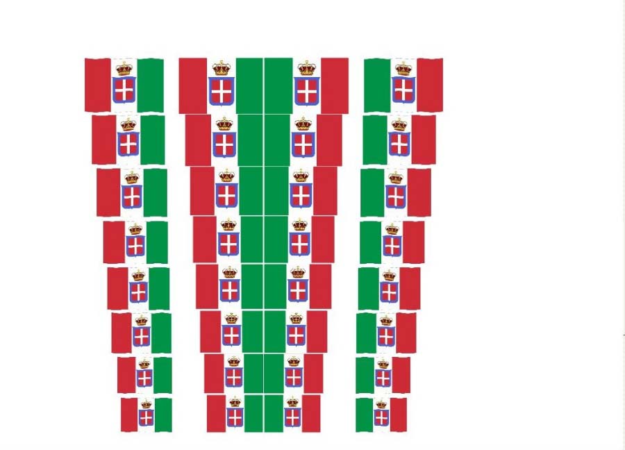
| The ship was mounted on its glass case base on a calm sea of embossed
artists watercolour paper, coloured in a Mediterranean hue on a sunny day!
I painted the model using Humbrol No 147and no 27, having first colour matched to my tinlets of WEM colourcoats. I rigged the model in my usual manner using stretched sprue in black and grey for standing rigging, tan sprue was used for signal halyards. The Flags were made on the PC using a large image redrawn in serif 5.0, in various sizes to allow choosing the most appropriate size and printed on white decal paper. |
 |
|||||||||||||||||||||||||||||||||||||||||||||||||||
|
||||||||||||||||||||||||||||||||||||||||||||||||||||
| Conclusion | ||||||||||||||||||||||||||||||||||||||||||||||||||||
|
Roma was a beautiful but ill-fated ship. The Axis kit captures the essential shapes of the ship very well, but is let down somewhat by not being fully and finally developed. Many of the failings found with this kit however can be found with other manufacturers in some form or another. A great contribution to the buildability of this kit are the extensive
photoetch frets developed by Regia Marine along with the detailed instructions.
Any modelship of this complexity will be an extensive project, but with perseverance and patience a fine rendition of this magnificent vessel can be built from the Axis models starting point. My thanks go to: Robin Bursell for discussion and mentorship
But an especial thank you must go to Giampiero Galeotti of Regia Marina, who tirelessly answered my questions, supplied insight and know-how as well as photographic evidence to guide me. Jim Baumann June 2008 Main references used: Erminio |Bagnasco/Auguto de Toro Littorio class battleships (Italian text) Orrizonte Mare booklets 3 ½ Imagini booklet A2 1:100 plans from the Associazione Navimodellisti Bolognese Giancarlo Barbieri 1:100 model Various on-line resources and books |
||||||||||||||||||||||||||||||||||||||||||||||||||||
| More of Jim Baumann's work. | ||||||||||||||||||||||||||||||||||||||||||||||||||||

© ModelWarships.com