IJN Soryu
in 1/144 Scale
By Bill Waldorf
| Hello again fellow modelers! Well I am back with another update on the construction of the IJN Soryu scratchbuilt in 1/144 scale. Things are moving along well and in this article I will show the construction of the flightdeck. As some of you may or may not know, this model is going to permanent display at The Patriot Points Museum in Mt. Pleasant, South Carolina, home of the USS Yorktown. The museum is inside the real Yorktown, so as a result I am rather excited about things. My wife and I are going to personally deliver the model the first week of Sept. As a result of this time frame, I am unable to give a detailed description of the build of the flightdeck. I have 30 days to complete the project so I am sure you will all bear with me. I will touch on a few things so you can all get a good idea of the progress so far. I apologize for the lack of detailed step-by-step procedures. Let's go to the photo's. | |||||
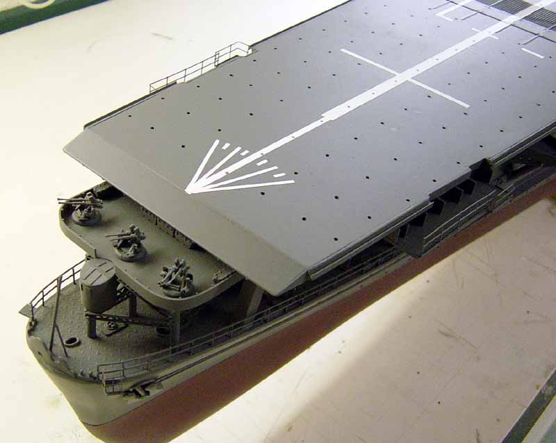
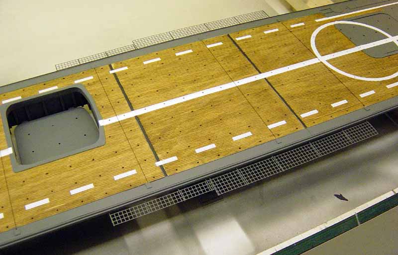
| Here is the fwd. half of the flightdeck looking from pt.
side. Anything you see grey is sheet styrene plastic. Note a/c tie down
locations. White lines are taped off and airbrushed.
Amidships area of the flightdeck again from the port side. Wooden deck area is scribed basswood. Note expansion joints which are real, not painted on. I used strip styrene, . 030" back to back then laid the wooden flightdeck sections in between the joints. Note the 4 arrestor wires, made from rigging thread. Safety netting is brass p/e mesh supported by pieces of strip styrene. Also visible is the center elevator in the lowered position, about halfway to the hanger deck. Tie down locations are just a 1/16" hole drilled in the deck. I made a grid pattern from the plans and then center punched all the tie down locations, then drilled them out. |
to enlarge 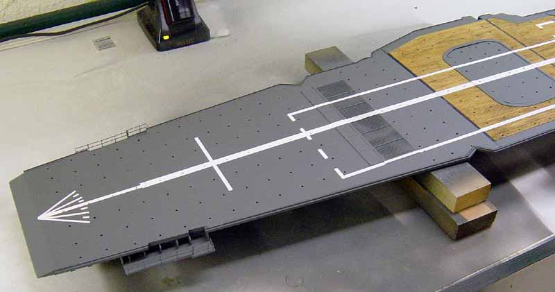 |
||||
 |
|||||
| Aft end of the flightdeck, looking from portside again. Note the framework for the safety netting has been installed on the very aft end of the deck. I'll use fine fabric netting here, painted a tan color, which I will install soon. All lines were airbrushed, very time consuming but worth the effort. | 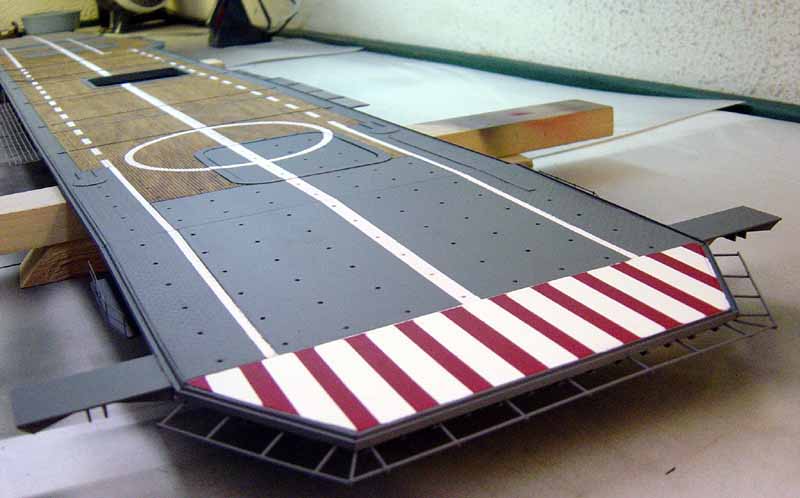 |
||||
| Here's a good shot of the aft elevator location. All the elevators were cut out, trimmed then reinstalled to the deck rather than just painted on. Also note the searchlight and a/c handling crane in the lowered and closed position. The circle you see was tricky to mask off and airbrush!! Narrow steel areas along the edge of the wooden flightdeck are diamond plate. If you look closely you can see the pattern. | 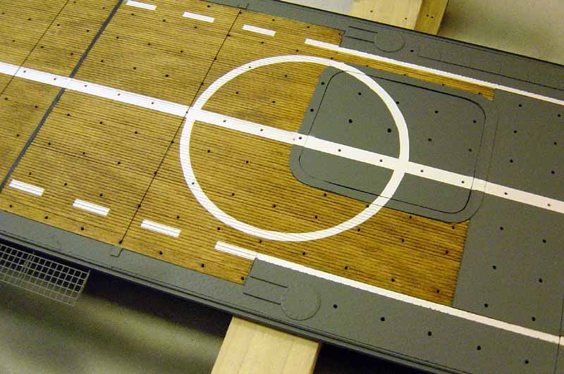 |
||||
| Amidships elevator area again. Note the barrier arm to the left of the photo. Made from p/e brass and strip styrene. Look closely and you will see the eaves trough along the edges of the flightdeck, made from styrene H-Column. | 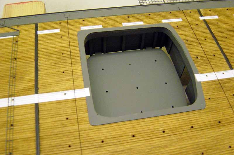 |
||||
| Fwd. end of the flightdeck showing the windscreen in the lowered position. Made from brass p/e mesh and strip styrene. | 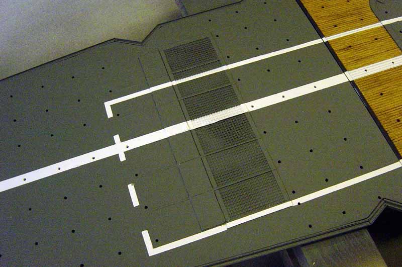 |
||||
| Here is a shot of the center elevator looking from underneath the deck. Basically a box with h-columns added for detail bracing. Note the sliding hanger deck doors fore and aft. I added a couple of cross braces and the attached the elevator platform to them. | 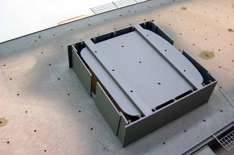 |
||||
| A shot of the aft elevator in up position. Again note the elevator platforms were cut out then re-installed to make things more realistic. Larger hole in the right of the photo is for a locator pin, made from wood dowel to aid in final setting of the flightdeck to the rest of the ship. | 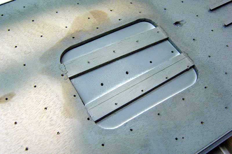 |
||||
| Here's a view of the aft end of the flightdeck looking from underneath. Note the bracing I have added. I could have done more but I decided to call it good at this point because you really can't see this part when the ship is displayed. Unless you crawl beneath the display base that is!! The lesson is, don't detail some part of the model that will not be seen a whole lot, if at all. I concentrated efforts on other areas of the ship that are more visible. All parts here are styrene plastic. | 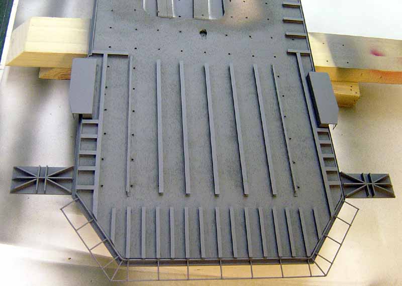 |
||||
| Here's the bracing on the fwd. end of the flightdeck. | 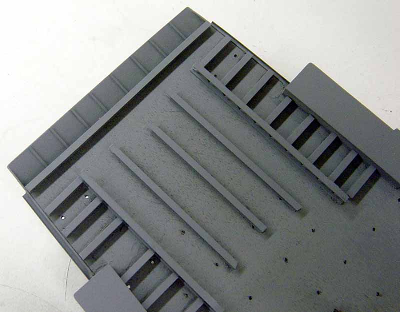 |
||||
| The fwd. elevator looking from underneath. | 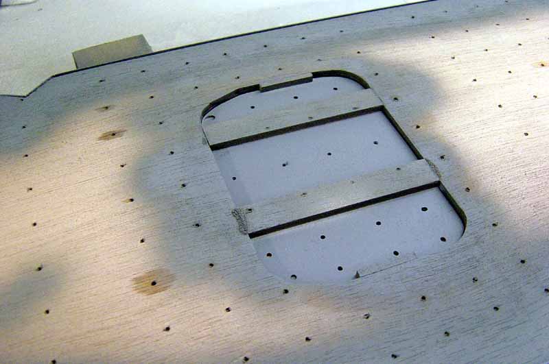 |
||||
| Hole cut into gun deck to accommodate the center elevator in lowered position. Photo # 19 shows how all this fits together | 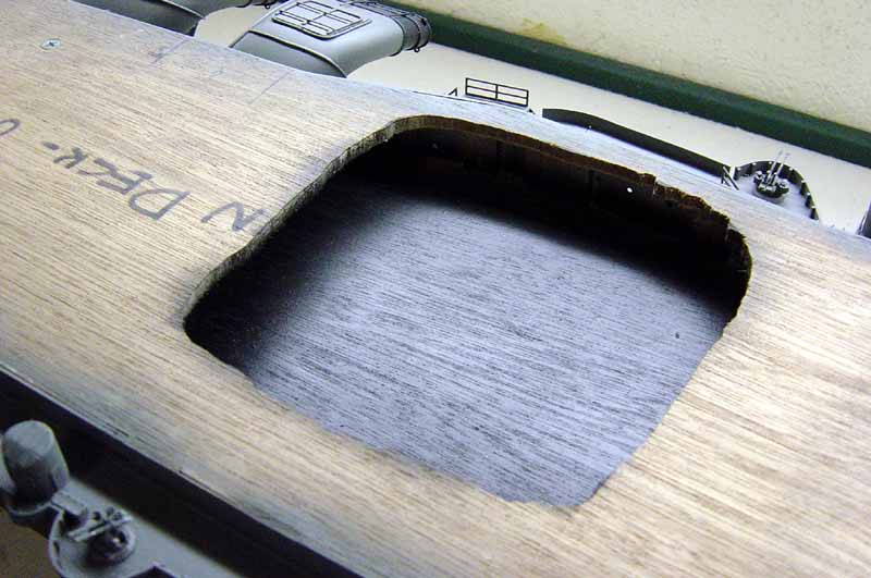 |
||||
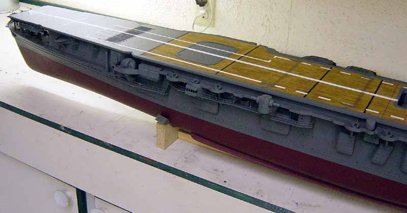
In these photos you can see the flight deck placed
on the hull but not yet permanently installed. I will make final adjustments
here before permanent placement.
|
|||||
| Here we have the aft end of the ship looking from port side. As you can see, the limited bracing I have done under the deck adds more detail to the overall picture. Again, limited but effective. | 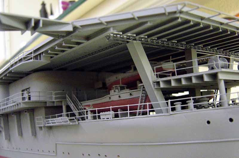 |
||||
| Aft end of the flightdeck again. Note framework for safety netting. | 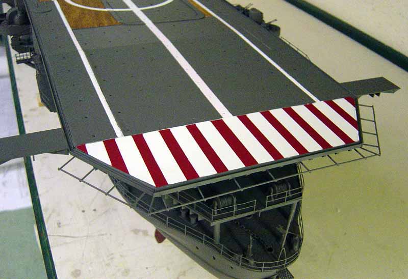 |
||||
| Center elevator position. Compare this with photo# 12. Note how all things come together sooner or later!!!. | 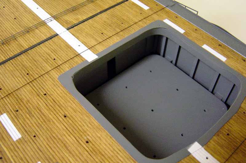 |
||||
| In this shot is the aft port side 12. 7 cm gun position. Note a/c safety netting made from p/e mesh. Just to the left of the gun you can see the comm. antenna motorized mount. Antennas not yet mounted. | 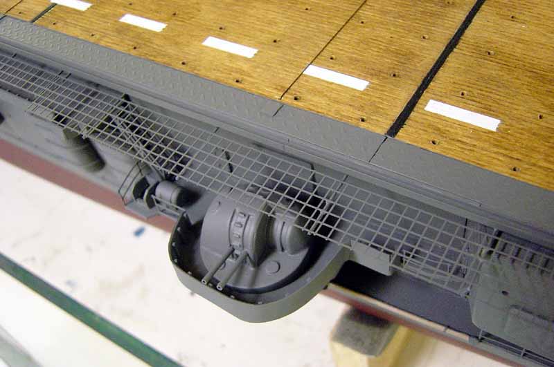 |
||||
| Port side view of the fwd. end of the ship. Again notice how the limited use of bracing adds to the overall appeal of the model. Anchors were stolen from a Revell Corvette kit. I went through 5 anchors in various scales before I stole these as they seemed to work out the best. | 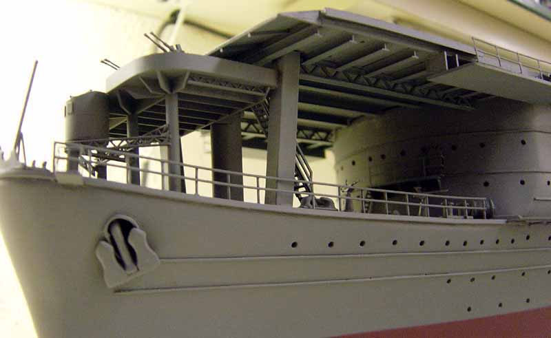 |
||||
| Nice view of the flightdeck. | 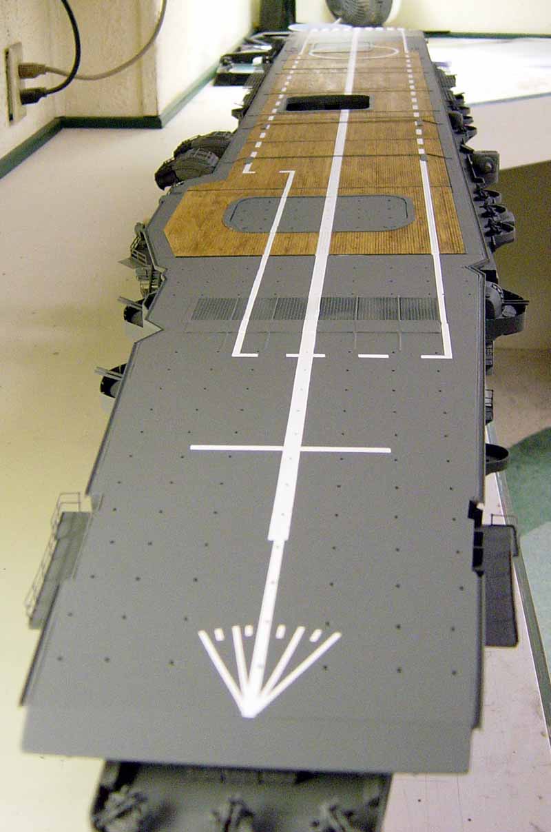 |
||||
| Bow area looking from stb. side. | 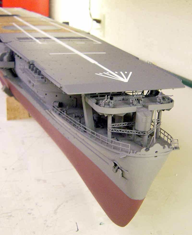 |
||||
| Starboard side view of the fwd. 12. 7 cm gun mounts. Note the windscreen and fwd. elevator. | 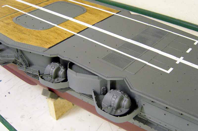 |
||||
| Another good shot of stb. side amidships area. Note the funnel assemblys. These were a real challenge to build!! Also a good study of the barrier arm assembly. and the center elevator. | 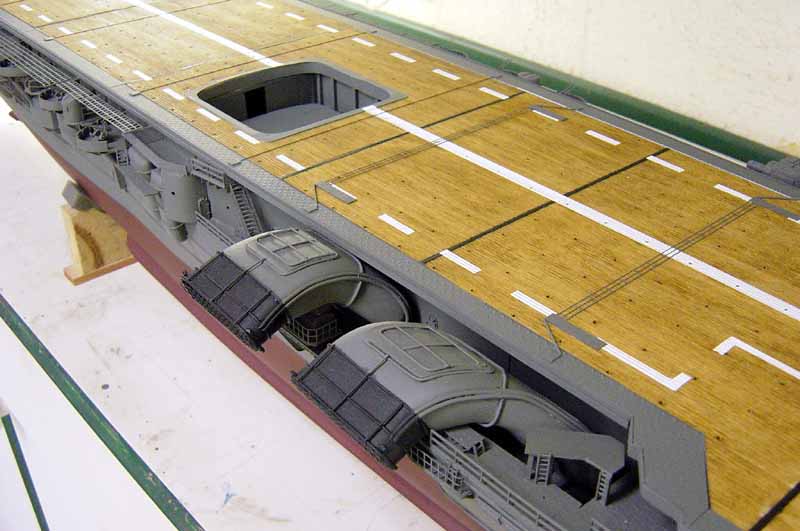 |
||||
| Center elevator again looking from stb. side. | 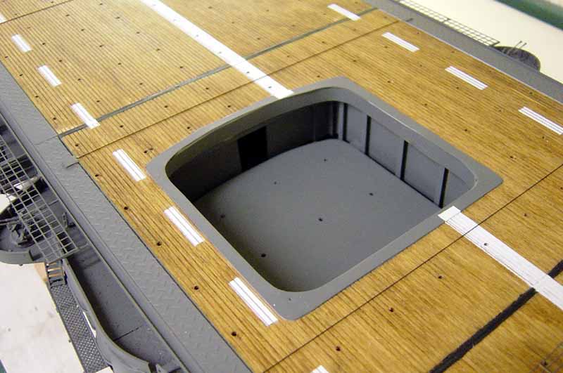 |
||||
| Aft view of the flightdeck from stb. side looking slightly underneath. Again note all the added details which adds interest to the model, IMHO!! | 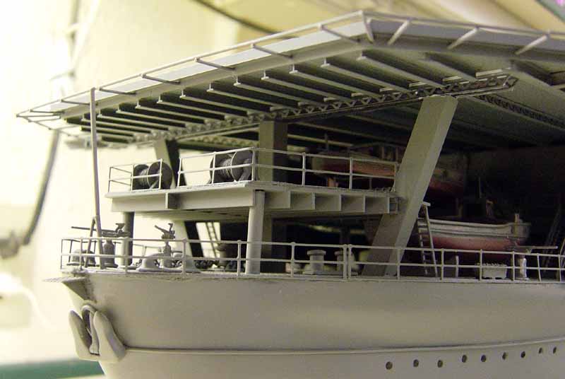 |
||||
| Long view of the flightdeck looking aft to fwd. Again note airbrushed lines. | 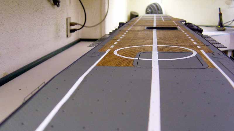 |
||||
| Here is a prototype of one of the Val type 99 dive bombers which were carried by Soryu and most other Japanese Carriers. I hope to have 10 of these on deck along with A6M2 Zeros and Kate Torpedo Bombers. A total of 20 to 30 aircraft on deck if I can build them all in time! | 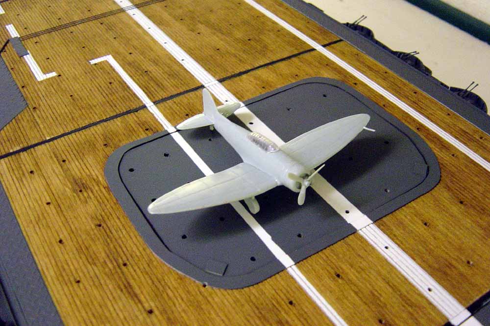 |
||||
| Aft end of the ship looking from stb. side. | 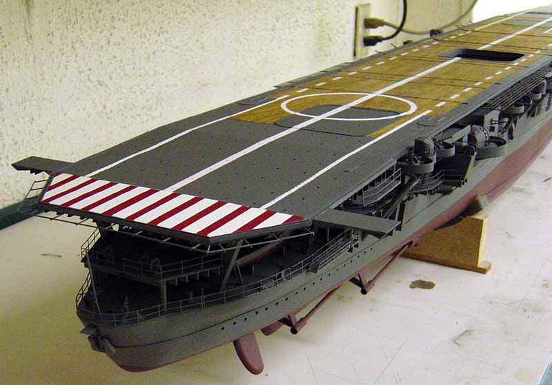 |
||||
| Well that's it for pt. 6 of the build of the Soryu. Hope
you all enjoy the photos. I must apologize again for the lack of detailed
construction methods but I am under the gun on this one!! I have 5 weeks
left to complete the project and I will make it!! Pt. 7 will be the bridge
construction then final assembly. of the ship. Stay tuned!! Thanks again
to the staff at Modelwarships.com. without whom this would not be possible
to show you all. A great forum for all of us!!!!
Any questions anyone has or if I can be of any assistance, please feel free to e-mail me at bjsww@earthlink. net. Bill
Waldorf
|
|||||
 © ModelWarships. com