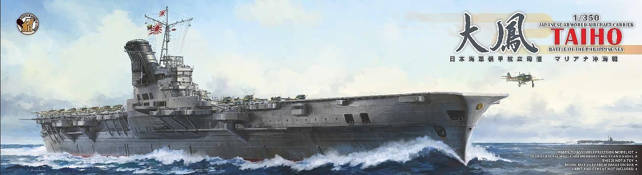
Veryfire 1/350 Japanese Armored Aircraft Carrier Taiho
Battle of the Philippine Sea
Kit # BELBV350901
| Reviewed
November 2021
by Dan Kaplan |
| HISTORY | ||||||||||
|
Background
The Imperial Japanese Navy was a dedicated believer in USN Admiral Alfred T. Mahan’s widely accepted strategic view that command of the sea determined national greatness. This view dovetailed closely with Japanese aspirations to become a modern nation-state that was the equal of Western imperialistic powers at the close of the 19th century. The decisive defeat of the Russian Baltic Fleet by the Japanese Combined Fleet at the Battle of Tushima in 1903 greatly reinforced this belief. It also ushered in several decades’ adherence by the Imperial Japanese Navy to the idea of a decisive single naval battle deciding the outcome of a war. Subsequent Japanese naval doctrine was built upon this view, with a titanic battle between fleets of battleships deciding the outcome of that war. Essentially, such a battle would have been an artillery duel between capital ships. The emergence of large, fast aircraft carriers in the 1920s did not change these views much. The aircraft carrier’s flight deck was considered quite vulnerable, and the state of naval aviation at that time did not appear to pose a great threat to capital ships. However, that was no longer the case by the mid-1930s. Naval aircraft and ordinance had evolved quickly by then, signaling a greater potential role in the outcome of a decisive battle. It was foreseen that enemy carrier-borne aircraft would eventually be able to damage or eliminate Japanese lighter forces as well as aircraft carriers and, perhaps, capital ships. Such actions could possibly thwart Japanese efforts to advance, attack and destroy an enemy fleet. Accordingly, the idea of achieving air supremacy over the battlefield prior to the decisive battle took root within Japanese naval doctrine. Various tactics were evaluated, and it became apparent
that the Japanese carriers would likely operate within the range of enemy
carriers. The necessity of delivering a heavy air strike against the enemy
early in the engagement to reduce the enemy’s ability to counter-attack
was seen as a pre-eminent requirement. To accomplish this, both the ability
to launch a sizeable strike force and to survive enemy air attacks was
deemed necessary. Large ship size and the use of an armored flight deck
were determined to be the best means to reach those goals.
Design
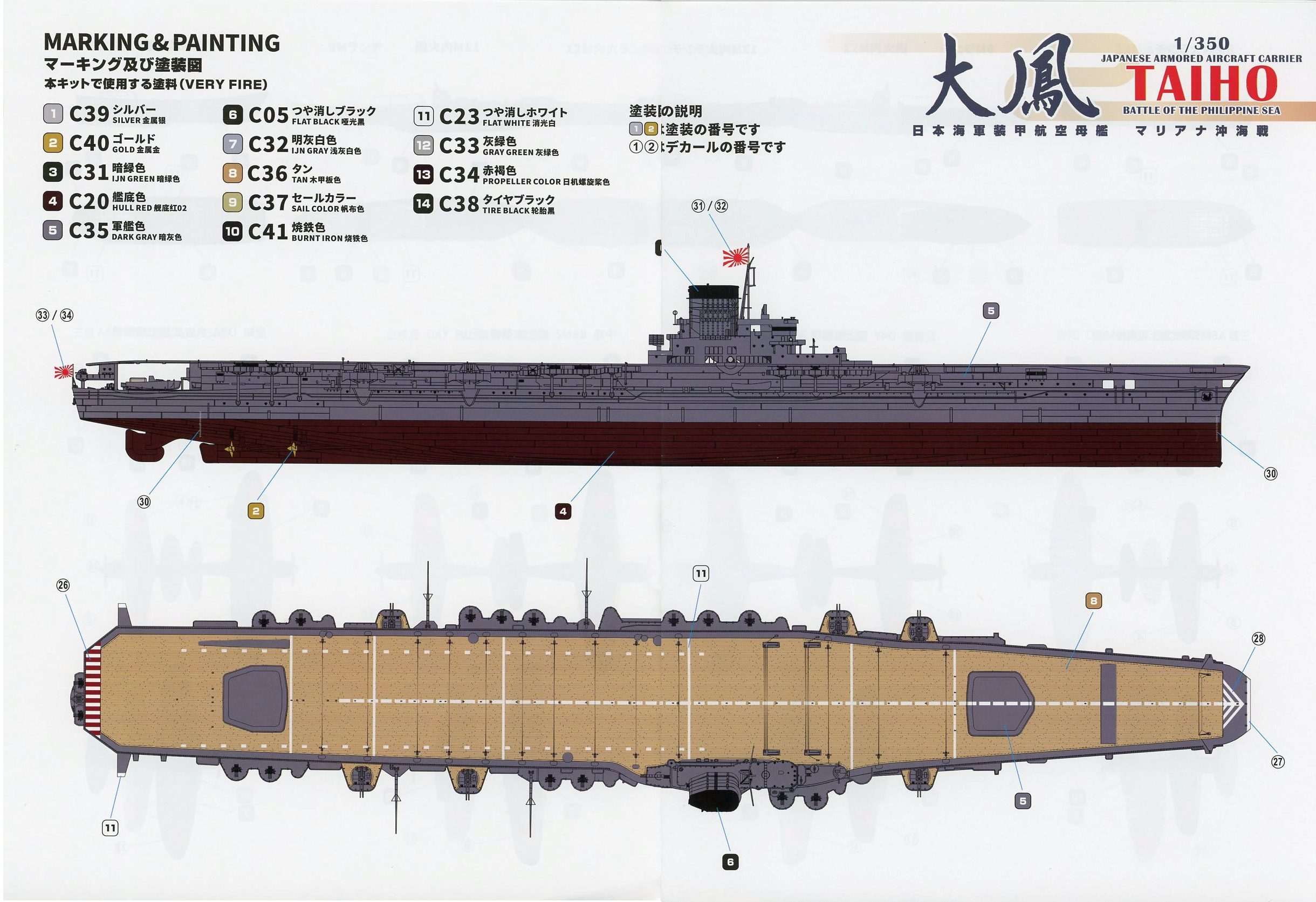
This preliminary design featured a large hull with an open forecastle, an upright funnel, an armored flight deck, two hangar decks, a length of 250m, a displacement of approximately 30,000tons, machinery producing 160,000shp to achieve a maximum speed of 33.4 kts, and a range of 10,000 nm at 18 knots. When this theoretical design reached the Basic Design and Shipbuilding Sections of the IJN’s Technical Department Bureau, it underwent much refinement and was redesignated design G-13. The armored flight deck drove the design. The requirement was for the deck to protect against armor piercing bombs of 500 kg/1100lbs. delivered by dive bombers, with additional, thicker protections for the magazines and machinery spaces. However, too much topweight would have led to a vastly unstable ship, so a number of features evolved to successfully accommodate the weight of the armored flight deck. For one, the flight deck armor itself did not cover the entirety of the flight deck. Approximately 75-80mm/3” thick, with an underlying additional layer of 20mm, it was limited to the area between the ship’s two elevators and over the double storied hangar, at a length of about 150m and width of 18m. The rest of the flight deck was simple metal plating, with wood planking over the entire surface. The flight deck itself was also shifted 2 meters to port to help counterbalance a large bridge island located on the starboard side (Important Note: for many decades, the common wisdom held that Taiho’s flight deck surface itself was not wood planked, but metal, and covered with a non-skid, latex based type of surfacing material. Based on a documented photograph of Taiho’s flight deck that emerged several years ago, along with other cues, it is now widely accepted that Taiho did, in fact, have wood planking covering her flight deck. Such a layout was the standard practice for Japanese carriers while the supply of wood was available.) Only two elevators were utilized instead of the usual three, so as to avoid a weak spot in the middle of the deck. Accordingly, these two elevators were pushed as far forward and aft as the hull contours would allow. The elevators were also armored, though not quite as heavily as the deck at 50mm thick. Still, they weighed over 100 tons each. Another substantial accommodation was the elimination of one entire deck level above the waterline as compared to the original Shokaku class design. This reduced both the structural weight of the eliminated deck and the ship’s freeboard. Eliminating the deck also meant rearranging the available internal space. This led to more compartmentation ringing around the two hangar decks. In turn, this meant utilizing a more enclosed and narrow set of hangars, thereby limiting the aircraft capacity carried below decks. Lower freeboard meant a wetter forecastle, which led to enclosing the bow in a form now known as a hurricane bow. Enclosing the bow allowed for better seakeeping, thereby avoiding damages to the forecastle and flight deck as exemplified by the experiences of carriers Hosho and Ryujo during a typhoon, now known as the Fourth Fleet Incident of 1935. It also allowed for additional crew quarters, a strengthened bow structure, and an extension of the flight deck forward. (There continues to be some debate as to whether or not Taiho’s bow form was inspired by the Royal Navy’s Illustrious class carriers, whose design and construction preceded Taiho’s by roughly two years. While entirely possible, I think that it just as likely that any such outside inspiration for the hurricane bow came from the previous Royal Navy carrier design of Ark Royal, whose bow was also enclosed and subsequently emulated by the Illustrious design.) In addition to the flight deck, the engine rooms, boiler rooms and magazines also had horizontal protection above them, varying from 40mm to 75m thick. Further, the forward and aft avgas tanks were protected from above by horizontal armor 90-100mm thick placed above them. The side belt armor was also considerable for a carrier, ranging from 2.2 inches outside the engine room and machinery spaces up to 6 inches outside the magazines and main steering. There was also a second layer of 25mm armor located 1 meter inboard of the side belt. The weight of the fully armored hull led to a deeper draft. Along with the elimination of one deck above the waterline and lower freeboard, it also meant that a portion of the pit at the bottom of the elevator shafts was now located below the waterline. Further, the bottom of the forward elevator pit was now located directly above the front of the forward av-gas fuel tank, with no appreciable void space between them. While not evident at the time, this aspect of the design would have grave ramifications given ship’s battle damage due to flooding in this area. Underwater protection was not neglected. The requirement was to resist a 300 kg bursting charge from a torpedo hit. The torpedo belt (actually a bulkhead) was composed of two armor plate layers totaling 45mm and placed 3 meters inboard of the shell of the hull. It extended from the lower edge of the side belt armor down to the outer bottom. Outside the bulkhead was a meter thick layer of fuel oil tanks, and then an air void between those tanks and the outer hull shell plating. Inboard of the torpedo bulkheads were additional, alternating layers of fuel oil tanks and air voids. Further, the ship was traditionally double-bottomed under the engineering spaces, and triple bottomed under the magazines and avgas storage. Plus, there was an armored inner layer bottom to protect the ship from mine or torpedo detonations under the keel. This protection design was a continuation of what had been used in the Shokaku class and was considered extremely robust, with a total set of layers including five plates/bulkheads and four spaces. However, this layering system lagged in one regard on Taiho – the full set of layers did not extend forward far enough to cover the forward avgas tanks. Several layers were deleted towards the bow, particularly a void space, given the narrowing contours of the hull and the need for internal space. This reduction of the layered underwater protection would also prove problematic in the instance of torpedo damage. The bridge island design was also new for a Japanese carrier. Previous designs relied on a three-story island that was typically very cramped. Taiho featured a larger, four-story island that integrated the funnel into the bridge structure. Even more radical, the funnel discharged its gases through a stack whose upper section was inclined 26* to starboard. The entire structure was situated on the starboard side, partially supported by a large hull sponson. The larger design enabled better command and communication facilities, while the angled stack swept funnel gases further away from the flight deck and allowed better airflow over the deck. A 1/100 model of the bridge had been subjected to extensive wind tunnel testing with excellent results. The same design was used in the subsequent Hiyo class carriers and Shinano. Based upon lessons learned at Midway, Taiho’s firefighting abilities were re-configured and improved over previous designs. The hangar decks were divided into a greater number of compartments by fire curtains: five on the upper deck, four on the lower hangar deck. There were also heavy, fire protection bulkheads aft the forward elevator well and forward of the aft elevator well, meant to prevent the spread of fire from the elevator well pit into the hangar deck itself. The hangar decks were divided into 18 firefighting stations, with an extensive system of foam spray and sprinkler type fire suppression arrangements running throughout the hangar decks driven by high-capacity pumps. CO2 blanketing systems were retained from previous designs as a backup. Re-routed and improved engine room ventilation was also adopted; again, based on experiences at Midway. Taiho’s defensive armament consisted of a main battery of twelve Type 98 10cm 65cal guns mounted in pairs in six semi-shielded turrets carried on sponsons on the upper hull, along with 51 Type 96 25mm AA guns contained in 17 triple mounts. The Type 98 was the successor weapon to the IJN’s standard heavy aircraft weapon, the Type 89 12.7cm 40 cal. mount. The Type 98 proved to be a very powerful and highly successful weapon. The Type 96 AA weapons was the IJN's standard small-caliber anti-aircraft weapon. The 10cm mounts were controlled by two Type 94 High Angle fire control directors, while the 25mm guns were directed by seven Type 95 fire control directors, each capable of directing the fire of up to three 25mm mounts. Her air complement varied considerably during the design phase. The combination of war experience and the planned introduction of newer, larger, more powerful aircraft meant a paring down of the number of aircraft from 78 to 53 planes. However, when she became operational, Taiho carried 65 of the current operational types. These included 22 A6M5 Zero fighters, 18 D4Y1 and 4 D4Y1-C reconnaissance model Judy dive bombers, 18 B6N2 Jill torpedo bombers, and 3 D3A2 Val dive bombers for ASW patrol. The final design specs were close to what the original specifications had laid out: a standard displacement of 30,200 tons and a full load displacement of 37, 780 tons, an overall length of 60.6m/846’11.5”, a mostly armored flight deck, a two-story hangar deck, eight Kampon boilers producing 160,000shp driving four steam turbines and four shafts for a top speed of 33.3knots, a bulbous bow to reduce water resistance, and a range of 10,000nm at 18 knots. When the design was completed, it was passed over to Kawasaki Shipbuilding. Kawasaki assigned it construction Number 130 and allocated it to their Kobe shipyard. History
In recent prior years, Kawasaki had handled the construction of both the new fleet carrier Zuikaku and the conversion of the incomplete luxury liner Izumo Maru into the carrier Hiyo. Vessel #130 was laid down on Kawasaki’s largest slipway, just as Zuikaku and Hiyo had been. In fact, Hiyo’s hull had been launched from this very slipway just two weeks prior to the laying down of Vessel #130. The original construction plan had projected launching in the fall of 1943 and completion a year later, but the demands of war dictated a faster building pace. Work proceeded briskly, and on March 5, 1943, the vessel was officially named Taiho (?? - Great Phoenix). She was launched a month later on April 7th. In early February, 1944, Taiho was moved from Kobe to the Kure Naval Arsenal for her final fitting out. She was subsequently commissioned into service on March 7, 1944 and administratively assigned to Third Fleet’s Carrier Division 1 (CarDiv 1). Training and familiarization for the crew began immediately. The core of the crew was composed of veterans transferred from other carriers, but most crewmembers were new. There was also a technical team from Kawasaki aboard to assist with any mechanical issues. Unfortunately, the dire wartime situation curtailed the amount of time that was available to spend on training. Taiho spent only three weeks working up on the Inland Sea before she was deployed to Singapore in order to join the First Mobile Fleet. She arrived at Singapore’s Seletar Naval Base on April 4th, accompanied by destroyers Hatsuzuki and Wakatsuki. The next day, she relocated to the fleet anchorage at Lingga Roads, about 100 miles south-southeast of Singapore. There, she specifically combined with fleet carriers Shokaku and Zuikaku to form the reconstituted CarDiv 1. While awaiting battle, the focus of all the IJN’s carrier groups was pilot and air crew training. The naval air battles of 1942 and 1943 had sapped much of the IJN’s experienced, carrier-qualified aircrews. That circumstance, the accelerated training of new pilots and aircrew to replace them, the introduction of new, more powerful carrier aircraft, and the decline in avgas fuel stocks made the training of fresh aircrews urgent, problematic and somewhat limited. CarDiv 1 conducted flight training for their new air crews over the next month. Their lack of experience dictated basing most of them at the land-based airfields ringing Singapore while they practiced landings and takeoffs. The carriers would also sortie frequently from the anchorage into relatively protected areas for carrier landing and takeoff practice, and to serve as targets for mock aerial attacks. On April 15th, Vice-Admiral Jisaboro Ozawa subsequently transferred his flag from Shokaku to Taiho, in part to take advantage of her more spacious command and communications facilities. On May 6th, all CarDiv1 carriers took aboard their aircraft on a permanent basis. Meanwhile, the low fuel situation for CarDiv 1 and its escorts dictated a 950+ mile move east to a new anchorage off the east coast of Borneo’s Tarakan Island. (This anchorage is located immediately to the southwest of the Tawi Tawi Island group of the Philippines, and is often referred to as the Tawi Tawi anchorage.) Mounting Japanese oil tanker losses to US submarine attacks meant that there were inadequate amounts of refined fuel oil for the fleet to use while based at Lingga Roads. The oil fields surrounding Tarakan produced a lighter fuel oil that required less refining, so it was determined that the fleet would refuel directly from available stocks there. While facilities at Tarakan included a refinery and four petroleum loading piers, there wasn’t enough refined fuel in storage to go around, so crude oil was used. Long-term use of this type of unrefined crude oil would eventually corrode ships’ boiler tubes (because of salts that are mixed in with the waters that are part of the undistilled crude), but that was considered a necessary tradeoff in order to remain operational. CarDiv1 and its escorts left Lingga Roads on the 11th and arrived at the Tawi Tawi anchorage on the 14th. There, CarDiv 1 joined there with the other elements of the First Mobile Fleet, including CarDiv 2 (Hiyo, Junyo, Ryuho) and CarDiv3 (Zuiho, Chitose, Chiyoda). CarDivs 2 & 3 had been training their new aircrews in Japanese waters. Beside access to fuel, the relocation put the fleet closer to impending operations, specifically the decisive battle plan termed Operation A-Go, the annihilation of the American fleet. However, there were some downsides to the move. The biggest was the lack of land-based airfields in the area. The relative inexperience of the aircrews made flight operations off the carriers more risky than usual. The situation was further compounded by the danger posed by US submarines ringing the area. In fact, carrier Chitose was attacked outside the anchorage on May 22nd while engaged in pilot training. (Not to mention that five Japanese destroyers were sunk in rapid succession in the same area in early to mid-June, plus two oil tankers used for UNREP.) So, flight training was curtailed and the flight crews sat idle. Their newly acquired skill sets for carrier operations deteriorated with the lack of use. Meantime, US forces were known to be massing for an invasion of yet another of the inner rings of Japanese held islands. USN carrier-based air attacks against airbases in the Marianas on June 12th, and the bombardment of Saipan on the 13th, signaled an impending invasion there and likely elsewhere in the Central Marianas Islands chain. With battle imminent, the decision was made to move the Japanese fleet again, to a new anchorage 600 miles to the northeast off Guimaras Island in the Central Philippines. Doing so would give the fleet one last fueling stop as well as a chance for the aircrews to brush up their skills using airbases there. That same day, the First Mobile Fleet left for Guimaras Island. Pilot training and ASW patrols were immediately resumed enroute. Unfortunately, pilot inexperience led to a fatal mishap aboard Taiho. A Jill (Nakajima B6N Tenzan torpedo bomber) pilot misjudged his landing after conducting an ASW patrol. The crash and resulting fires consumed that aircraft, three Vals (used for ASW work) and two Zeros. One of the aircraft crew was killed, as was seven of the deck crew. The fleet arrived at Guimaras the next day. With the invasion of Saipan clearly looming, it was decided to implement the Japanese decisive battle plan A-GO immediately. So, there was no time to resume flight training. The fleet refueled overnight and departed for battle off Saipan and the Marianas on the 15th. The Japanese fleet was subsequently sighted that same evening by US submarines prior to passing thru the San Bernardino Strait. The First Mobile Fleet consisted of nine aircraft carriers, five battleships, eleven heavy cruisers, two light cruisers, twenty-six destroyers, a supply group of six tankers, and a scouting line of twenty-four submarines. The warships were divided into three battle groups, each built around three aircraft carriers. The group containing the three light aircraft carriers of CarDiv3 was termed the Van Force, given a heavy escort of battleships and cruisers, and placed as a vanguard force 100 miles in front of the other two groups, termed A Force (with CarDiv1) and B Force (with CarDiv2), themselves separated by approximately 15 miles. The formation had been war gamed in 1943 as part of an evaluation of the carrier battles of 1942, and was thought to provide the best chance of retaining the effectiveness of the larger fleet carriers in Force A and B. The Japanese plan of attack was to use the greater range of its aircraft while keeping their forces outside the range of American aircraft. This advantage would be bolstered by having the carrier aircraft utilize Japanese airbases in the Marianas as interim refueling and re-arming stops. These island bases were also expected to contribute their own aircraft squadrons against the American forces, thereby providing multiple avenues of attack and hopefully overwhelming the Americans. Very early in the morning of June 19th, Japanese search aircraft from Guam found the American Fleet, Task Force 58. A series of land-based attacks from Guam quickly followed, but these actions were sparse and ineffective. Shortly after the initial contact sighting, a reconnaissance plane from light cruiser Noshiro spotted the American task forces around 0630 hours and signaled the First Mobile Fleet The Japanese launched a first wave attack of 64 aircraft from the carriers of the Van Force, and then a second attack wave of 128 aircraft from CarDiv 1 (including 42 from Taiho) was launched between 0745 and 0802 hours. Taiho’s departing aircraft climbed and circled to formate when, suddenly, one of her Judys (Yokosuka D4Y Susei) plunged into the sea, detonating one of six torpedoes launched by submarine USS Albacore, which had been tracking the battle group. One of her pilots had spotted the incoming torpedoes and nobly sacrificed himself in order to save his ship. Unfortunately, his sacrifice was not enough. At 0810 hours, one torpedo managed to strike Taiho’s hull, impacting on the starboard side around frame 54, ahead of the island and in line with the forward avgas fuel tank under the forward elevator. The explosion holed Taiho’s hull, fractured the avgas fuel tank, and jammed the forward elevator in its shaft, with a Zero still aboard. However, no fire ensued from the hit. Despite the damage, Taiho appeared to weather the hit with little obvious distress. The ship had been at general quarters with all watertight doors already closed. The flooding brought her bow down approximately 5 feet while causing a slight list to starboard. A cut in speed from 28 to 26 knots and immediate counter-flooding corrected the list. She continued on course and the damage appeared limited. The most immediate problem seemed to be the condition of the forward elevator. At the time of the hit, the elevator had been in the up position and level with the flight deck. The shock from the hit caused all of the elevator counterweight cables to slacken momentarily, with the elevator first dropping slightly and then having its starboard rear cable(s) breaking free of their elevator attachments. As a result, the elevator’s port side forward remained about 1meter below the flight deck, but the aft starboard side drooped heavily downward. Weighing in at approximately 100 tons, the elevator could not be shifted back into its regular position without heavy lift equipment. Anxious to continue air operations, Adm. Ozawa ordered the elevator pit planked over with available lumber. Damage control complied, and the opening was covered over by 0920. Flight operations continued intermittently. Around 1020 hours, another small strike was launched from the decks of CarDiv 1, while CAP fighters were recycled as needed aboard Taiho. However, the damage to Taiho was more serious than initially thought. Avgas from the fractured fuel tank mixed with seawater and flooded into the elevator well situated above it. From there, very volatile gasoline fumes began to leak into the lower hangar deck and compartments aft. At some point, the lower hangar deck became unusable due to the fumes. Halting the flow of gasoline and fumes became difficult due to the need to avoid sparks. For reasons that are not entirely clear, efforts to pump out the elevator well were insufficient, nor was the leaking fuel covered by foam from the ship’s fire suppression system. Given the enclosed nature of Taiho’s hangar decks, ventilation efforts proved extremely problematic. The opening of ventilation grates in the damaged area and the use of regular air circulation pumps were ineffective. The danger was evident to all, so the ship’s general ventilation system was ordered to full by the chief damage control officer. Landing operations had resumed around noon, so whenever possible, the aft elevator was also lowered between air operation cycles in order to help vent the fumes. Porthole glass was smashed out and sections of the hull were also said to have been pierced in order to vent the fumes, but such work had to be done without causing sparks. In any case, it wasn’t enough. Around 1430 hours, with landing operations taking place, the accumulated fumes finally exploded. Historically, the ignition spark has been attributed to an overheated generator or ventilation fan motor, but that may not be the actual case. According to some eyewitnesses, four fighters and a reconnaissance aircraft had already landed when a fifth fighter landed. Some say this last fighter provided the spark (likely from its exhaust) as it taxied forward towards the already parked aircraft. The explosion occurred in the vicinity of the damaged elevator, and it might be that accumulated and saturated fumes rising through holes in the planked over elevator well caught the spark. Still other reports suggest that this fighter crashed into the parked aircraft. Regardless of the source of ignition, the force of the explosion buckled the armored flight deck forward, splitting a portion of it, and blowing out a section of the upper hull in the area of the damaged elevator. However, most of the force of the explosion was vented downward by the armored deck, rupturing the hull below the waterline. The explosion also knocked the oil lubrication pumps for the main engines offline, eliminating power. Taiho immediately began losing headway and started settling in the water with a list to port. Fires began to rage topside and forward, leading to the evacuation of the bridge. Ongoing explosions occurred at regular intervals below decks. The order to abandon ship was given around 1500 hours. Admiral Ozawa was forced to transfer with the Emperor’s portrait to destroyer Wakatsuki via small boat, and then to heavy cruiser Haguro (whose communications suite proved insufficient), and finally a third time to Zuikaku, where he resumed command of the fleet. After Ozawa’s departure, destroyers Isokaze and Hatsukaze approached Taiho’s stern and took off as many crew members as they could. Shortly after Isokaze withdrew, around 1630 hours, Taiho tilted suddenly to port, and sank by the bow. Some reports suggest she capsized, but that remains unverified. Approximately one third of her crew, 660+ men, were lost, along with 13 aircraft. Her entire service history had spanned just 3 ½ months and one operational sortie. |
||||||||||
| The
Very Fire Taiho
This is the first kit of Taiho released in 1/350 scale, from Veryfire. Veryfire is a relatively new model manufacturer, having released its first kit in 2017, but they’ve already gained a good reputation for producing highly detailed and fairly accurate kits, including new classes and designs not often covered by model makers. It’s also VeryFire’s first aircraft carrier and first Imperial Japanese Navy kit. (Editorial note: Yay!) It’s a big kit for 1/350, and it comes with a lot of sprues, forty-six in fact. The styrene part count is, by my rough count, 1106 parts, though not all are used. The kit is molded in a medium grey styrene plastic, with no obvious sinkholes or surface marring, and some hint of flash on a handful of some very small parts. The styrene is matt surfaced and on the hard side, which lends itself to the better execution of molded detail. Of which there is a lot. For those modelers concerned with accuracy, know that all of Taiho’s details are not well documented. Only a few photographs and plans exist. So, there is some conjecture and “common wisdom” about certain aspects of her construction that have arisen over the years. Veryfire has reliably followed the existing information and produced a high-quality model. They have made what I think are informed choices with regard to these uncertainties, and I will try to elaborate on such aspects as they come up, under “Rivet Counter Notes”. It’s important to remember that while IJN design and construction practices did evolve over time, they were generally consistent throughout the war, so radical departures from norms in terms of Taiho’s features was unlikely. |
||||||||||
| Sprue A - Hull | ||||||||||
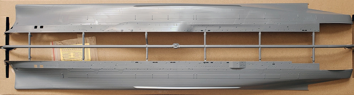
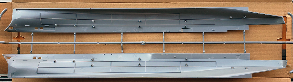
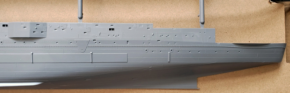
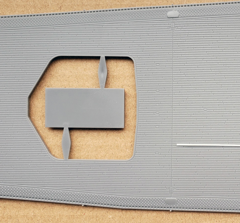
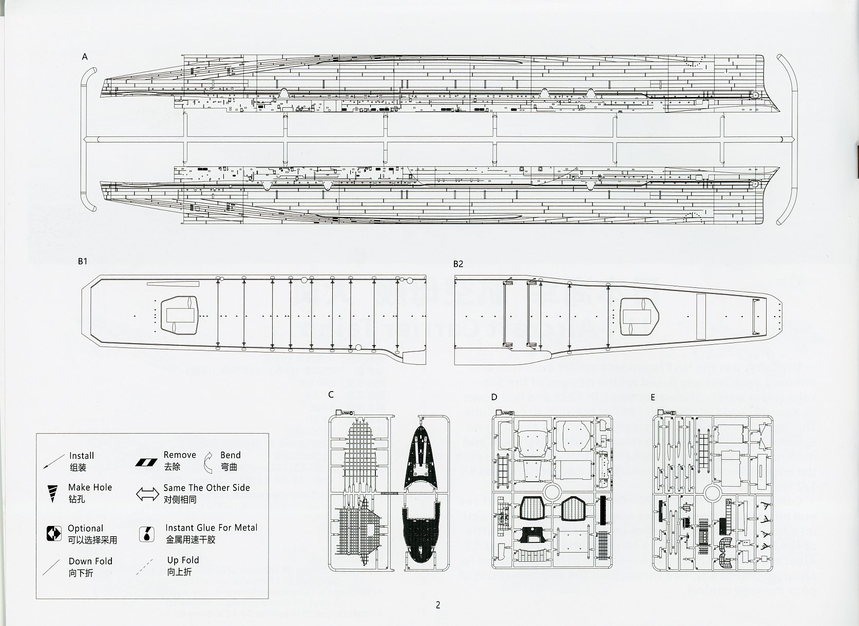
| Taiho’s hull is molded as a full hull,
split longitudinally into two halves. Very Fire seems to have taken a (smart)
page from Hasegawa in packaging the hull for its larger 1/350 kits. Each
hull half is connected to the same, very large sprue along its length,
with runner extensions for each bow and stern portion. The sprue extensions
are set into cutouts in a heavy cardboard tray that fits full length and
width into the kit box. Doing so keeps the hull halves from shifting during
transit.
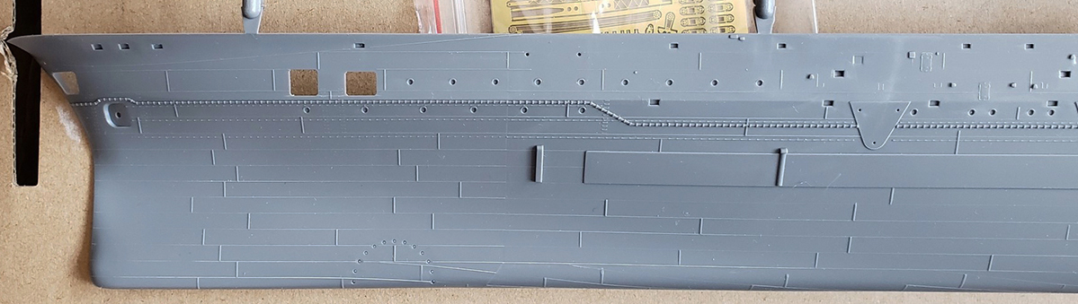
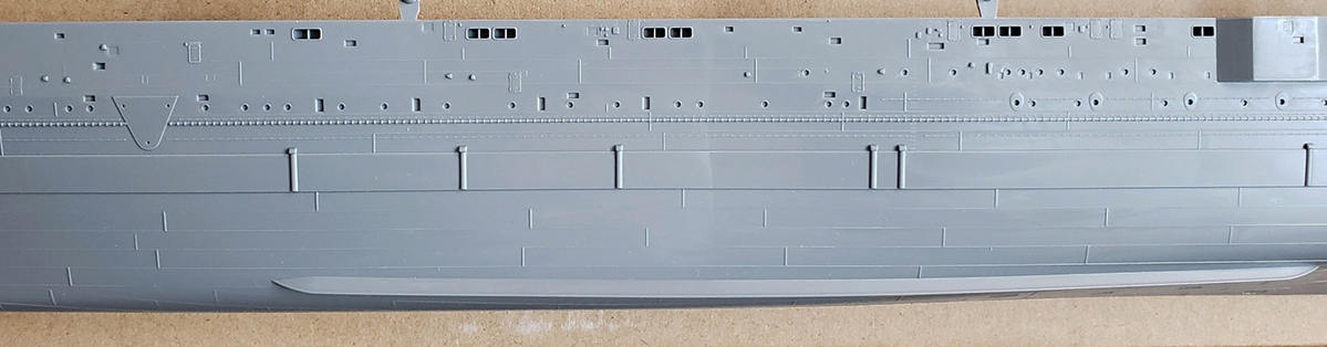
The hull itself is beautifully rendered, with extremely sharp details. There’s hull plating, and it’s depicted with subtle, thin raised lines, both horizontal and vertical. The kit’s hull walls range in thickness from 2.2mm at the sides to 2.7mm at the keel, so it’s a very stable structure even without the internal stiffeners. The details are beautifully executed and extensive. They include: recessed anchor hawseholes, portholes with eyebrows, grab rails, a degaussing cable with brackets, hull openings at the bow to the enclosed forecastle deck, a recessed sensor array for a Type 93 hydrophone placed on the bottom of the hull towards the bow, bilge keels, grated sea chests below the bilge keels by the engine rooms, small recessed air intakes with coamings and grillwork, fully detailed hatches and doors, small equipment boxes that sit above the catwalks, even smaller air intakes and vents mounted on the hull sides, a small sponson on the port side and a large one to starboard that helped support the island, waste discharge pipes, and a waterline belt armor. Plus, the mounting points for sponson/catwalk supports as well as the propeller shafts and brackets. Fortuitously for waterline fans, Very Fire has seen fit to mold a horizontal slot in the inside of each hull half denoting the actual waterline. Though there is no corresponding waterline plate included, the slot provides a handy guide for cutting the hull down to its waterline configuration for those who prefer this configuration. Adding a waterline plate, either hidden or visible, will require some scratch-building. To further aid such an effort, VF has positioned most of the mounting points for the internal hull stiffeners above the waterline. Nitpicks are minimal. The hull plating pattern is hypothetical, but it does follow general IJN construction patterns for large ships. Likewise, a shallow, external armored torpedo belt is depicted, but it’s debatable as to whether or not the belt would have been visible. There exists no specific information about its actual appearance. My understanding is that it was an internal arrangement. Still, given the uncertainty about the belt, it’s not worth trying to eliminate it. Visually, it works within the context of the plating. The hull scales out near perfectly. Taiho’s particulars
versus the scale and kit:
(Rivet counter notes on the external degaussing cable: Virtually of the IJN’s major combatants were equipped with external degaussing cables to counter magnetic mines, beginning in late 1941. Most large combatants typically wore their cables until their demise or surrender, but the ineffectiveness of Japanese degaussing cables became apparent by 1943, and the new installation of such cables was mostly discontinued. So, by late 1943, new warship construction typically excluded these cables. Examples include the light cruiser Oyodo, the Unryu class carriers, and the Matsu/Tachibana class destroyers. Likewise, warships undergoing major rebuilding, such as the light cruiser Isuzu, had their cables removed. Yet, oddly enough, there were also notable exceptions this trend with other new construction such as the later members of both the Agano class light cruisers and the Akizuki class destroyers. It remains an open question as to whether or not Taiho actually wore an external degaussing cable. There are no known close-up photographs of her hull to establish their presence or not. Post-war sketches of Taiho made by noted IJN constructor and historian Shizuo Fukui do not show a cable. Still, the common wisdom has been to depict the cable, as Very Fire has so nicely done.) |
||||||||||
|
||||||||||
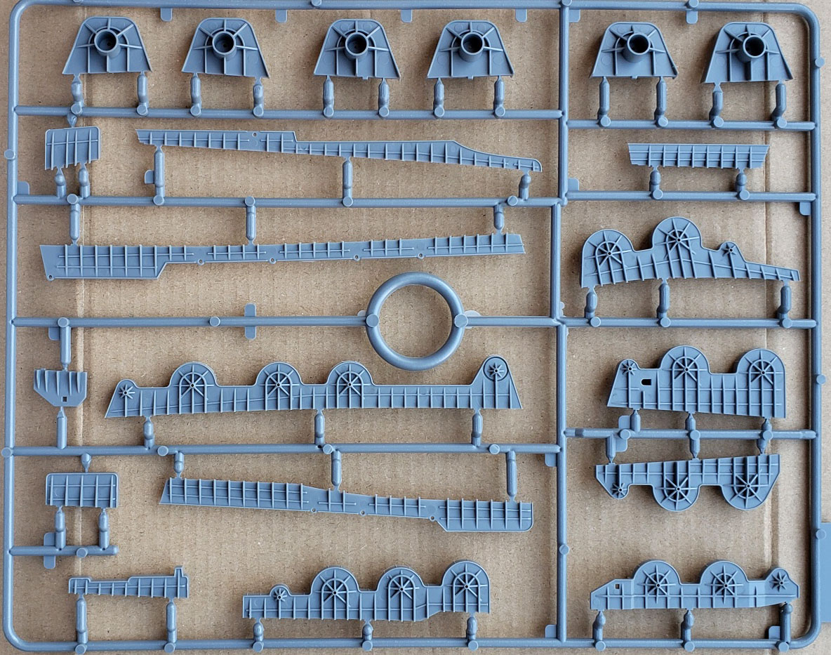
| Sprues B1 & B2 - Flight Deck | ||||||||||
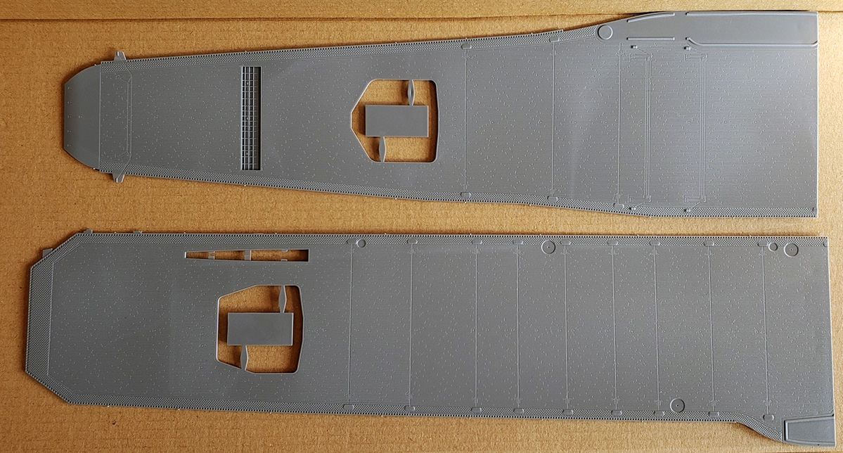
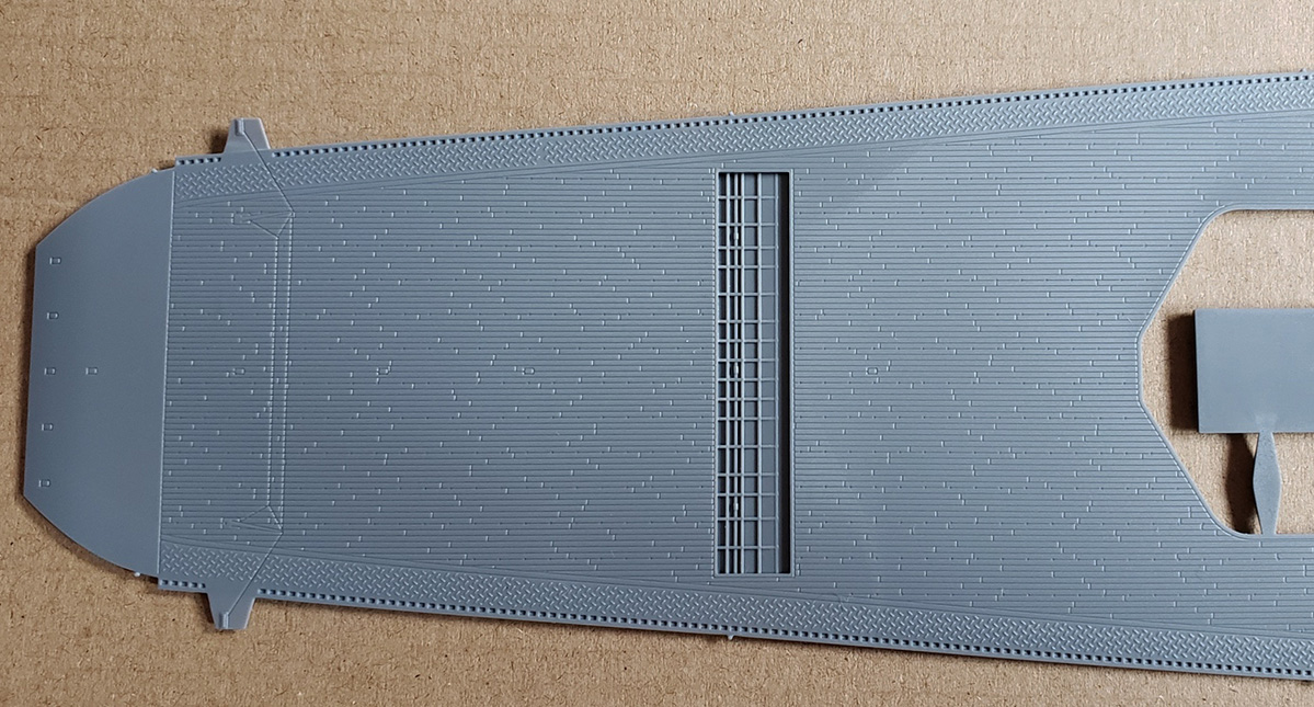
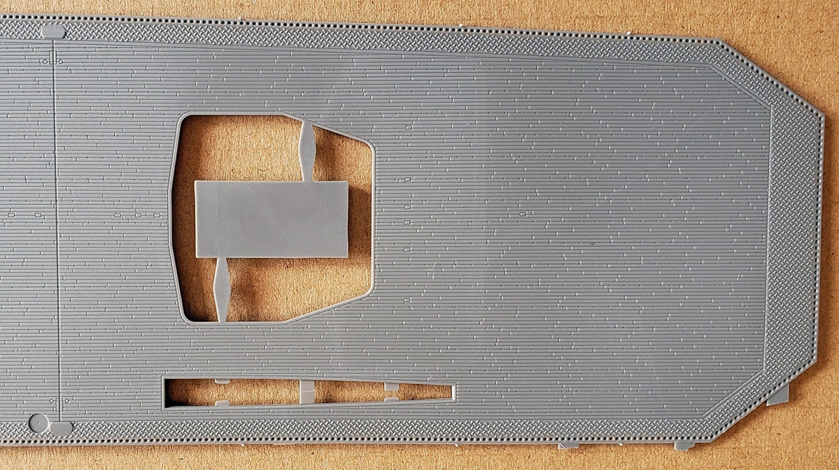
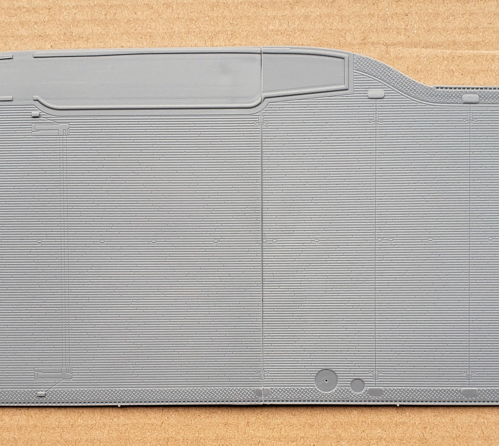
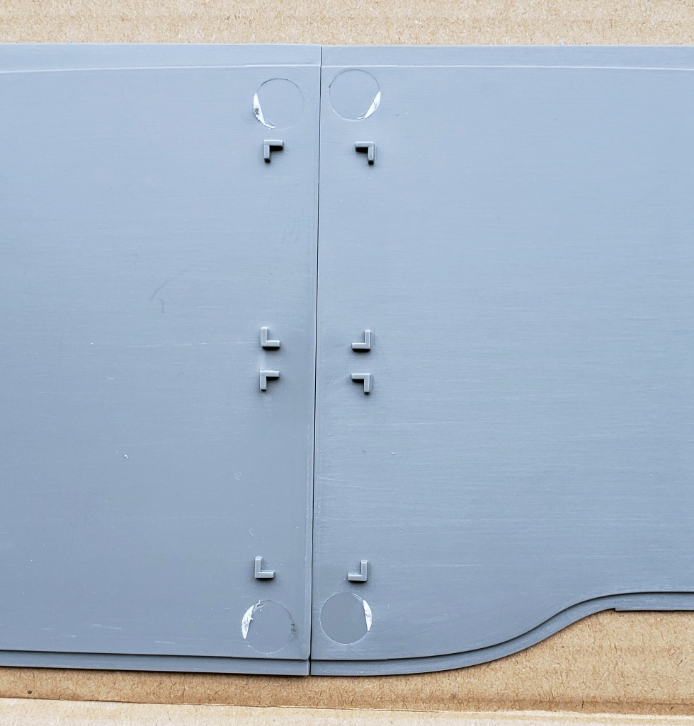
| The flight deck comes in two large,
adjoining sections. Each portion is predominantly wood planked, with metal
treaded plate and rain runoff gutters at the edges. The bow portion also
has some metal plated surfacing at its extreme end.
While a two-part deck might raise concerns regarding a noticeable seam, Very Fire has very intelligently located the joint seam under one of the mid-deck arrestor cables. Each arrestor cable rests in a shallow channel stretching cross-wise across the flight deck, so the joint seam merely mimics the channel. The actual channel extends from the metal deck edge treading on the port side to the base of the bridge to starboard. The seam disappears under the bridge, so very little of the seam is exposed on either side. It’s a smart solution. The joint surfaces between the two sections are squared off, but could benefit from a few passes with a rigid, flat sanding stick to minimize any gapping, particularly towards the middle. (My review kit shows the slightest gap between them when placed together.) The joint seam between the sections is reinforced from below with two small, flat styrene plates that are set into position and glued to both sections. A recommendation: I suppose it might depend on the glue one uses, but I would suggest gluing the connecting pieces to the bottom of the flight deck and running another bead on the underside only after they’ve been joined together. Doing so might minimize any glue bubbling up from the joint and possibly marring the arrestor cable channel’s appearance, The flight deck itself is wonderful executed. The planking width is 0.02 inches, which equates to a 1/350 scale width of 7 inches. Which means the deck planking width is scaled correctly. (See the comparison photo - flight deck vs. 0.02inch styrene strip.) The planks are separated by a very thin, recessed seam and have butt ends. The planks are laid out in a pattern that is not overly repetitive, making their appearance far more realistic than attempts by most other manufacturers of IJN carriers. Aside from the planking and rain gutters, detailing on the flight deck includes the large recessed box (with molded structural cross-members) that supported the fold-down wind barrier set into the flight deck ahead of elevator number one, subtle depressions for the aircraft tie-down holes, debossed small boxes denoting deck strip lighting for night-time operations, recessed channels for both the thirteen arrestor cables and the two wire cabled cross-deck crash barriers, embossed plates for the arrestor cables and crash barriers, recessed openings for hide-away 110cm searchlights, and small platform extensions along the deck edge for smaller lights denoting the flight deck perimeter at night. There are also large apertures for the two elevators and one for the collapsible aircraft handling crane. That Veryfire made the effort to properly mold channels for the arrestor cables and safety barriers are most remarkable. Also noteworthy is that the edge of the portion of the underside of the flight deck that fits within the perimeter of the hull sides is deep and pronounced. This ensures a proper fit within the hull. This aspect contrasts greatly with the Japanese carrier kits from Fujimi. Their edges are shallow and makes the fit problematic. The only nitpick is the size of the aircraft tie-down holes. These are on the small side for this scale and barely visible. Still, they do exist here, unlike with some other 1/350 aircraft carrier kits. Though very tedious, some enlargement with a mini drill bit wouldn’t hurt. (For rivet counters, the actual tie-down openings were approximately 100mm/4” across. In 1/350 scale, that works out to 0.01”. A bit in the mid-80s size range will work.) As with the hull, the flight deck is true to scale. Actual versus scale and kit dimensions:
|
||||||||||
|
||||||||||
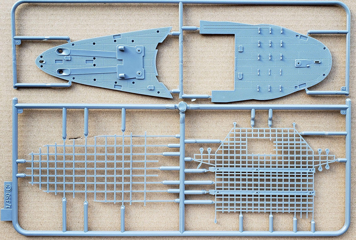
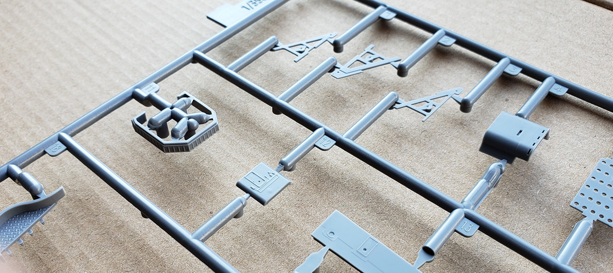
| Sprue C | ||||||||||
| Consisting of only four large pieces,
two of them are the girder support structures that underlie the bow and
stern portions of the flight deck that sit above the anchor and boat decks.
They are molded separately so as to give the modeler the option to replace
them with photo etch brass versions that are included with Very Fire’s
Detail Up Super Set A for Taiho accessory set, which must be purchased
separately.
The other two pieces are the anchor and boat decks. Both are first-rate examples of sharp, detailed molding. Both have treaded metal decking and seam lines, chaffing plates, bases for capstans, hawseholes, detailed deck hatches, and slots for mooring bits and hawser reels. Boat chocks line the boat deck. The capstan and hawsehole on the boat deck are more logically located in comparison to the relatively recent Fujimi 1/700 Taiho kit. The boat deck is one area where sparse documentation gives rise to a small issue. In addition to storing ship’s boats on this deck, Very Fire correctly provides for the starboard side boat storage tunnel that extends forward into the hull from the boat deck. They have also provided channels for a set of deck rails, similar to those used by an aircraft or torpedo trolley, and meant to move the additional boats forward and back on boat trolleys riding on these rails. (PE rails are included with the same Super Set A.) However, Very Fire has also molded a set of boats chocks that interferes with movement along those rails. In my opinion, these need to be removed and the rails extended back towards the stern so that any craft placed here could be lifted by the overhead boat cranes. For that matter, the rails should be angled inboard a tiny bit. This is really all just a nitpick, and easily correctable, if so desired. |
||||||||||
|
||||||||||
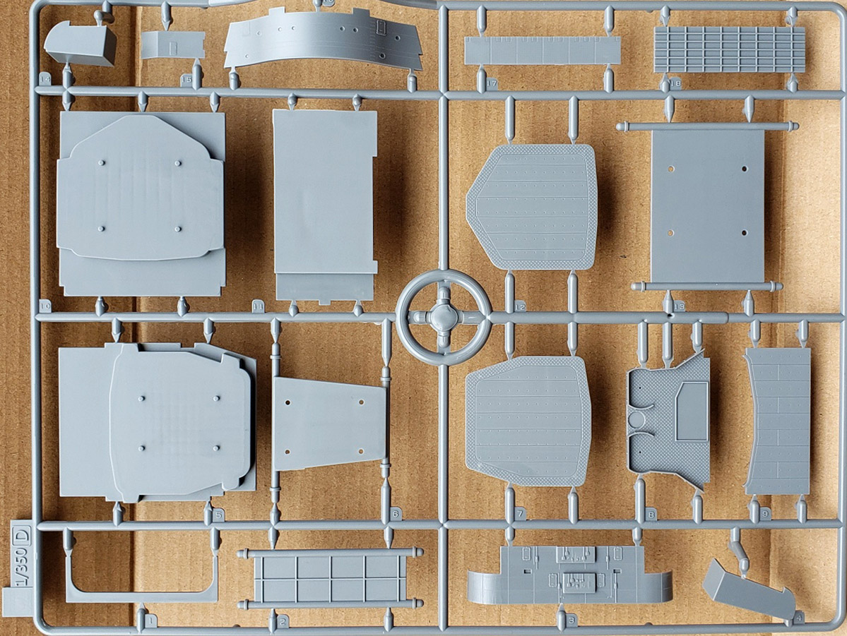
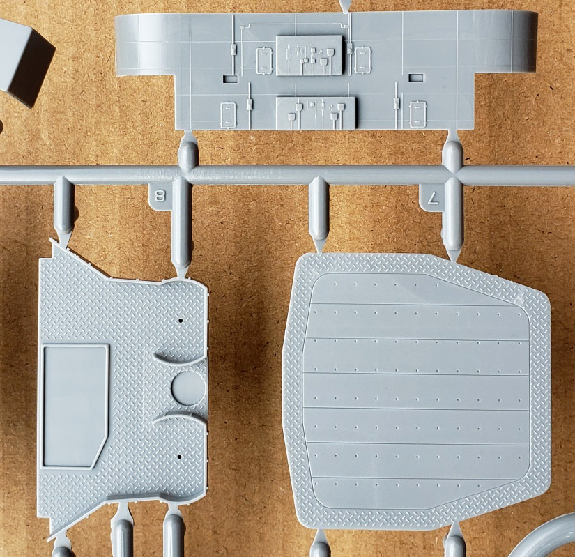
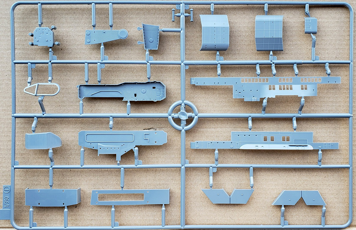
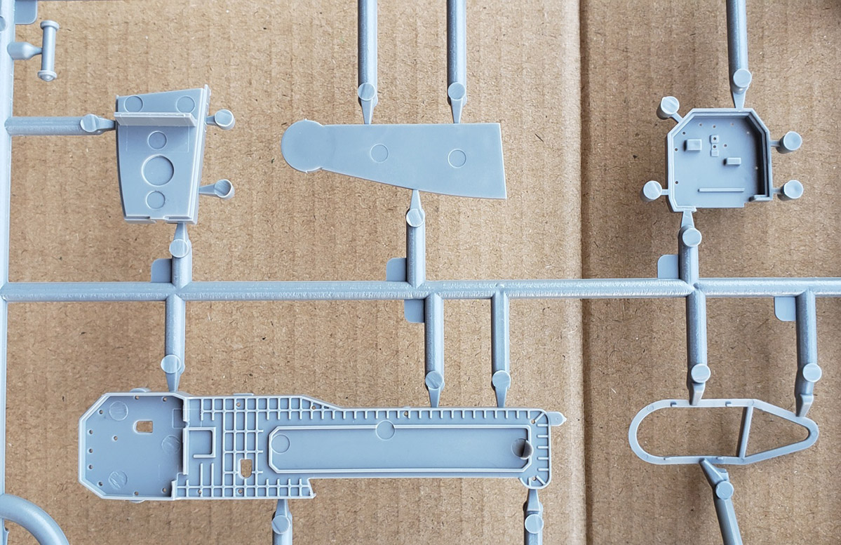
| Sprue D | ||||||||||
| A large component sprue, it holds:
several internal hull stiffeners, both aircraft elevators and both elevator
shaft bottoms, an elevator well sidewall for the bow elevator, the forecastle
bulkhead, the aft bulkhead for the hangar decks that overlooks the boat
deck, the aft AA platform that sits over the stern portion of the boat
deck, some bulkhead sections that tie-in with the aft bulkhead over the
boat deck, and some other related bulkheads.
The detailing is superb and sharp. The elevators have plating lines, tie-down holes and treaded edges, the AA platform has ribbed splinter shielding and treaded decking, the elevator well sidewall has counterweights and counterweight channels, along with molded cables for the counterweights (a nice touch). The aft bulkhead has fully detailed hatches, equipment boxes with cabling and electrical conduits and plating lines. The exposed bulkhead surfaces have trusswork. It all looks wonderful. |
||||||||||
|
||||||||||
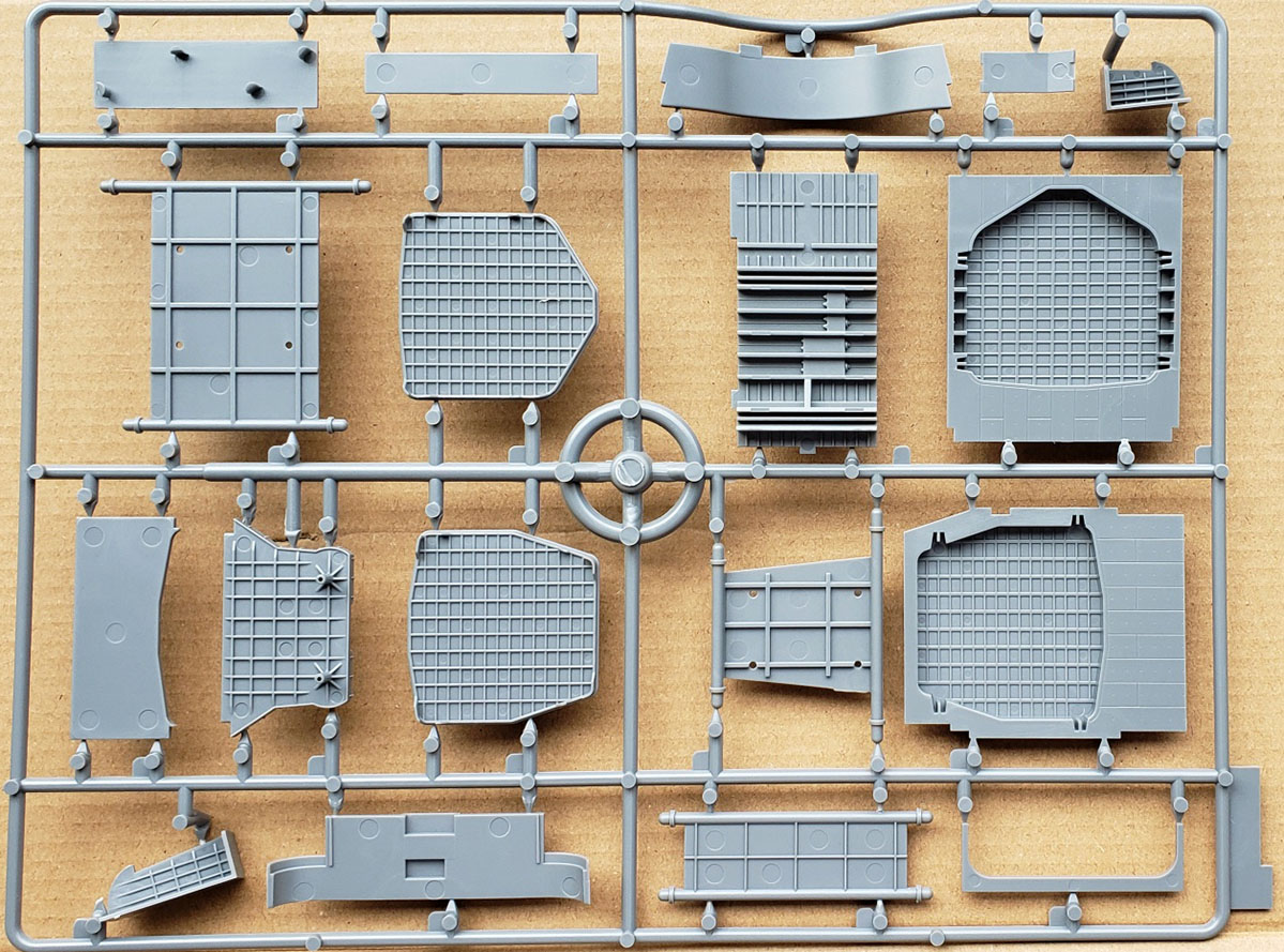
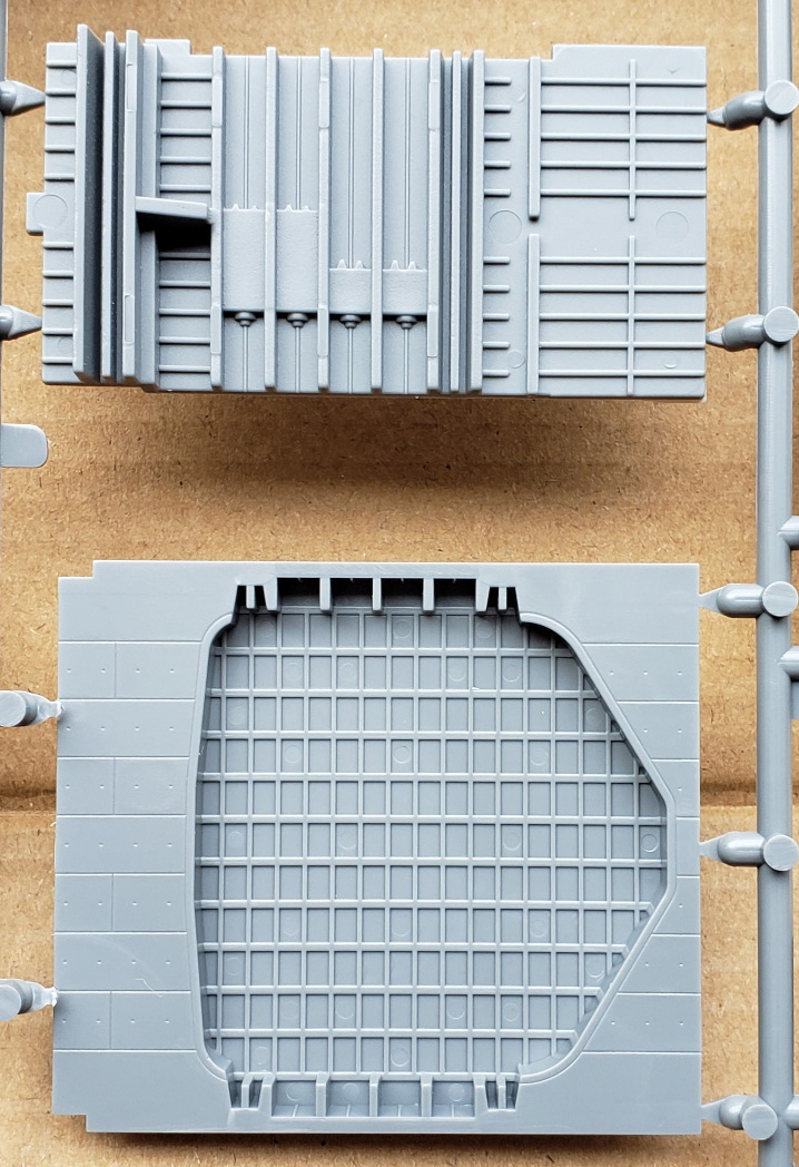
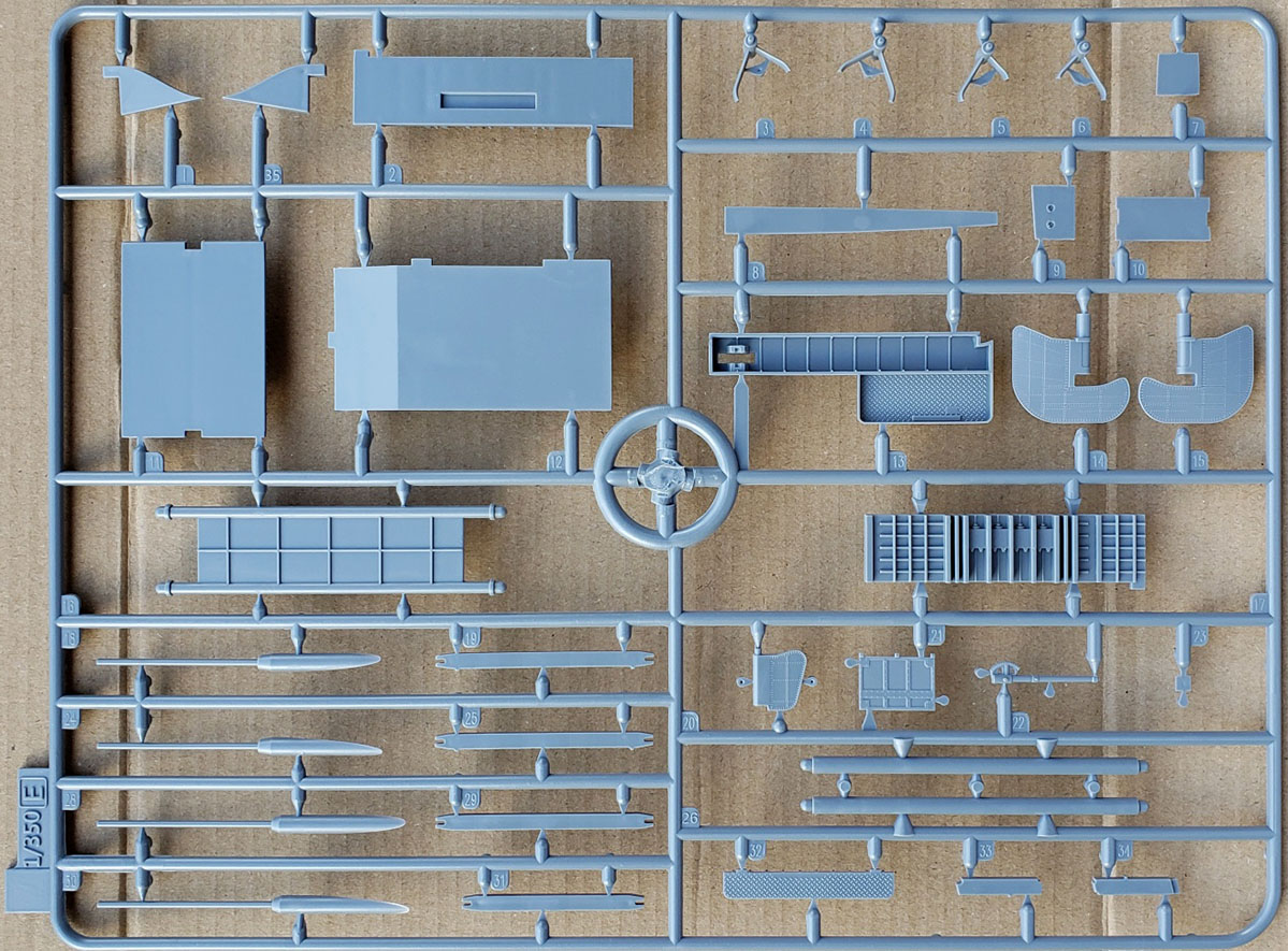
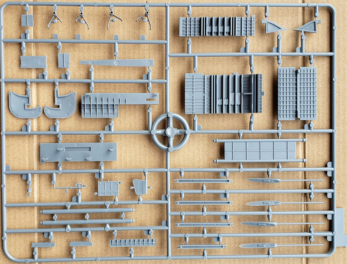
| Sprue E | ||||||||||
| Here, one finds the propeller shafts
and propeller shaft brackets, all the parts to the main and secondary rudders,
more internal hull stiffeners, the two support columns for the aft end
of the flight deck, some bulkheads for the crew’s rest quarters on the
stern AA deck, an emergency rudder, a platform for the boat deck, the remaining
three elevator well sidewalls, the girders that the elevators rest on,
a gallery sponson for the aft starboard end of the flight deck, and the
collapsible boat crane’s mast and gearing.
Ditto my comments on quality for Sprue D. The riveting and seam lines on the rudders is notable. |
||||||||||
|
||||||||||
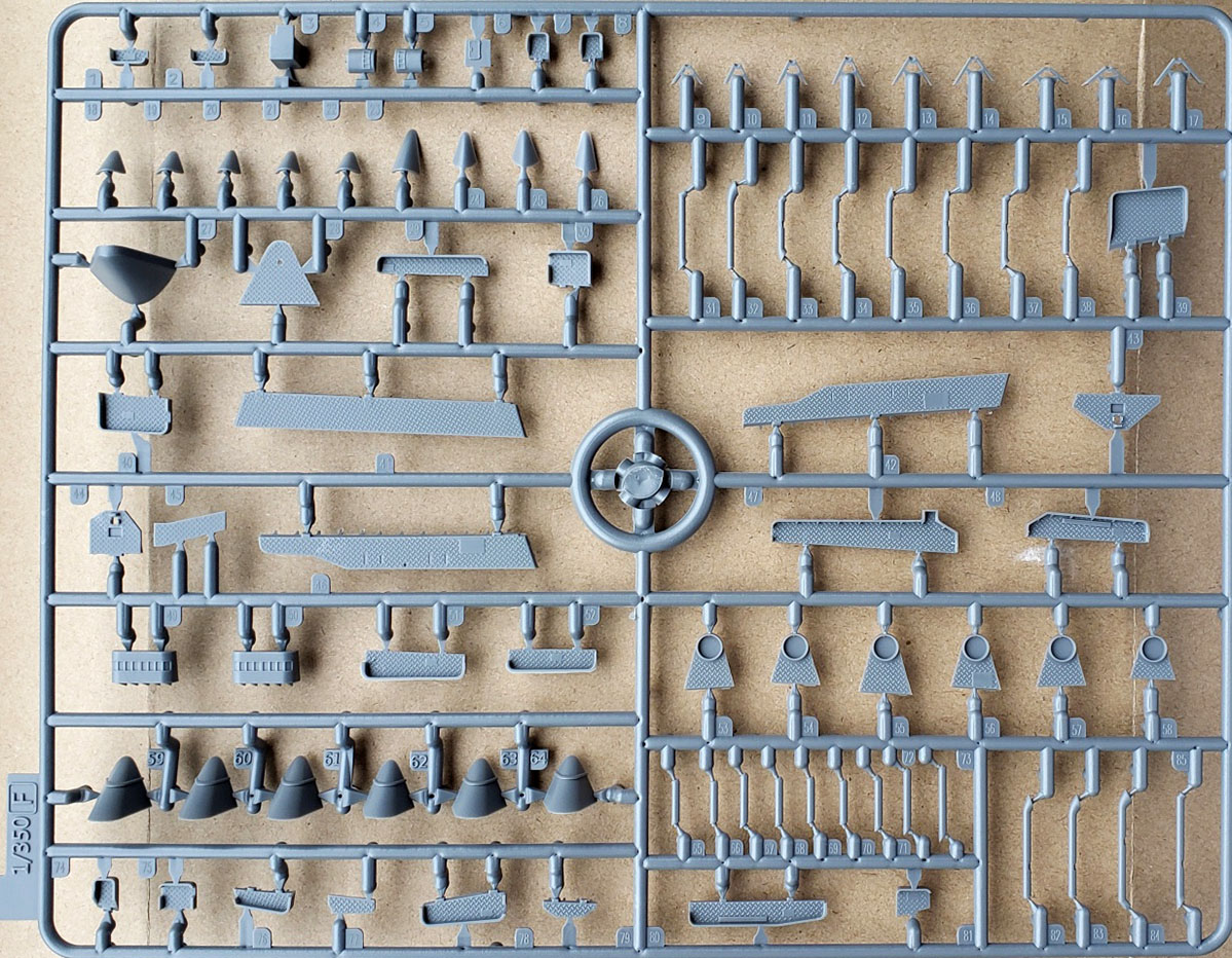
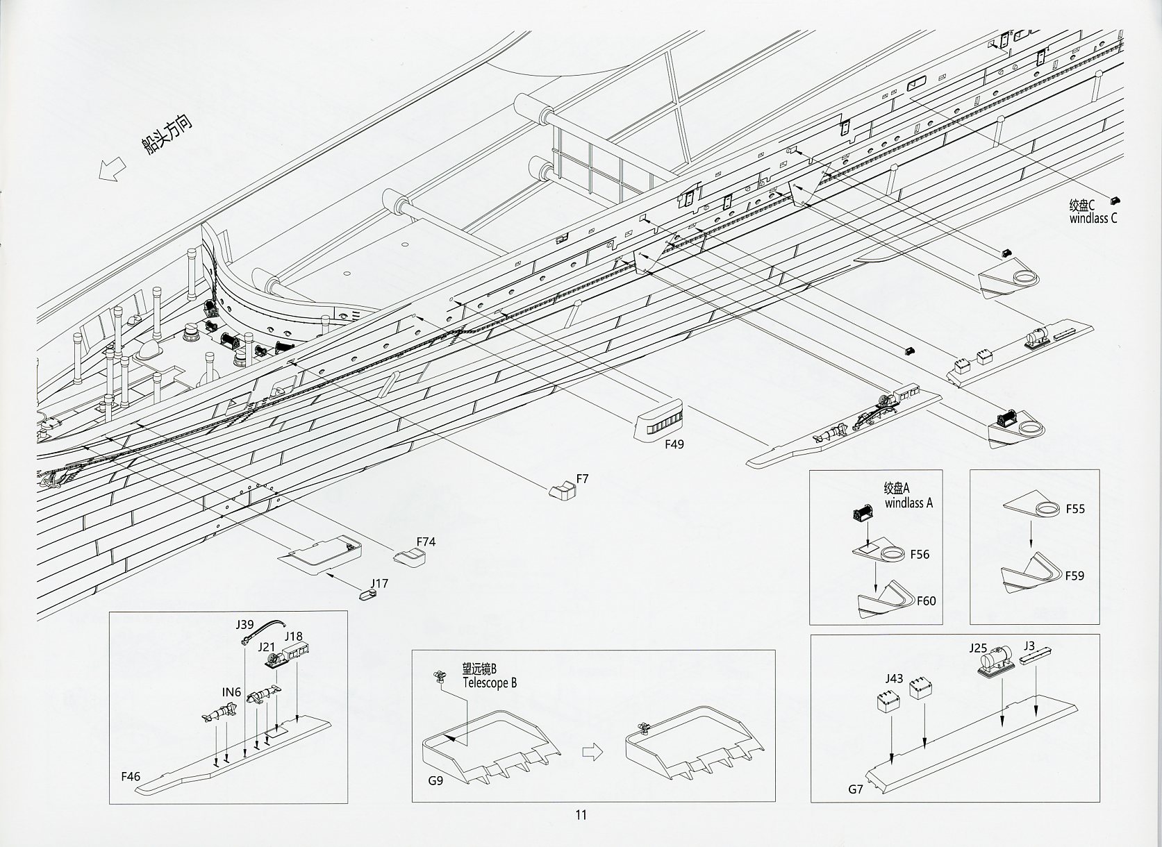
| Sprue F | ||||||||||
| This runner holds small sponsons and
catwalks. These particular catwalks are the shorter platforms that ring
the flight deck and used for flight deck personnel as well as hold related
equipment, such as landing lights, paravanes, winches, etc. Additionally,
there are the angled catwalk support columns and small blistered hull sponsons
that anchor the supports, support bracing for the same, and larger sponson
supports for the main batteries. Plus, the ship’s hull mounted navigation
and lookout positions.
Everything is uniformly crisp in appearance. |
||||||||||
|
||||||||||
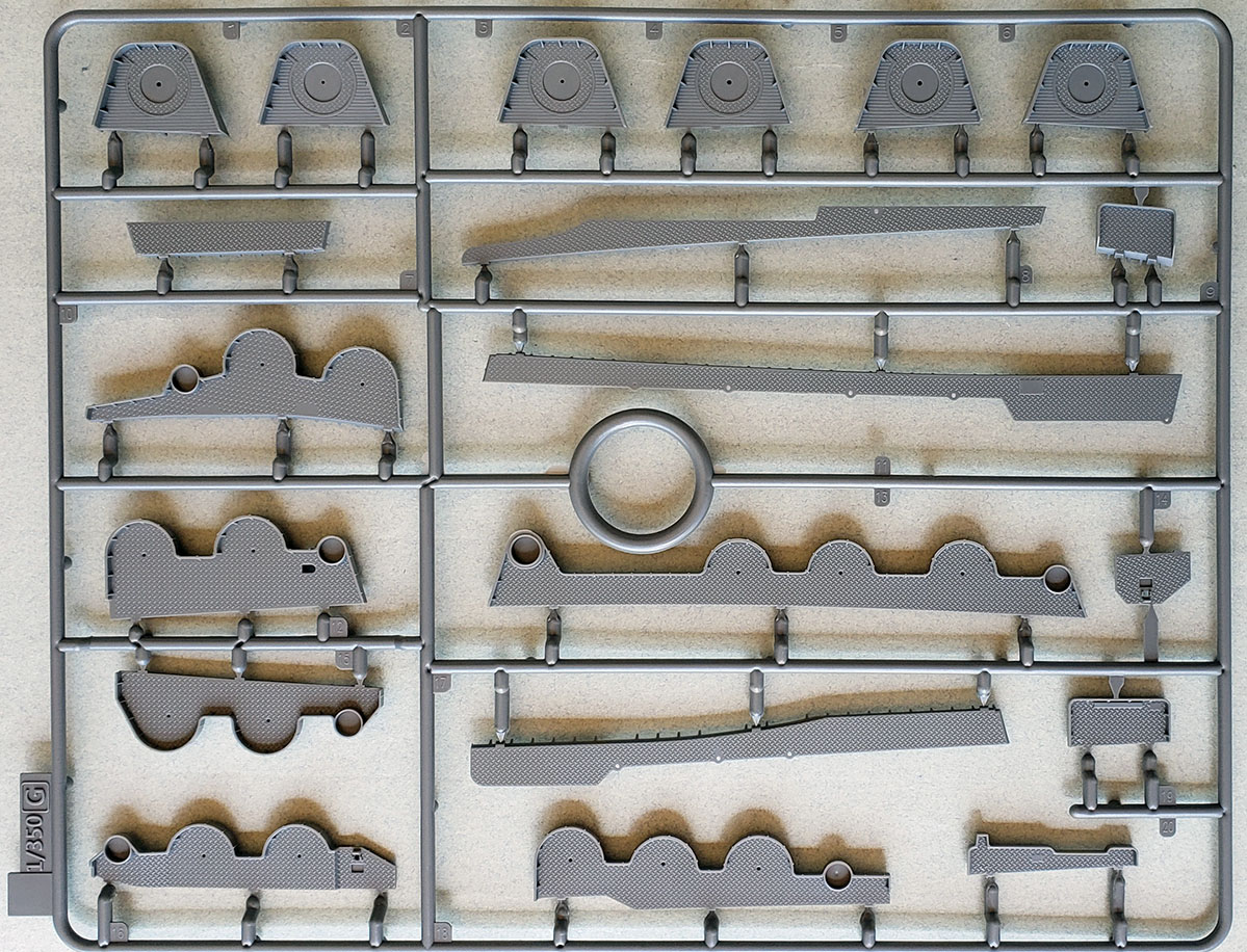
| Sprue G | ||||||||||
| This is the “large sponson”
sprue. There are three types: individual for each of the main battery 10cm
twin mounts, ones for the triple 25mm AA mounts with their AA directors,
and light catwalks. The main battery and 25mm sponsons have raised splinter
shield sides supported by ribbing, while the main mount versions also have
wood planked decks surrounding the main mount base ring. The others are
covered with replicated treaded metal surfaces. The treading is very sharply
detailed.
The undersides have extensive girder supports molded on. (The Super Set A for Taiho has a photoetch fret of brass truss supports with lightening holes to use as replacements.) |
||||||||||
|
||||||||||
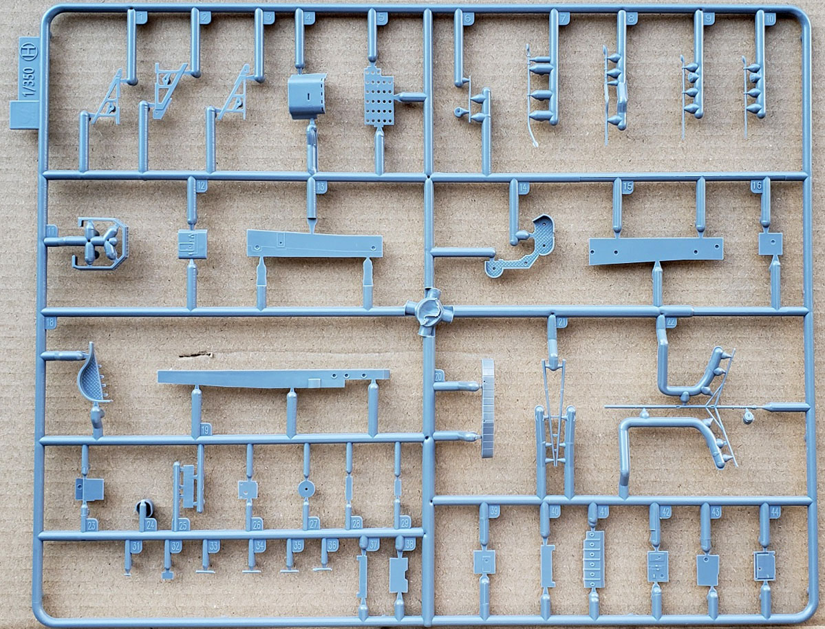
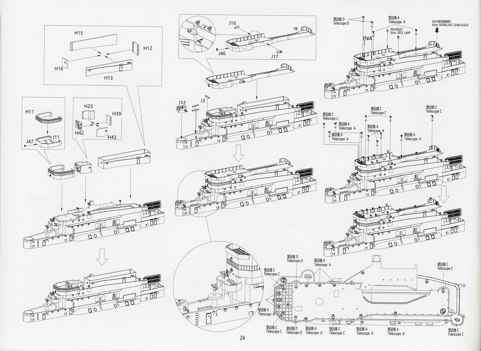
| Sprue H | ||||||||||
| This is a sizable sprue that holds
components for the bridge island. Among the components are the bulkhead
for the armored conning tower, the actual deck for the compass bridge deck
level, the bridge windows, the funnel portion for that same deck, some
bulkheads, the mainmast and tripod support legs, some of the structural
supports for the angled funnel, auxiliary piping for the funnel, some bridge
catwalk supports, a small windbreak, and some compartment bulkheads.
All details are sharp and crisply executed. As elsewhere, bulkheads have cabling and storage boxes molded on, seam lines, and the decking has metal treading. |
||||||||||
|
||||||||||
| Sprue I | ||||||||||
| Also dedicated the bridge island,
this sprue runner holds the major decks and bulkheads of the lower bridge,
some connectors, the funnel, a funnel grill ring, the AA command deck,
the funnel uptakes, and some associated pieces. All the pieces appear crisply
molded. There’s lots of nice detail on the bulkheads, treading and ribbed
splinter shielding on the exposed decks, and a nicely formed wind baffle
molded to the front face of the AA command deck.
Unexpectedly, there’s no molded funnel grill. One either has to obtain the PE Super Set A for Taiho for a brass version, use a 3D printed version sold by Beaver Corp for this kit, or make one out of brass mesh or styrene. |
||||||||||
|
||||||||||
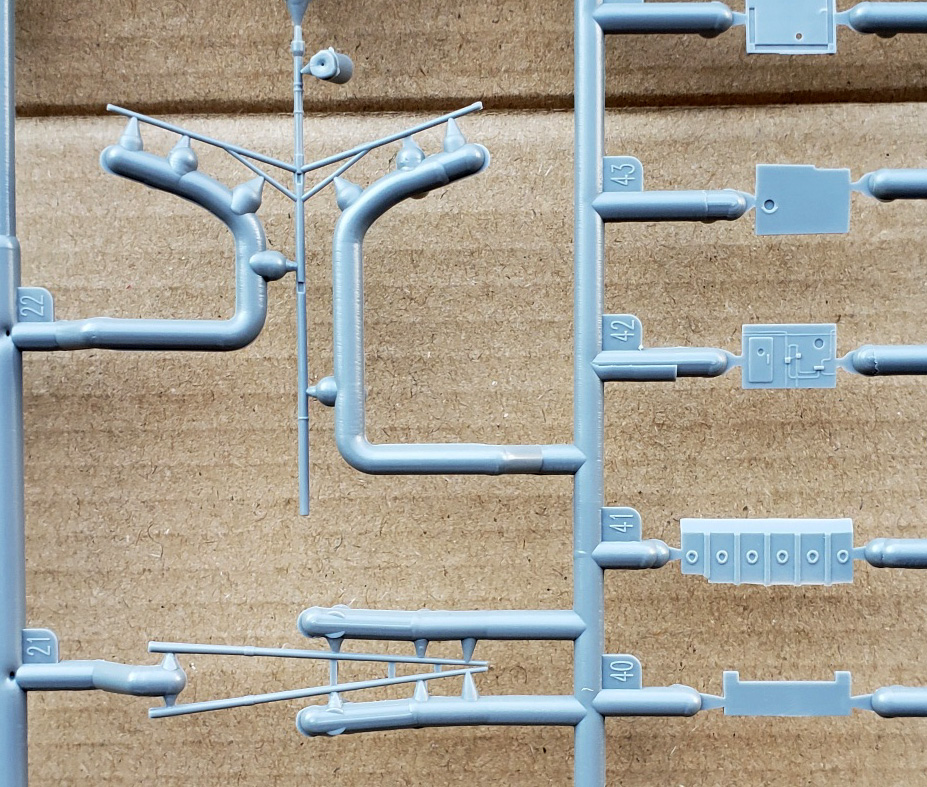
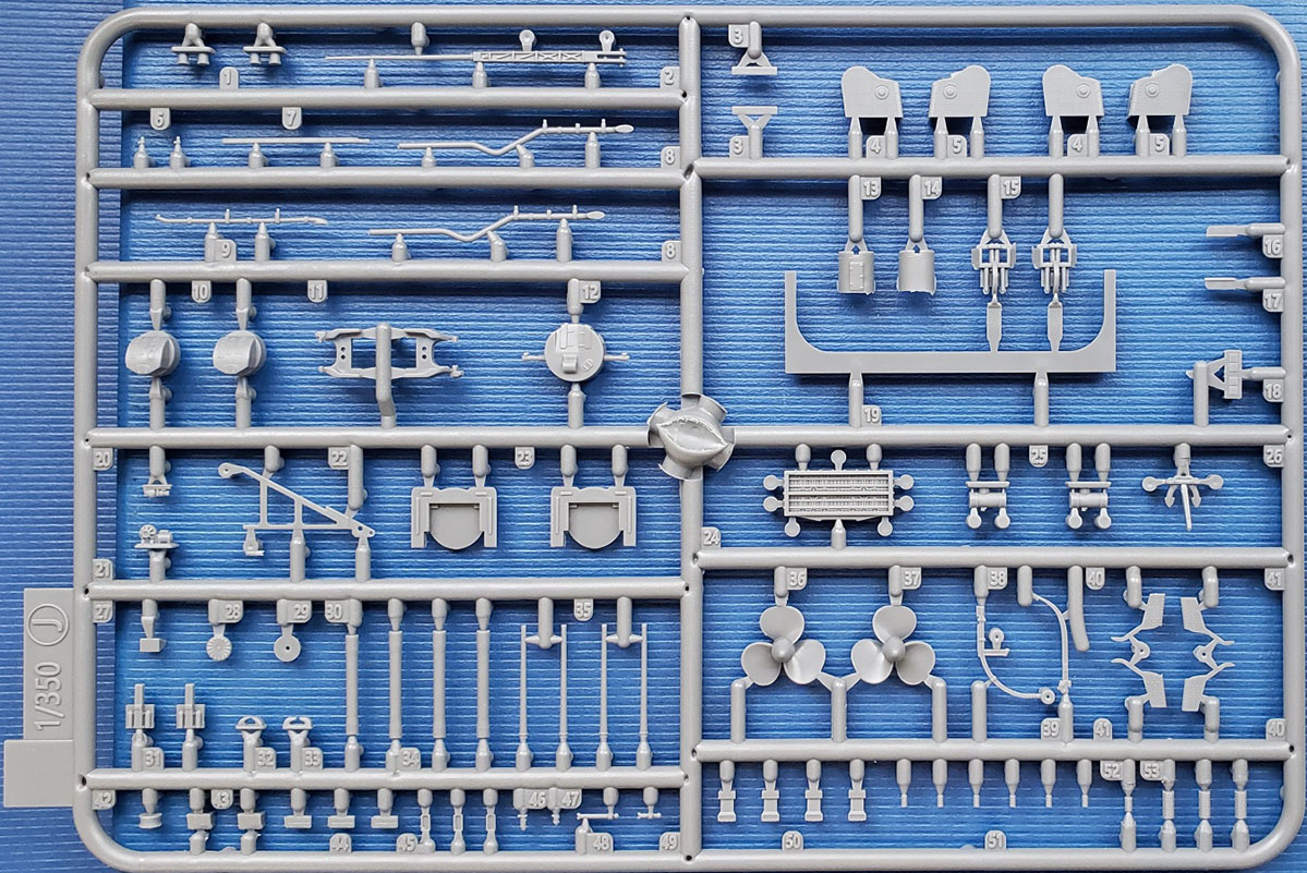
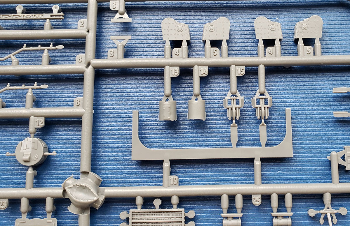
| Sprue J x 4 | ||||||||||
| Attached are all the components (eleven)
to each of two of the 10cm65cal main guns, multiple bollards, multiple
fairleads, two-piece bow capstans, a main anchor, a Type 94 HA director
for the main batteries, two enclosed 25mm AA directors, the two halves
to the base support for the Type 21 radar, one Type 21 radar, the gold
chrysanthemum for the bow, two propellers (each canted in opposite directions),
three sizes of reels (with molded coils) for the hawser reels, davits for
paravane handling, deck winches for the paravanes, port and starboard navigation
lights, small equipment boxes for the various catwalks, large flight deck
illumination lights for night time operations, one of the tall aerial masts
with attendant equipment (housing, elevation motor), two types of auxiliary
piping for the funnel, a triangular truss support for the funnel, and forecastle
column supports (two types) for the flight deck .
There’s some very nice, sharp detailing on the parts, particularly the directors and gun mounts though, unusually, there is some flash on a handful of parts on this sprue. The 10cm65cal barrels are nicely shaped and the latticework base for the radio mast is deeply molded. Likewise, the Type 21 radar also has excellent detailing, though this is one piece that would benefit from using a photoetch replacement. I suppose it’s also worth mentioning that there will be a lot of spare parts for some of these items, given the four identical sprues. Still another unexpected omission is the lack of a yardarm for the radio aerial mast. As with other such omissions, one can find the suitable components as part of the Super Set A. Or, make on from styrene rod, or source a photoetch mast from another aftermarket supplier such as Flyhawk. At this point, one could reasonably conclude that all of these detail omissions are not so subtle incentives for the modeler to purchase the Super Set A to help build the kit. On a different note, I would call into question is the need for column supports to be placed upon the anchor deck to reinforce the flight deck. This feature seems borrowed from the 1/700 Fujimi Taiho kit and is of very questionable accuracy. Plans for Taiho, including the postwar USN NavTech drawings, all show a deck of compartmentation containing workshops and stores above the open anchor deck without column supports. The installation of these columns is probably a moot point. Factual existence aside, there are a few small hull openings onto the anchor deck, and it seems unlikely that much detail will be seen there. Modeler’s choice. |
||||||||||
|
||||||||||
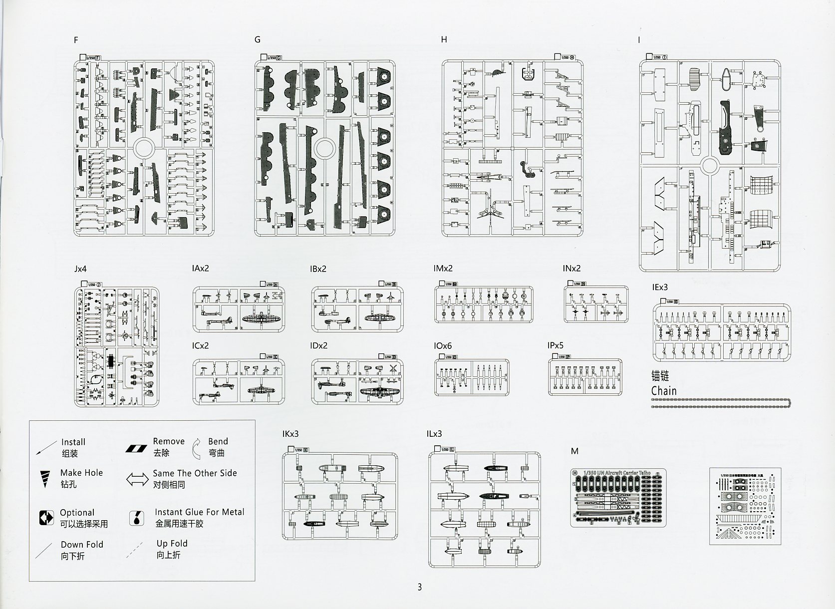
| IE Sprue series | ||||||||||
| Aside from the sprues dedicated to
the ship, there is an entire series of generalized IJN equipment sprues,
each marked by a two-letter designation starting with the letter “I”. The
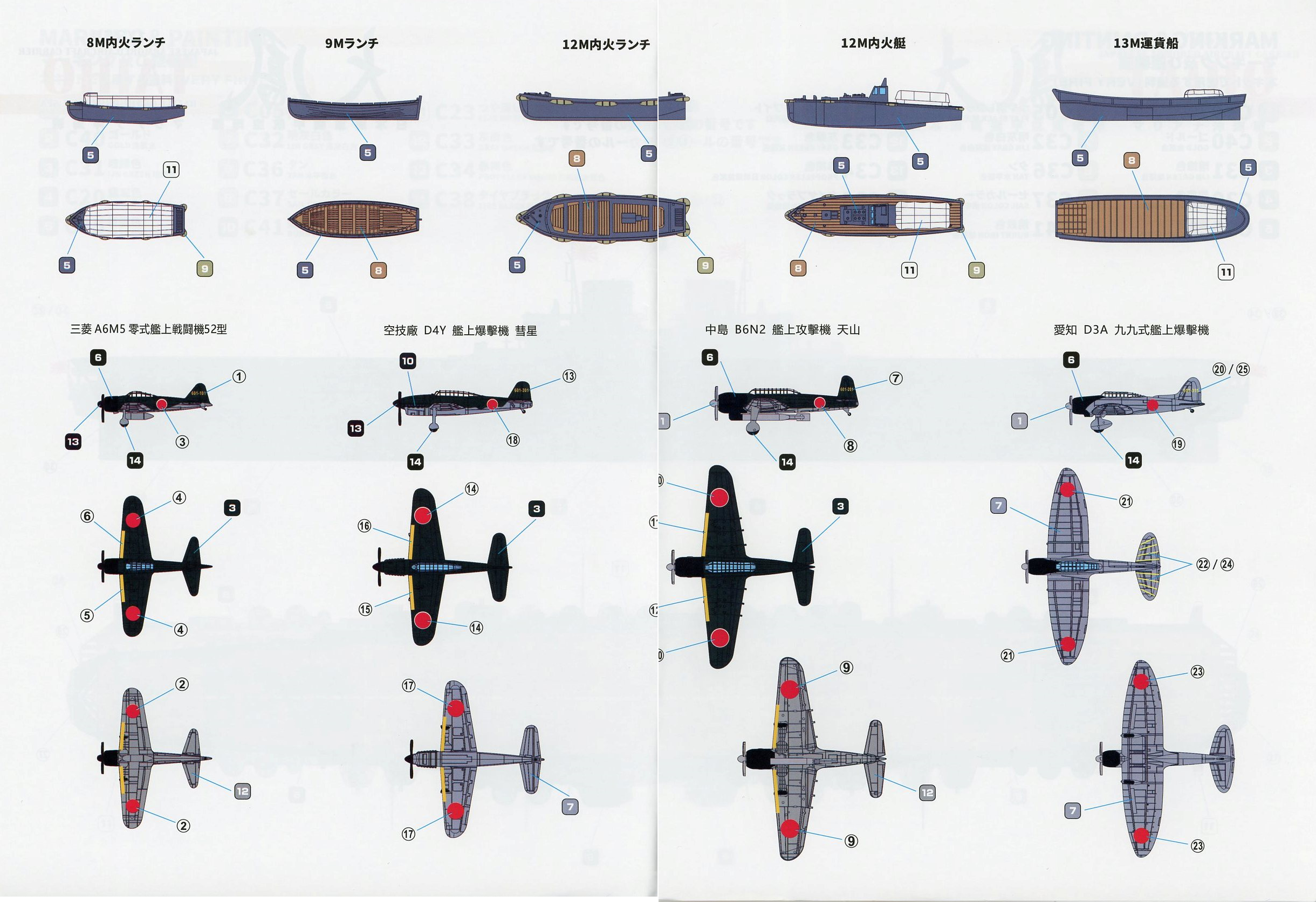
first four of these are the aircraft sprues. The base kit supplies two
each of four types of aircraft.
(In order to gain a full air group, Very Fires sells a separate accessory set of aircraft, known as the Detail Up Parts Set C. In addition to a mix of forty-seven aircraft, it also comes with enough photoetch, including canopy frames, to handle both these aircraft plus the eight that come with the kit. Aircraft decals for all are also included.) Regarding the aircraft: the moldings are excellent, with subtle, engraved panel lines, defined exhaust stacks, raised and well-defined canopy frames, and, excepting the “Vals”, open wells for the landing gear show ribbing from the underside of the wing. What a superb touch, even if these are unlikely to be seen when placed on the flight deck. Even better is that every type has an open cockpit, good for detailing interiors. (The Part C comes with resin semi-interiors for the aircraft.) These are superbly done aircraft. |
||||||||||
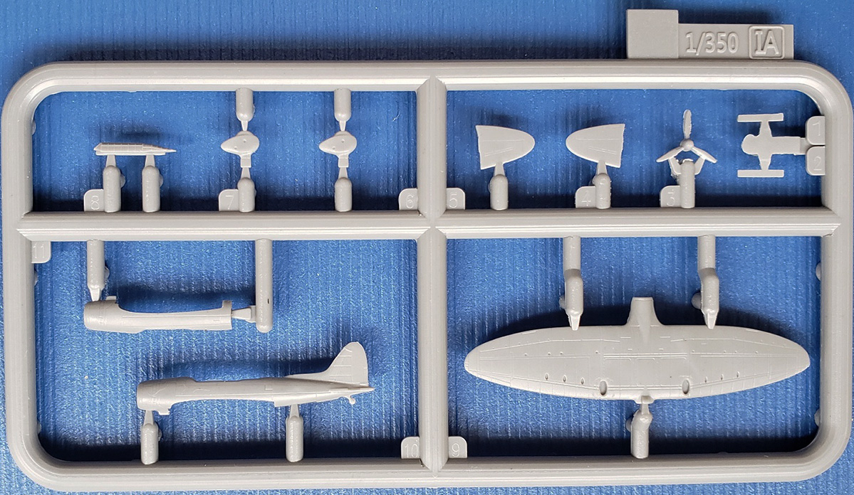
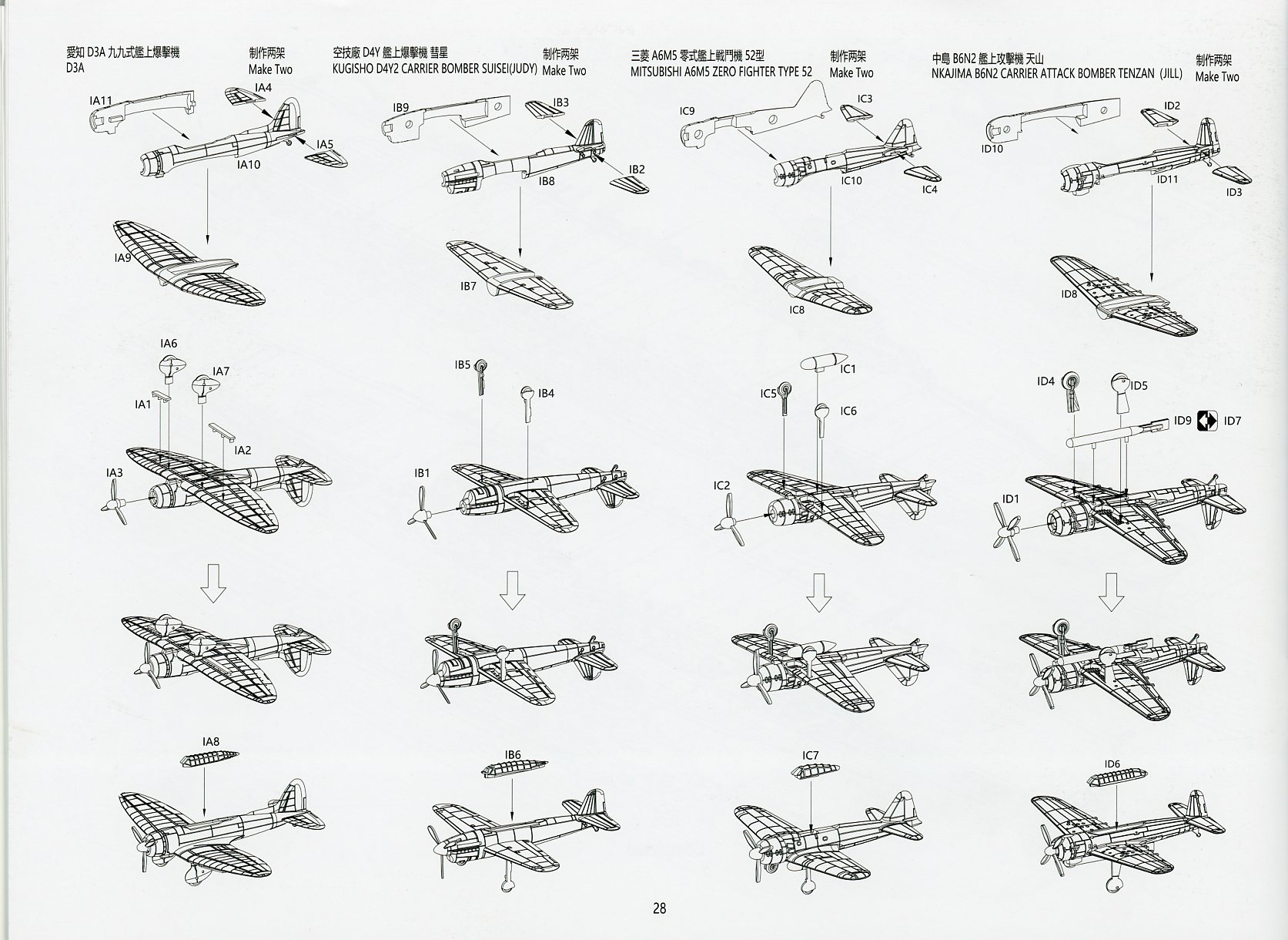
| Sprue IA | ||||||||||
| Two Aichi D3A2 Model 22 (Allied code
name “Val”) dive bombers are provided for. Each consists of a two-part
fuselage, a one-part main wing, tailplanes, propeller, fixed landing gear,
dive brakes, and separate canopy. No external ordnance is provided for.
At this stage of the war, the “Val” had been superseded by the “Judy” in the dive bomber role. A handful of “Vals” were carried aboard Taiho to perform in the antisubmarine warfare (ASW) role. Very Fire has correctly distinguished the later war D3A2 model from the better known D3A1 model by molding a properly lengthened canopy and providing a spinner for the propeller. |
||||||||||
|
||||||||||
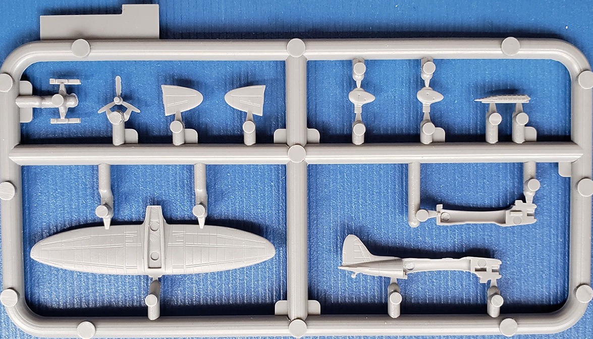
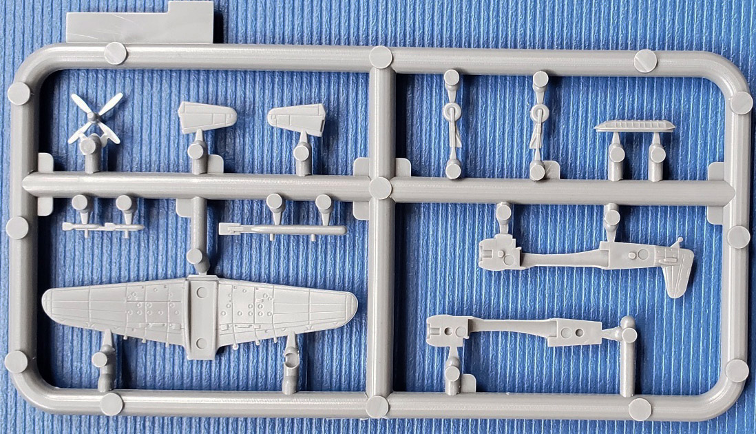
| Sprue IB | ||||||||||
| These sprues hold the parts for two Yokosuka D4Y1 Model 11 Suisei (“Comet”, Allied code name “Judy”) dive bombers. Each consists of a two-part fuselage, a one-part main wing, tailplanes, propeller, landing gear and separate canopy. There is no external ordnance, as these were carried within the internal bomb bay. | ||||||||||
|
||||||||||
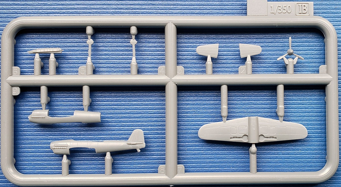
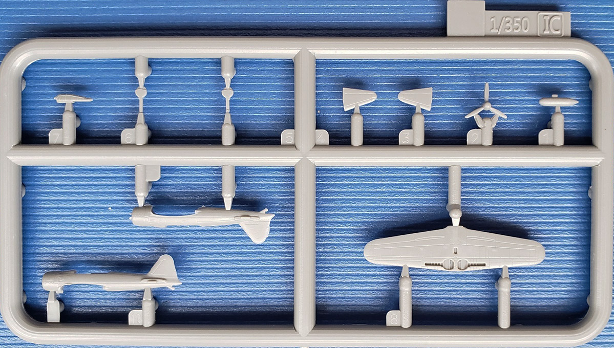
| Sprue IC | ||||||||||
| Contained are two Mitsubishi A6M5 Model 52 (“Reisen”, Allied code name “Zeke” or “Zero”) fighters. Each consists of a two-part fuselage, a one-part main wing, tailplanes, propeller, landing gear and separate canopy. There is an externally carried drop tank as well. | ||||||||||
|
||||||||||
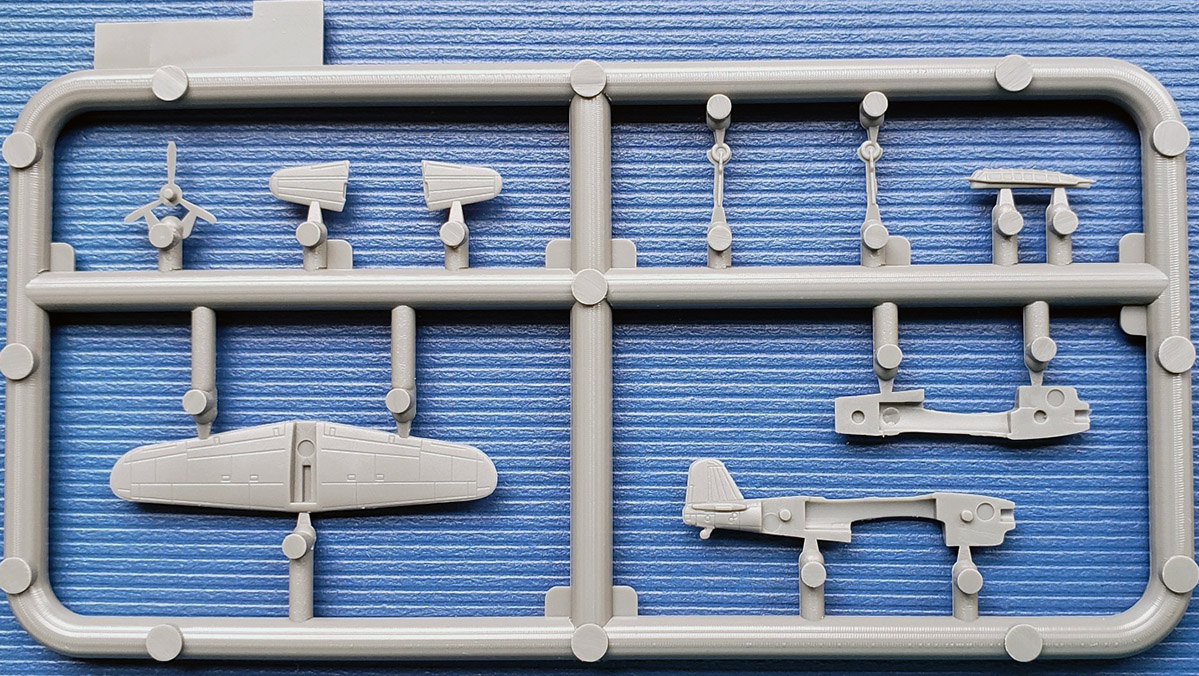
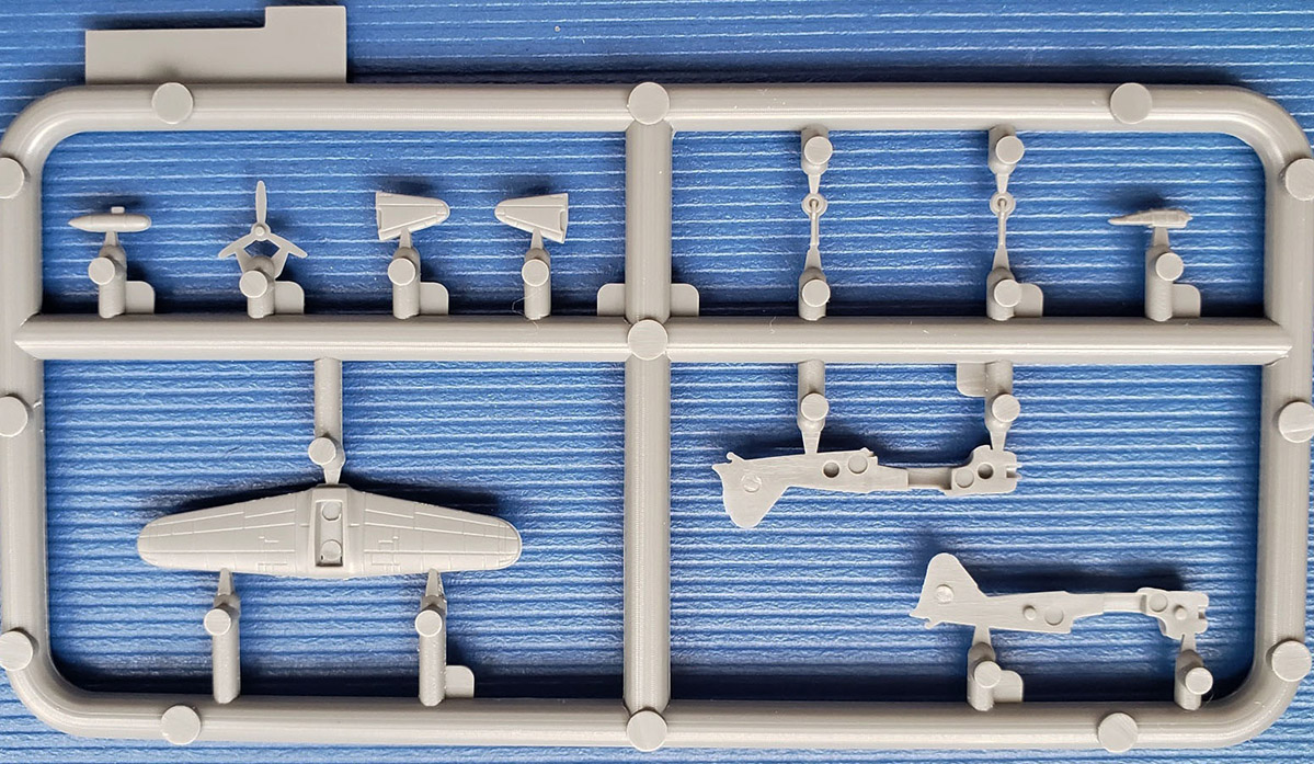
| Sprue ID | ||||||||||
| These are the two Nakajima B6N2 Model 12 Tenzan (“Heavenly Mountain”, Allied code name “Jill”) torpedo bomber. Like-wise to the other aircraft, each consists of a two-part fuselage, a one-part main wing, tailplanes, propeller, landing gear and separate canopy. Also included are a Type 91 aerial torpedo with special fins and an alternative ordinance load of two 250kg Type 98 No. 25 land bombs. Both types of ordnance are carried externally. | ||||||||||
|
||||||||||
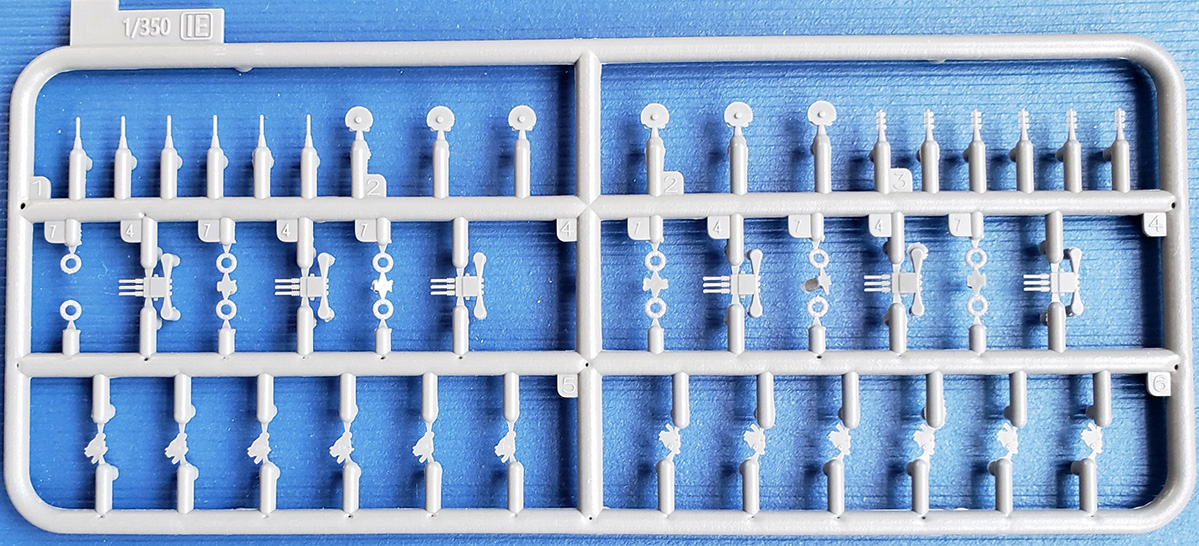
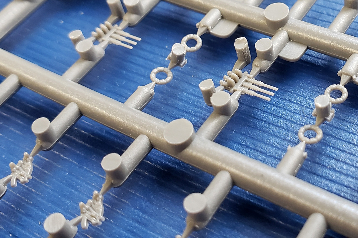
| Sprue IE x 3 | ||||||||||
| Dedicated to the triple 25mm AA mounts,
each sprue carries the components for six mounts, plus some life rings.
Each individual mount has 6 pieces: a base, right and left carriage halves,
two connectors, and a one-piece molding of the three barrels, detailed
with ammo feeds, recoil tubes, and muzzles. No splinter shields are provided,
which is surprising, particularly since those are included with the Super
Set A photo etch versions of the mount.
The entire mount is perhaps a little more detailed than styrene versions from Fujimi, Hasegawa and Tamiya, but the mount assembly is a bit complicated. Personally, I feel that a styrene alternative like the Fine Molds 1/350 version offers better details and scaling with fewer pieces. The same is true of several 3D printed versions out there. Of course, if one really wants fine details and doesn’t mind complicated assemblies, then one can turn to the Super Set A, which does offer a multi-part photo etch version along with turned brass barrels. As do several other aftermarket suppliers. |
||||||||||
|
||||||||||
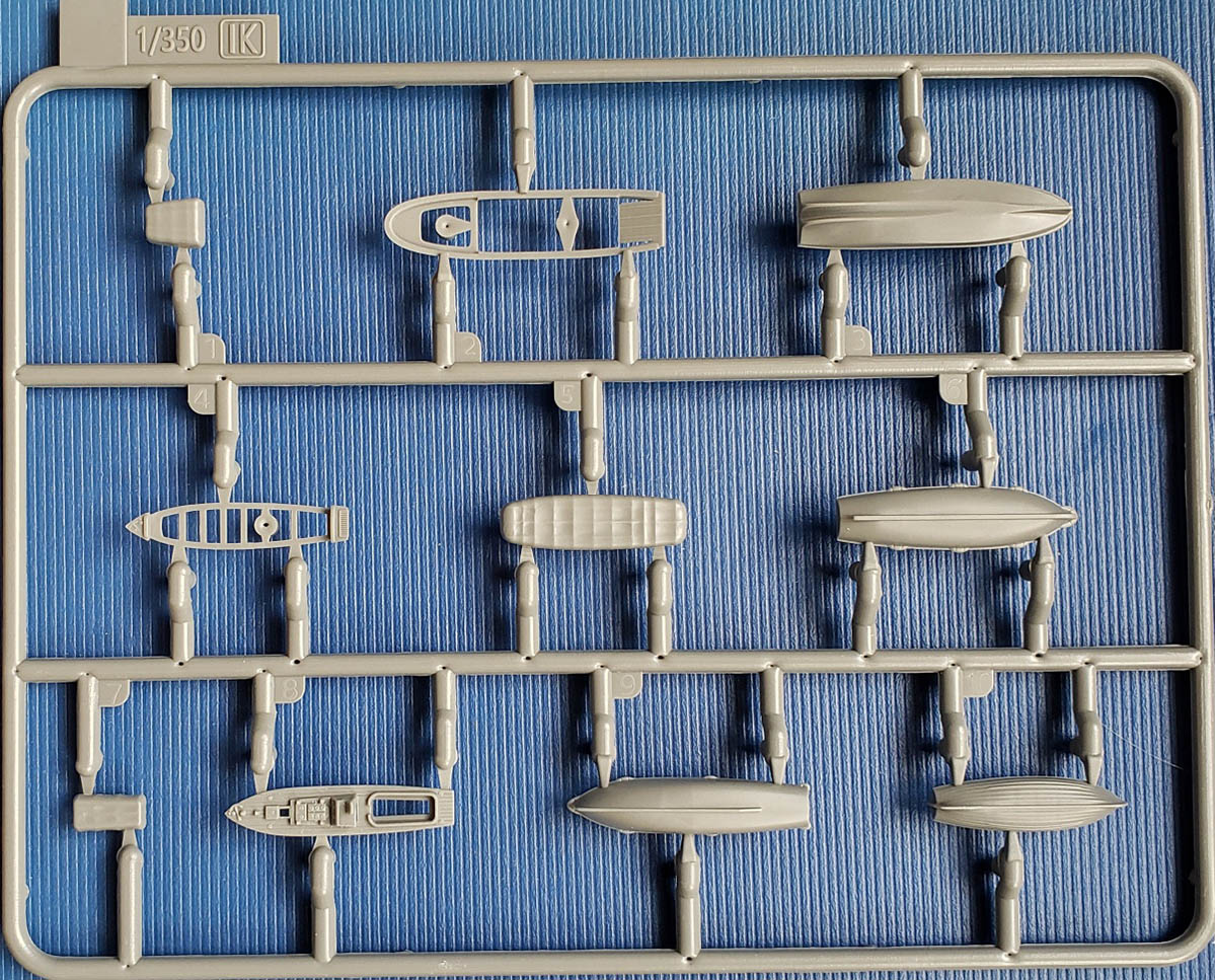
| Sprue IK x 3 | ||||||||||
| The first of two different boat sprues
this carries the top and bottom of a 13m Daihatsu, a 9m cutter, the parts
to a 11m motor launch and the parts to a 11m motor boat. All are sharply
molded. The cutter and motor launch have planked outer decks and flooring.
Both 12m boats have small bumpers at the gunwales.
Not all of these boats are used on this kit. |
||||||||||
|
||||||||||
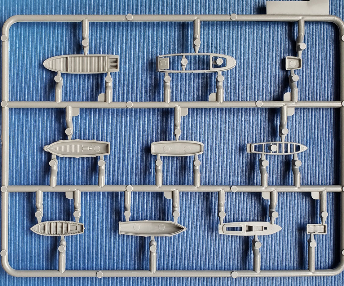
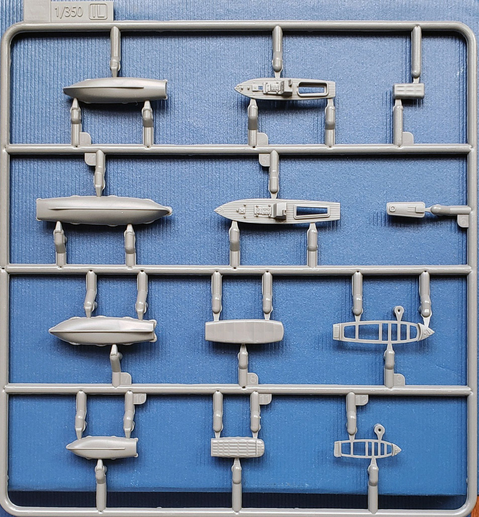
| Sprue IL x 3 | ||||||||||
| The second of the two ship’s boat sprues, this carries the components to a 15m Admiral’s (motor) barge, a 12m motor launch, a 12m motor boat, and a 7.5m motor boat (for destroyers). Detailing is the same as on Sprue IK and, likewise, not all boats are used for this kit. | ||||||||||
|
||||||||||
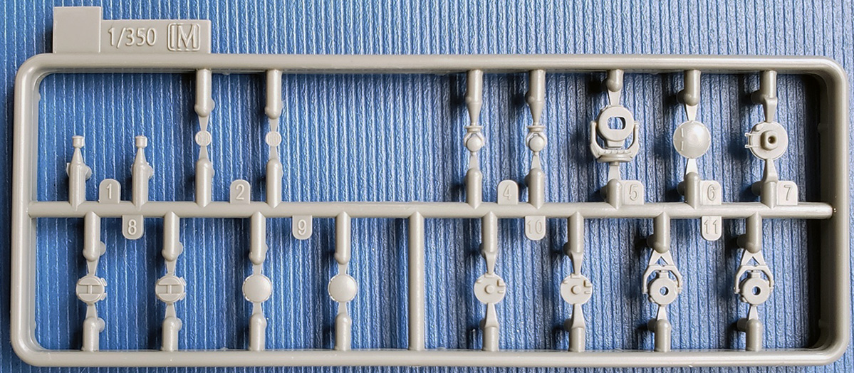
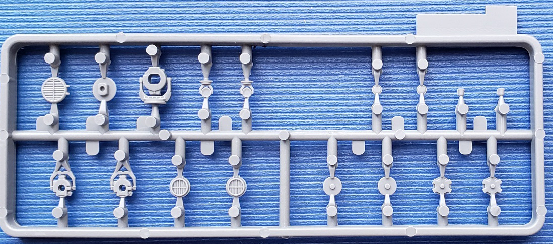
| Sprue IM x 2 | ||||||||||
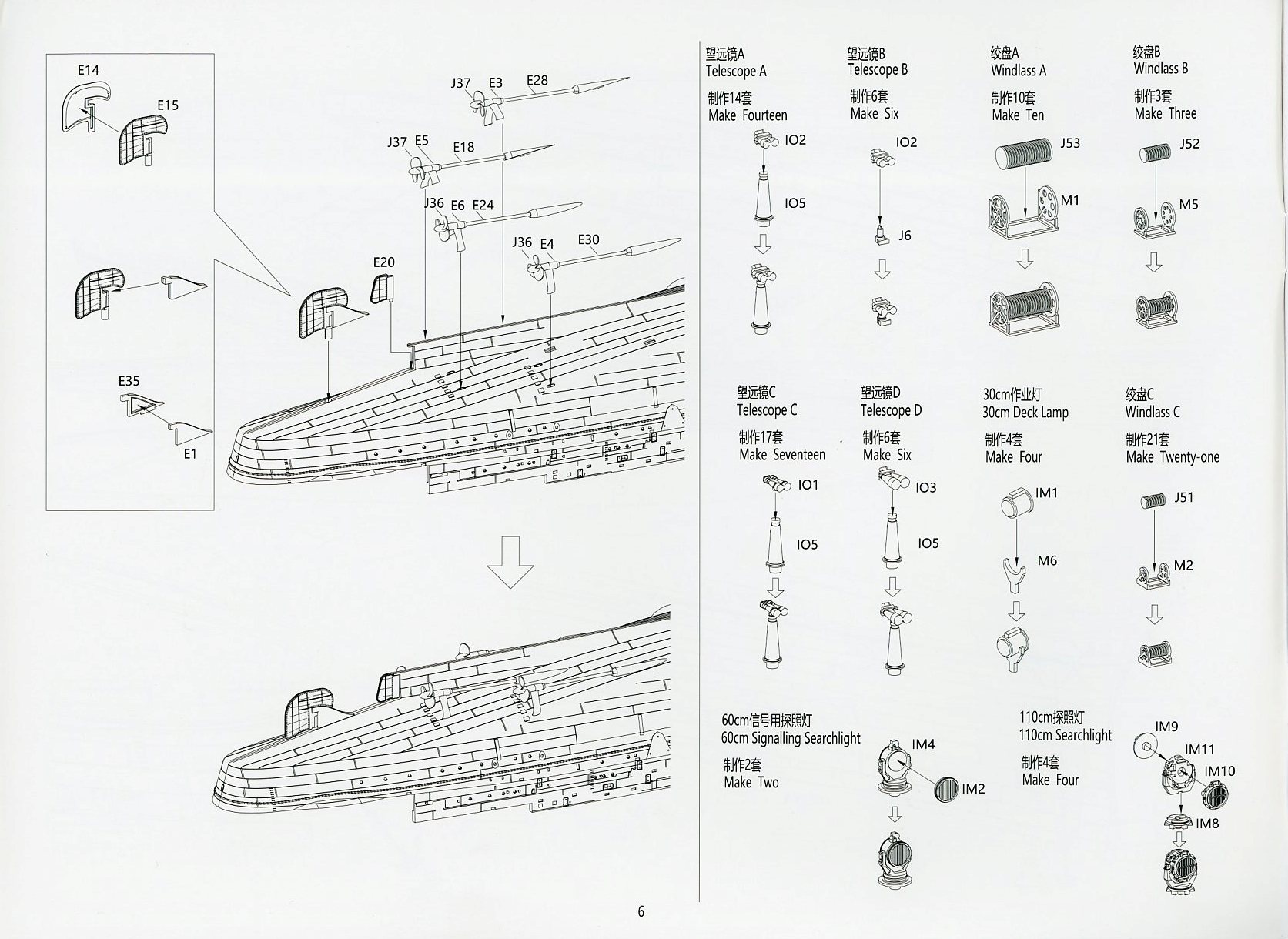
| This is the “searchlight” sprue. Included
are the housings for two 30cm searchlights, two 60cm searchlights and separate
lens covers, the four components for each of two 110cm searchlights, and
what appears to the components of a 150cm searchlight.
The 150cm search light is specific to the Yamato class BBs, and not used here. All of the searchlight lens are grey, and not clear. |
||||||||||
|
||||||||||
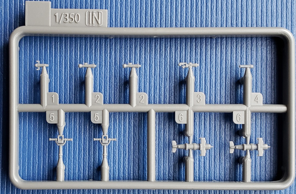
| Sprue IN x 2 | ||||||||||
| This sprue holds two compass binnacles,
some other compass bridge deck equipment, two 1.5m navigation rangefinders,
and two paravanes. All are sharply molded. The navigation rangefinders
and paravanes are clearly marked for use on the instructions.
The other equipment is not indicated for use because the interior of the bridge is blocked off by solid styrene windows. They could be used if the styrene bridge windows are replaced by photoetch window frames. Those are available from the Super Set A, or other aftermarket sources. |
||||||||||
|
||||||||||
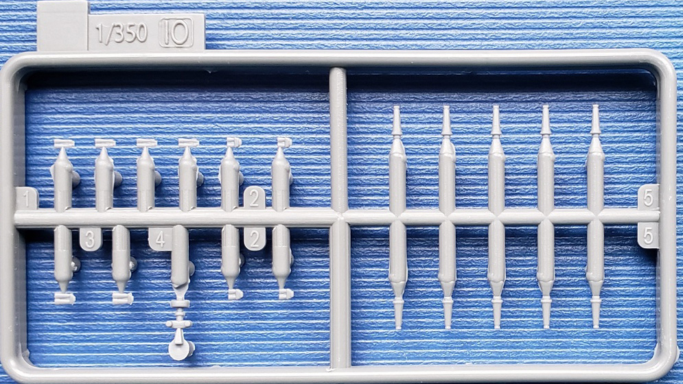
| Sprue IO x 6 | ||||||||||
| Consists of four types of high-powered search binoculars (predominantly 12cm types), support columns for the same, and a Type 94 searchlight controller. | ||||||||||
|
||||||||||
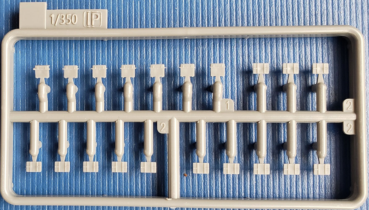
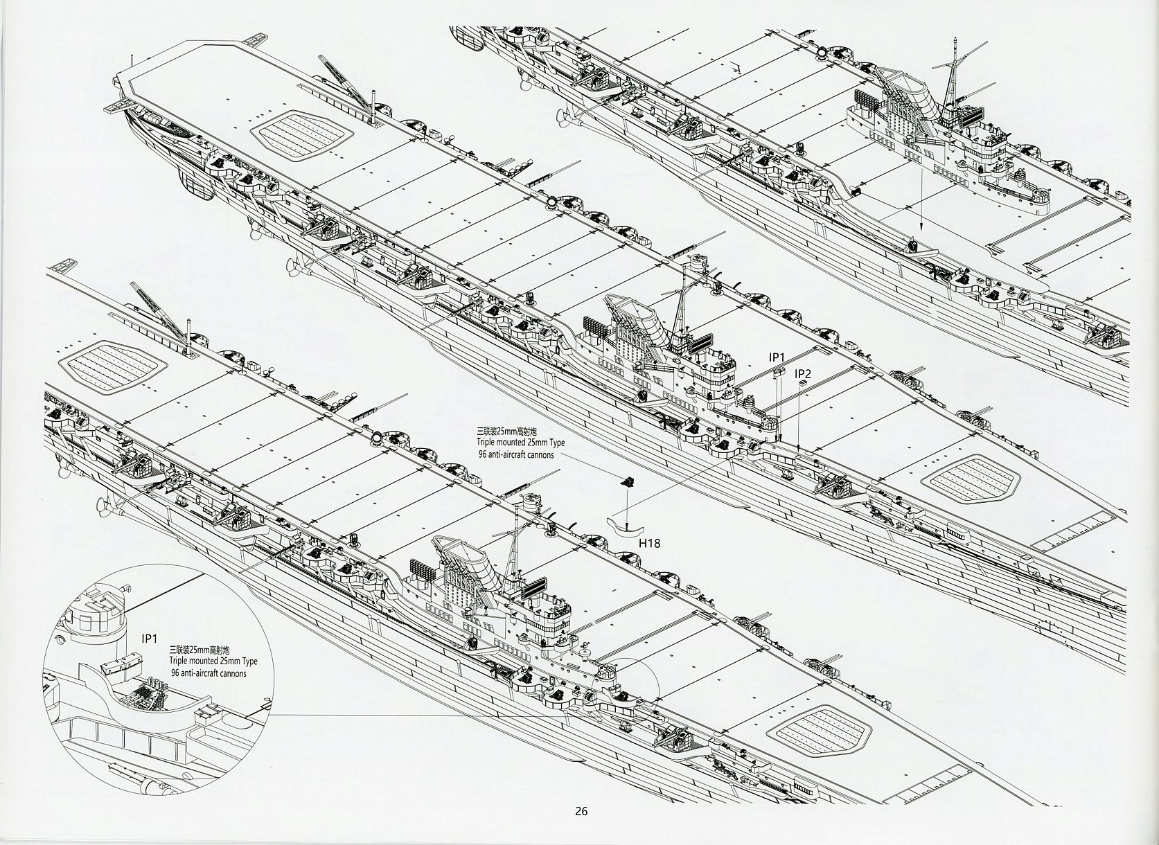
| Sprue IP x 5 | ||||||||||
| Devoted strictly to 25mm ammo boxes, of which there are two types. All have clearly molded hinges. | ||||||||||
|
||||||||||
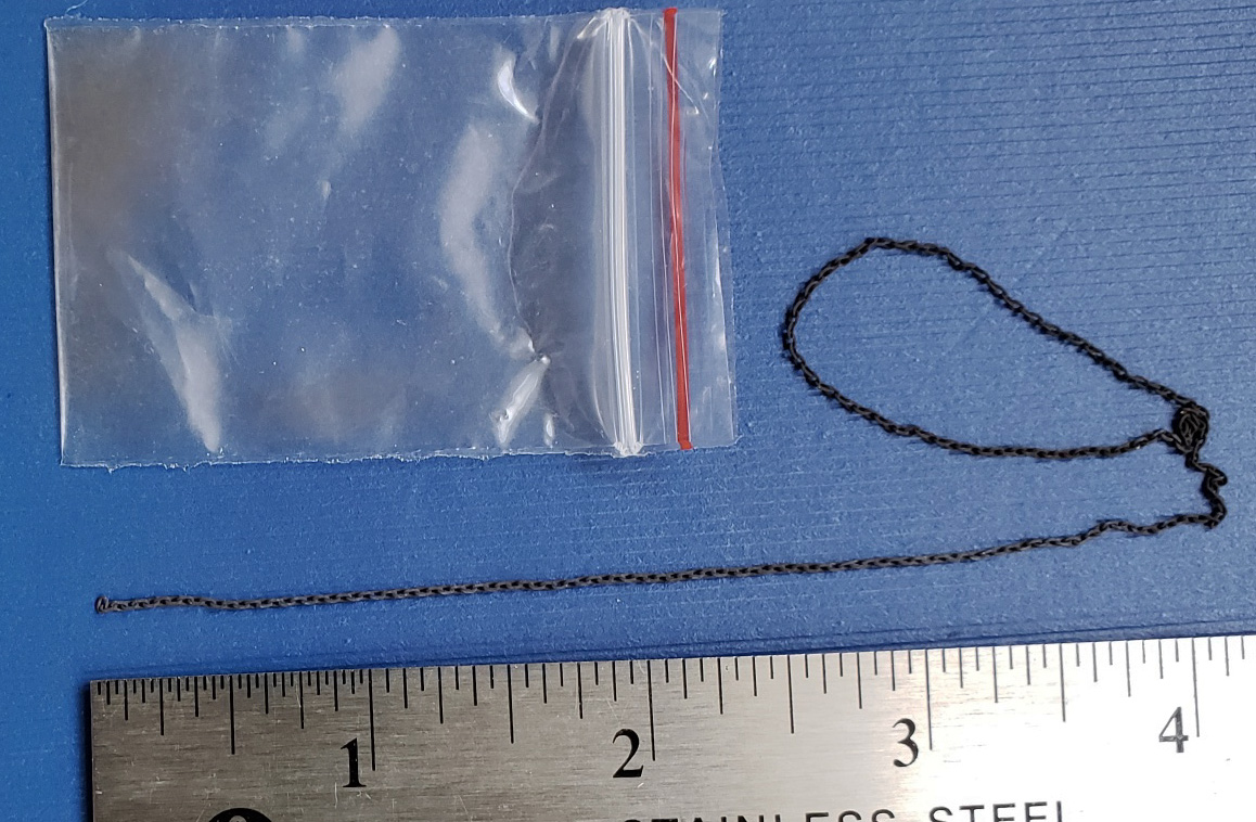
| Chain | ||||||||||
| The kit contains approximately nine inches of metal linked chain to be used for the anchor chains. These are finished in a matte dark grey-black and measures approximately 25 links to the inch. | ||||||||||
|
||||||||||
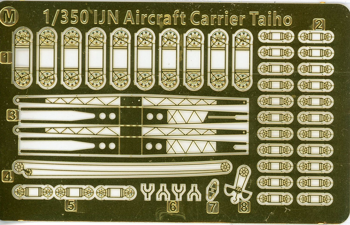
| Sprue M (Brass) | ||||||||||
| This kit does come with a small brass fret of relief etched photoetch. Included are three types of hawser reels and the components to the aircraft handling crane. A particularly nice touch are the crane pulleys with cables. The reels and pulleys are relief etched. | ||||||||||
|
||||||||||
| Decals | ||||||||||
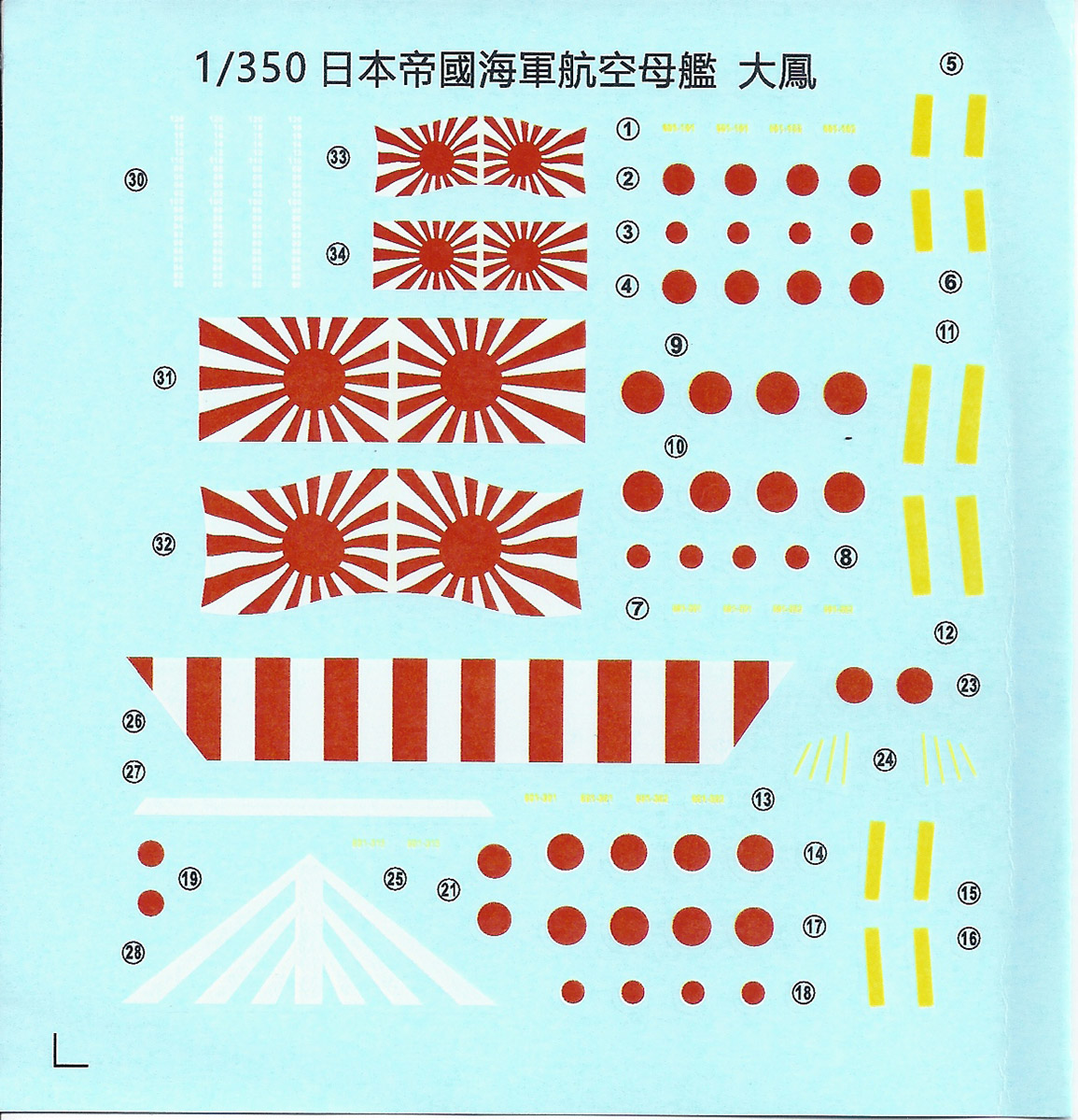
| The kit comes with a small decal sheet.
Aside from the red and white warning strip for the aft end of the flight
deck, Plimsoll markings and a wind bearing fan indicator for the bow of
the flight deck, the decals are mostly IJN flags and aircraft markings.
Due to the lack of clear documentation, the wind bearing fan lines meant
for the bow must be considered speculative. Unfortunately, there are no
deck striping decals; the modeler will have to paint these on using their
own marked off flight deck or used the masking template included with Very
Fire’s Detail Up Set B accessory set.
There are no registration issues and the decal edges are sharply delineated. |
||||||||||
|
||||||||||
| Instructions | ||||||||||
| The instructions are presented in
a very nicely printed, 28-page booklet printed in black and white. There’s
a reprint of the cover art and a short history of Taiho in English, followed
by a 2-page graphic illustration of the sprue layout. The rest of the booklet
depicts the build in step by step, exploded, three-point perspective views
of assembly. Many parts and assemblies are also subtitled in English. Aircraft
assembly is covered on the last page of the booklet.
The booklet is sizable, so the instructions are easy to see. They are also very straightforward, but the high number of accessory frets starting with the letter “I” can seem a little overwhelming at times. As there are a great many subassemblies, it is important to double-check the instructions. |
||||||||||
|
||||||||||
|
||||||||||
| Final Impressions | ||||||||||
The allure of Taiho is not hard to
discern. An innovative and aesthetically pleasing design, heavily armored
against bombs, torpedoes and shellfire, and the what-ifs of a short history,
have made her an undeniable favorite of mine. Not to mention many other
armchair admirals, IJN fans, and modelers.

I never expected to see this ship kitted in this scale in my lifetime. Nor done as well as it is. In many ways, it is reminiscent of Hasegawa’s excellent 1/350 Junyo and Hiyo aircraft carrier kits in terms of detail and execution, though I feel that Very Fire has exceeded those qualities with this kit. Having dreamed of this kit for so long, I wanted it to be perfect. Of course, no kit ever is. I make no apologies for my nitpicks; I’m passionate about my hobby and happen to be highly focused on details of this sort for this particular kit. That said, most of the issues that I‘ve pointed out are truly nitpicks, and are easily correctable if one is so inclined. Like-wise, they can also be ignored without any significant impact on the final appearance of the model. However, as fine a kit as this is, I am troubled by what appears to be the conscious omissions of some details on the molded kit while including photo etch versions of these same details with relatively expensive accessory sets that are sold separately. Though this is the first Very Fire kit I have reviewed, I am told that this same circumstance is common to some of their other releases as well. I think it’s a questionable marketing practice. Not every modeler wants to add photo-etch, or can afford the additional set(s). They shouldn’t be penalized by these omissions, particularly when provision of all relevant details to a kit is pretty much standard for the hobby. That one unfortunate aspect aside, I think it’s a great kit. Fit remains to be seen, though Very Fire’s reputation in this regard is very good. I’ll also mention that most of the sprues with a two-letter designation starting with the letter “I” are general sprues for IJN warships. That signals more potential Imperial Japanese Navy warships in the Very Fire pipeline. To that end, they have announced a late war Aoba heavy cruiser as in development. HIGHLY recommended (with said qualifier) A heartfelt thanks to HobbyLink Japan for the review kit. The manufacturer’s suggested retail price appears to be approximately US$190. |
||||||||||