Building the Heavy Cruiser
Tone
Building Minekaze's 1/350 resin kit
by Martin J Quinn

Operational History
Laid down in 1934 as the next step in Japanese Cruiser
design, the Tone and Chikuma were originally conceived as
large light cruisers, with the same armament (6.1 inch guns) as were mounted
on the Mogami-class. Early on in construction, Japan
abrogated the London Naval treaty and the Tone-class was completed
as heavy cruisers with 8 inch guns. Unlike the Mogami, which
had her aircraft deck added after the damage she suffered at the Battle
of Midway, the Tones were designed to acts as scouts and to carry
a large complement of floatplanes. This gave them their distinctive
look with all four turrets forward of the superstructure and a large aircraft
deck aft.
Tone served alongside Chikuma as part
of the Cruiser Division 8 for most of her career. As
the war in the Pacific began, CruDiv 8 participated in the Pearl Harbor
raid and the capture of Wake Island. They also participated
in the raid on Darwin, Australia and the sweep of the Java area in late
February, 1942, when Tone helped sink the American destroyer USS
Edsall
(DD-219). Again escorting the carriers, CruDiv 8 was
part of the Japanese March 1942 raid into the Indian Ocean. It was
Tone's scout plane that found the British cruisers HMS Dorsetshire
and Cornwall, which led to their destruction by Japanese carrier
aircraft. After the unsuccessful pursuit of Task Force
16 in the wake of the Doolittle Raid, Tone and Chikuma underwent
a short refit at Maizuru.
Post-refit, CruDiv8 was part of Operation MI and the
Battle of Midway, where Tone's scout planes played a crucial role
in the battle. A float plane that launched late found
the American ships, but either didn't recognize or neglected to report
that one of those ships was a carrier. In a battle that
is described in great detail elsewhere, the Japanese ended up losing four
of their frontline carriers as well as their precious aircrews. As
the Japanese fleet retired from the Midway debacle, CruDiv 8 was dispatched
to support the Aleutian Island operations, in anticipation of an American
counter-attack that never came.
Tone next saw action as part of the Japanese
response to the American invasion of Guadalcanal. She and Chikuma
escorted the carrier Ryujo during the Battle of the Eastern Solomons
on August 24, 1942, escaping serious damage while Ryujo was sunk.
In mid-October, Tone and a destroyer were sent to search for the
American fleet, which did not appear, north of the Santa Cruz Islands.
Later that month, on October 26th, her floatplanes spotted the American
carrier Hornet during the Battle of Santa Cruz, which resulted
in the Hornet being sunk.
After conducting support missions and patrols in the
Solomons, Tone returned to Japan for a refit in February, 1943.
During this time, her AA armament was upgraded slightly and radar was installed.
Tone was part of the force assembled for the abortive mission to
repulse the American attack on the Aleutian Islands. After
ferrying troops and supplies to Rabaul, she was based out of Truk with
other major units of the Imperial Navy. From here the
Japanese sailed to respond - in vain - to American carrier raids on Makin
in September and the Marshall Islands in October.
After a refit at Kure in December, 1943 - during which
Tone's
AA fit was increased again - CruDiv 8 was disbanded.
Tone and Chikuma
were assigned to CruDiv 7 with the Kumano and Suzuya in January
1944. In March, Tone participated in the infamous Indian Ocean
raid, where she sunk the British freighter SS Behar and executed
72 prisoners on board in retaliation for sending a wireless raider report.
Tone was present for the Battle of the Philippine
Sea, then returned to Japan for further upgrades to her AA and radar suites.
Returning to the fleet, she moved between the Philippines and Singapore
before participating in the Battle of Leyte Gulf, where she was damaged
by US Navy carrier aircraft. After escaping further harm, Tone
made her way back to Japan for repairs and further AA and radar upgrade
in November. Due to the loss of Chikuma and
Suzuya
at Leyte Gulf, CruDiv 7 was disbanded and Tone was assigned to CruDiv
5 with the Kumano - who was soon sunk herself.
Tone spent the rest of the war moored near the
Kure naval base. With fuel at a premium and the American fleet running
amok in the Pacific, there was no place for her to go. Damaged
by a carrier raid in March, 1945, Tone was finally sunk on July
24, 1945 by US carrier aircraft. Her hulk was raised and scrapped
postwar.
Sources:
Cruisers of World War Two, MJ Whitley
Japanese Cruisers of the Pacific War, Lacroix
and Wells
Tabular Record of Movement (TROM),
Combined
Fleet.com
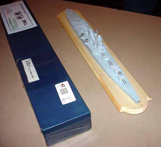
Building the Tone
I've done several build up reviews for ModelWarships, but this build was
an unusual one for me. Not because of the model itself, but because
I inherited this model after it had already been started by someone else.
Back when Minekaze released this kit, Tim Dike had received a sample for
the subject for both an in-box and build-up review. The model
was then given to someone to do a build up review. Unfortunately,
about 1/3 of the way through the build-up review project, the modeler who
had started the Tone was unable to continue due to personal issues.
After some discussion, I was asked if I wanted to pick up the project and
continue, partially because I had access to the model and the modeler,
and also because I could start the project pretty quickly.
Since I have a closet full of models to build, I would have normally said
no. But, since this was such an unusual subject in 1/350, I
agreed to take it on. So, once I had finished building and writing
some other pending reviews, I picked up the model and took stock of what
I had.
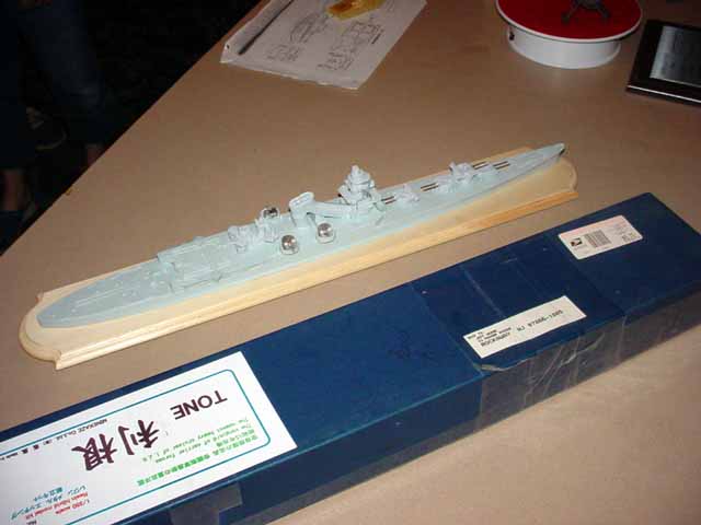
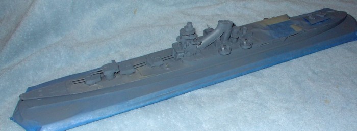
I received a model that was about 30-35% done - though at first glance
it looked like it was farther along. The superstructure, smoke stack
and turrets had all been attached, and the deck and vertical surfaces all
painted with acrylic paint (to my dismay, since I normally paint with enamels).
None of the photo-etch parts or white metal parts had been painted, nor
had the remaining resin parts. Unfortunately, the person I
had gotten the kit from didn't remember what brand or color he had done
his painting with, so I was going to have to repaint everything he had
done if I wanted all the parts to match (which seemed sort of important
to me).
Before I went any further, I did some research. I picked
up the Gakken book on the Tone (which I was personally disappointed
in) and read over the chapter on the Tone and Chikuma in Lacroix
and Wells "Japanese Cruisers of the Pacific War". I also borrowed
a set of 1/200 plans for the Tone to use as a further reference and printed
some pictures of the built up kit from the web. Finally,
I turned to Ed Low's superb Japanese
Warships in 3-D website for details on the bridge and other structures.
Some further research found that the Minekaze kit represents the Tone
prior to December, 1941. Other than receiving Jakes to replace
her Type 95 Alf floatplanes, Tone was virtually unchanged from her
launch, until 1943, when she received her first major alterations while
undergoing refit. Having always been fascinated
with the Battle of Midway, I decided to model Tone as she appeared
on the morning of June 4, 1942, when her difficulty in launching one of
her scouts had disastrous consequences for the Kido Butai.
Tone
had been repainted during a short yard period just before the Midway operation
at the Maizuru Naval Arsenal, so she would be painted in Maizuru grey.
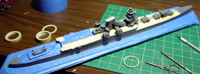
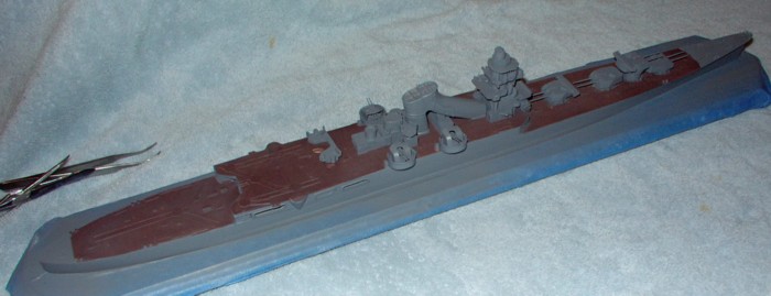
Once I had decided on the paint color, I took the remaining parts out
of the box, washed everything in warm soapy water, then primed them.
Then, I masked the deck and repainted the hull assembly with Model
Master Acrylics Maizuru Grey. I then painted all the primed
parts the same color. Once I unmasked the deck, I examined
how much touch up painting there was to do, and prepared to finish my research
and start construction.
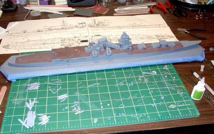
While continuing to do some research, I got down to building by reviewing
the instructions. I'll say this right here because it will
be a recurring theme in this review: the weakest part of the kit
are the instructions. Frankly, they are lacking. The
Minekaze kit comes with a plan and profile drawing of the ship, in 1/350
scale. It also comes with a parts list that is several pages long,
two pages that show photo-copies of the parts (and their corresponding
numbers), a sheet detailing the construction of the aircraft and finally
a sheet with some drawing showing details of the bridge and crane.
While the profile and plan view does show were all the parts go, it would
be much better if there was, at minimum, an exploded view drawing.
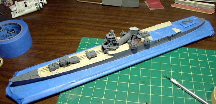
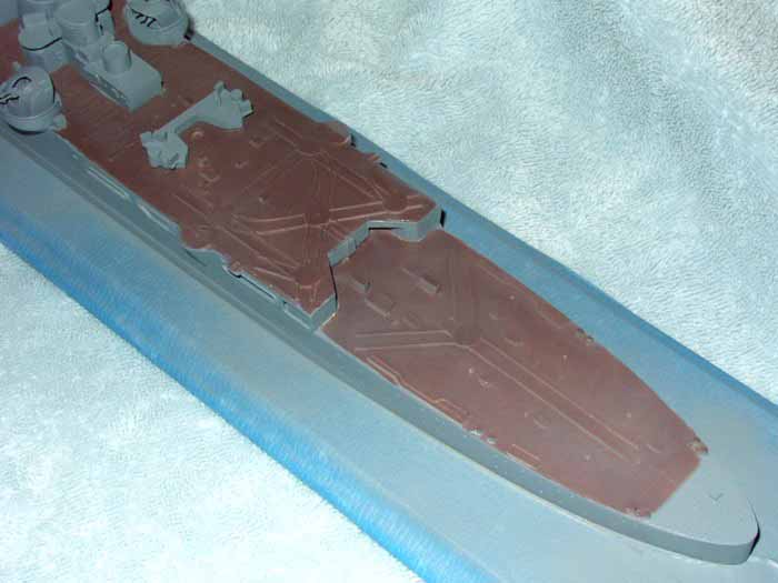
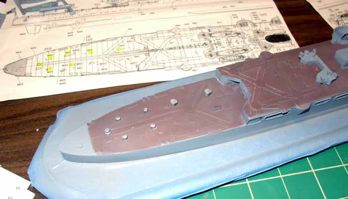
Now ready to start, I laid everything out on my work table and got ready
to begin the actual building. One thing that Minekaze has done -
which is both a blessing and a curse - is to cast almost all of the deck
fittings in white metal. This avoids the unsightly and annoying holes
caused by air bubbles during the casting process. It also means there
are a lot more white metal parts to add! While a bit tedious, I think
it was a good idea - I prefer the tedium that comes from adding white metal
parts than the tedium from filling and sanding malformed parts on the model.
Each deck fitting either has a small outline on the deck to mark it's spot,
or has a small hole for the part. I found I needed to use a
small drill bit to widen and deepen the holes to get the ventilators to
fit properly.
As I said earlier, the directions are lacking, but if you study them carefully,
you should be able to figure them out. Starting at the bow,
I started adding white metal parts, working my way aft. Each
time I added a part, I used a highlighter to mark off that part on the
profile/plan view. This way I knew it was done and wouldn't waste
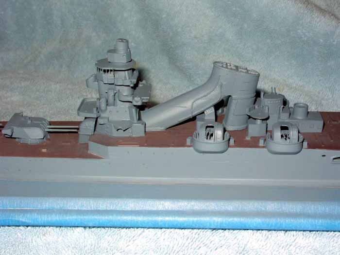
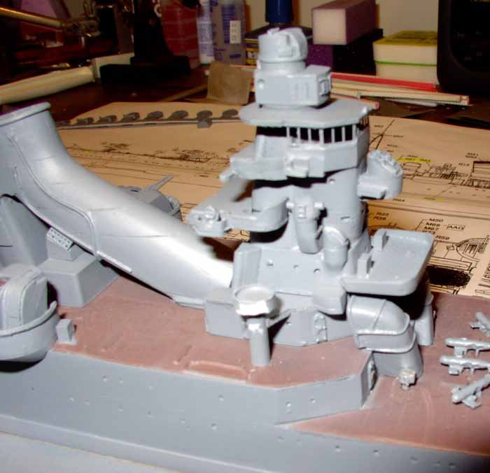
time looking over the same part numbers again and again. After
I had gotten the white metal parts added to the deck, I began adding the
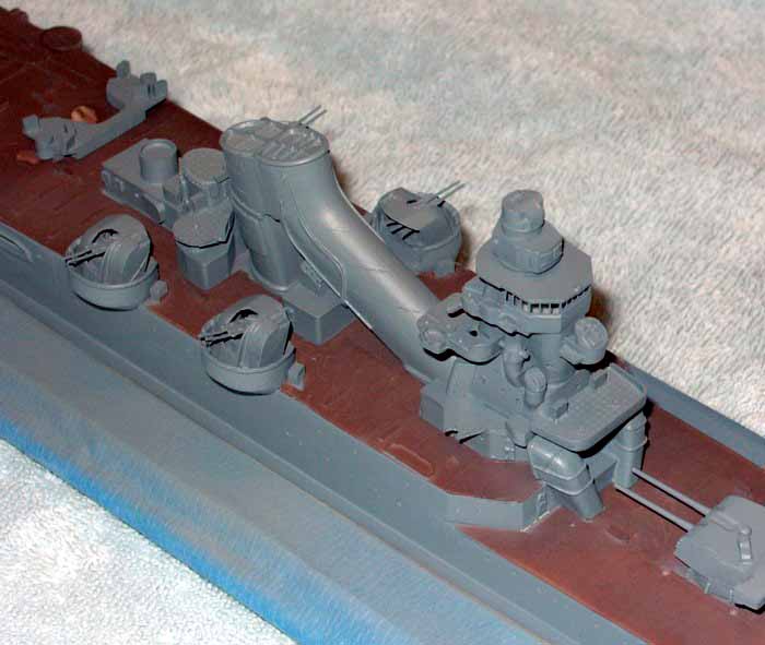
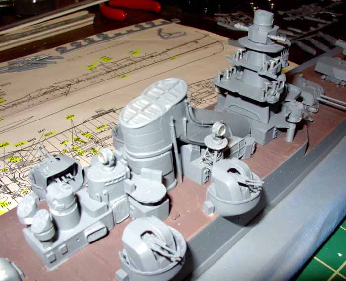
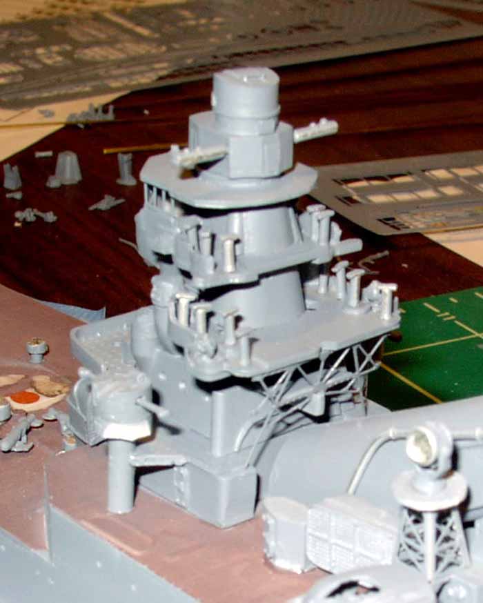
rest of the resin parts to the kit, starting with the superstructure.
My predecessor had build the majority of the bridge, but had left off some
platforms and gun directors. I added these, then worked my way aft,
adding deckhouses, gun directors and vents as I went.
As with the white metal parts, most of the resin parts have a small outline
drawn on the deck to help you place them in the correct place.
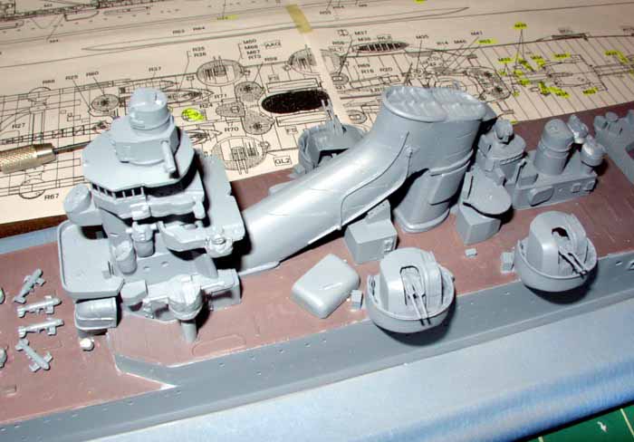
The vents on either side of the funnel also had a small notch cut into
them. The notch matched a molded on pipe on the funnel, so
if the pipe to fit into the notch perfectly, you had the vent on the wrong
side of the ship. I thought this was a good touch to help the
modeler.
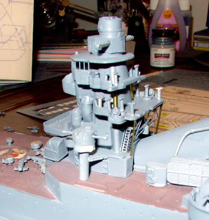
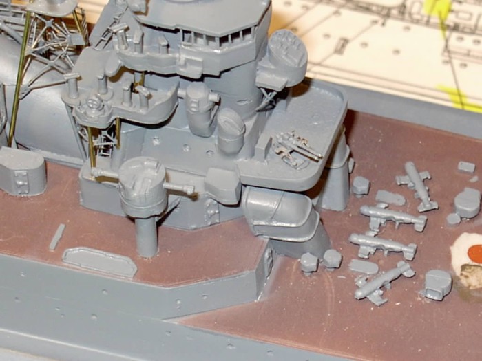
Three of the gun directors had rangefinders. Each rangefinder had
to be cut in two, then inserted into the hole already cast into the sides
of the directors. This took some test fitting to make sure
they rangefinder protruded the same length from each side - the drill came
in handy again to help deepen holes when needed. With the majority
of the resin parts on, I added the searchlight towers on either side of
the funnel. Here the directions really let you down, I needed
to use all the research materials at my disposal to figure out how the
searchlight towers were mounted. In the end, the photo-etch
towers are a millimeter or so short - I ended up having to glue them to
the top of a deckhouse to keep them straight.
I now glued the lookout binoculars (boy, were there are lot of them!) onto
the bridge. I realized the the original builder had omitted
the compass and some lookout positions inside the bridge (which is visible
through the photo-etch windows). Instead of ripping the bridge
apart, I decided to leave them out.
At this point, the majority of the resin parts were on, as were most
of the white metal parts, so I started reviewing the photo-etch sheet,
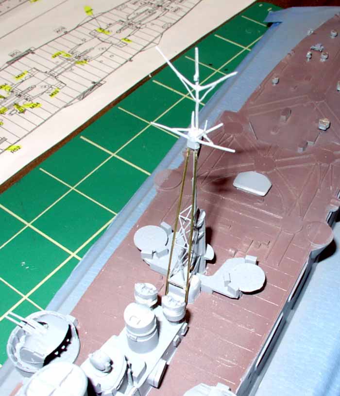
deciding to build the mainmast first. Again - the directions
are of limited help here. Pictures of the real ship, of models
and the 1/200 plans helped me out. The bracing on the
mainmast is a photo-etch part, which I bend into a triangle shape.
I added this to the resin derrick, then a white metal part which represented
the back leg of the mainmast. Using some the brass rod that
was included in the kit, I made the other legs of the tripod. The
deck has holes to locate the mainmast legs in, while the photo-etch has
notches in the corners to locate the brass rod in, which was a huge help
in getting everything to stay together (that along with super glue and
accelerator!) Once the legs and bracing were in, it was time to add
the white metal top of the mainmast. The tricky part was getting
all three legs to be the same height. After a few attempts at getting
all three legs to match, I realized all I was doing was making the mainmast
shorter and shorter. I was finally able to get the brass rod
legs to be the same height, and used a small shim of plastic card on the
bottom of the mainmast top to get that to meet the white metal leg.
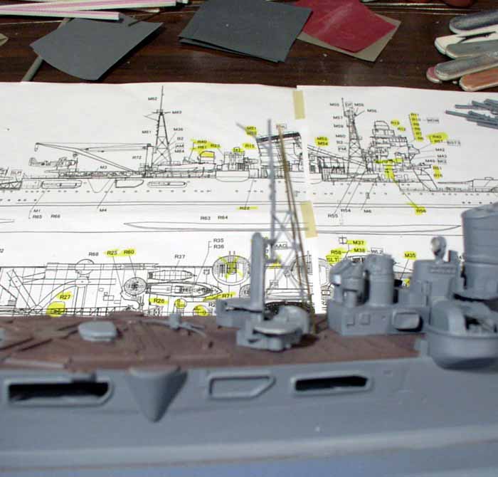
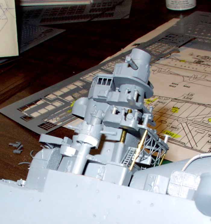
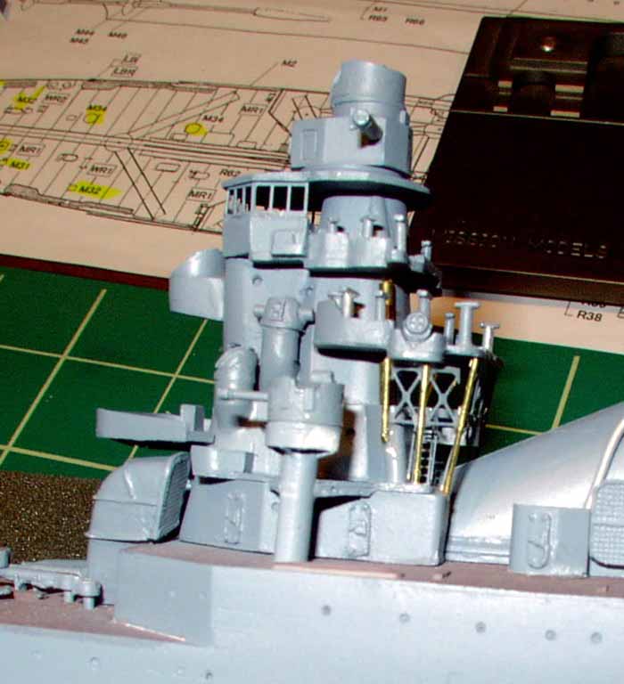
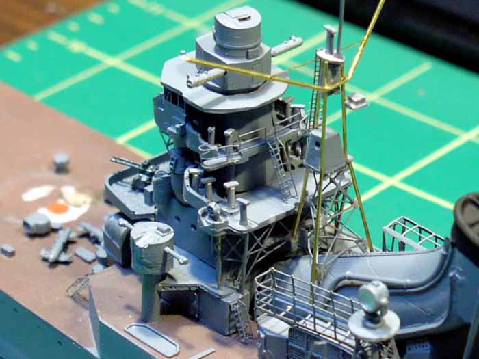
With the mainmast done, I elected to work on the foremast.
Again - the directions were an issue. Before the foremast could
be put on, a several pieces of photo-etch bracing, several sets of photo-etch
stairs and some brass rod supports had to be added to the back of the bridge.
Even though the directions were vague, I was able to figure out the configuration
using the plans and the aforementioned Ed Low's website. I
also realized that a section of the tripod legs that help up the main battery
director were missing. Luckily, I was able to add these without
having to rip the bridge apart.
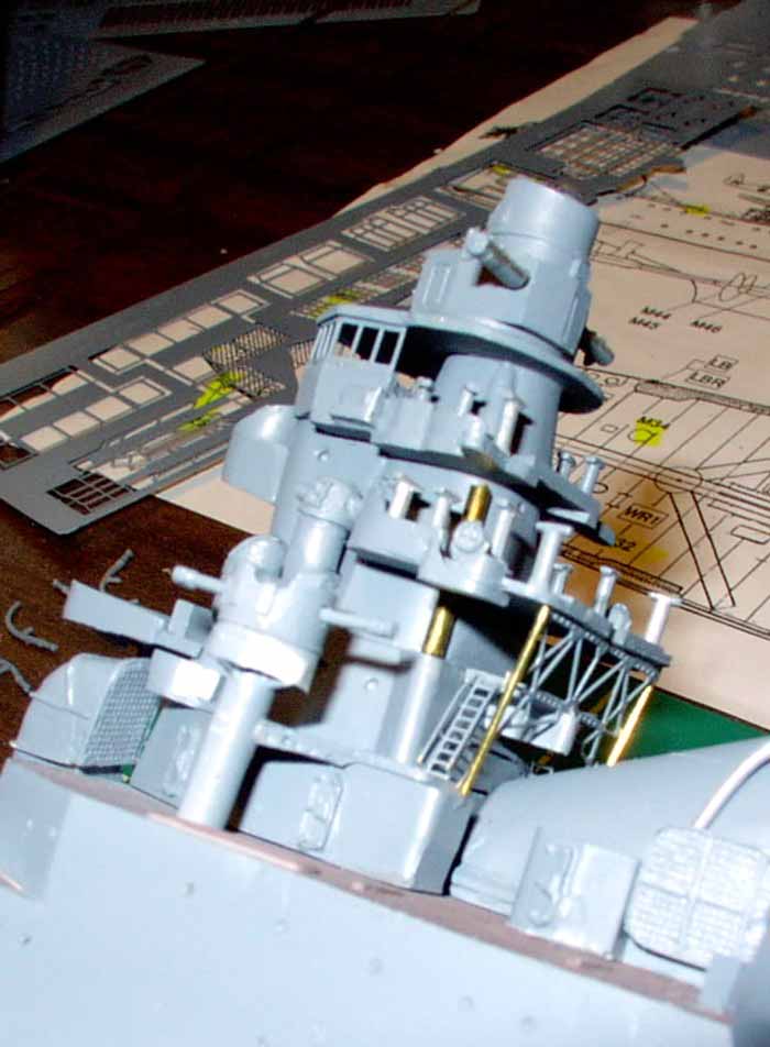
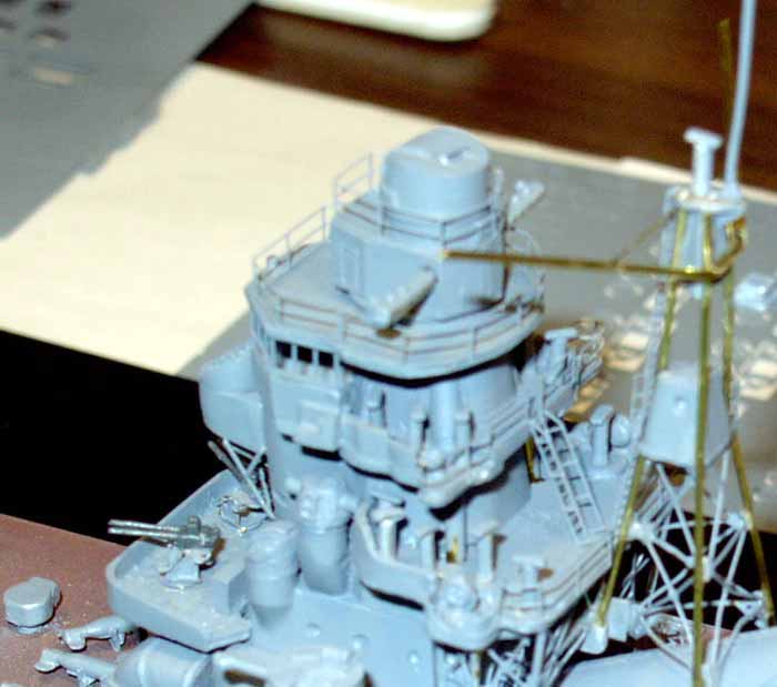
After some careful dry-fitting and testing, the largest piece of the
photo-etching was added to the bridge. I then added the brass
rod to either side of the bracing, then worked on adding the additional
bracing and photo-etching to the port side. Unfortunately,
the brass bracing for the port side doesn't fit properly, if you fit the
brass rod as per the ships plans. I took small piece of scrap
brass, cut it to shape and added it to bridge the gap between the photo-etch
part and the brass support rod.
I ran into similar problems with the foremast. In my opinion,
there should have been a separate drawing for the foremast, but I had to
rely strictly on the profile view. As a result, I had difficulty
with this part of the build. Two times I had the mast about 80% done,
only to find I had to rip it apart and start again. It took
me several attempt to finish it, and in the end, it still wasn't quite
right. I also had to replace the yardarm (which was white metal)
with brass rod, as the white metal part was deformed and too "soft" to
fix.
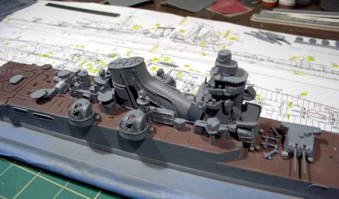
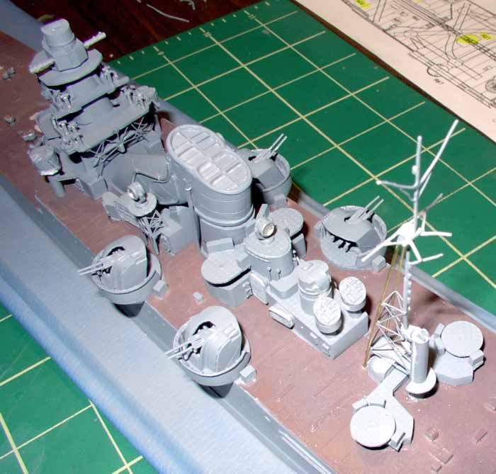
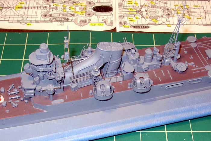
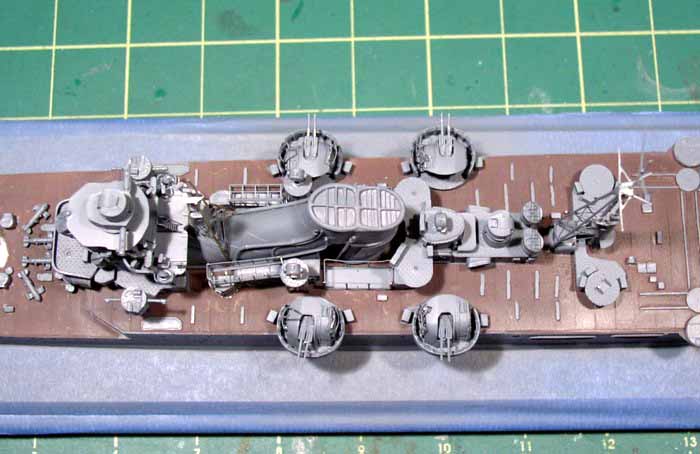
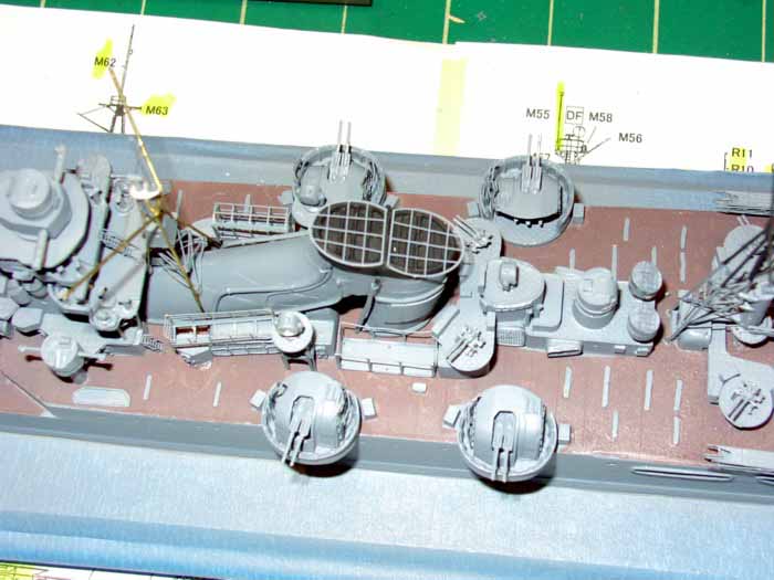
With the masts (thankfully) done, I turned to the loads of photo-etching
that graced the rest of the midships section. There were numerous
storage bins or crates on both sides of the funnel that carried lumber,
spare floats and spare wings for the scout planes (unfortunately I put
the aft baskets upside down). Also included were photo-etch parts
for the grills on the side of the heavy AA gun shields, as well as the
metal stops that prevented the AA guns from firing into the ship.
Once this was done, I attempted to use the very fine photo-etched hand
rails that go around the funnel, but after mangling a few pieces, elected
to keep my sanity and leave them off.
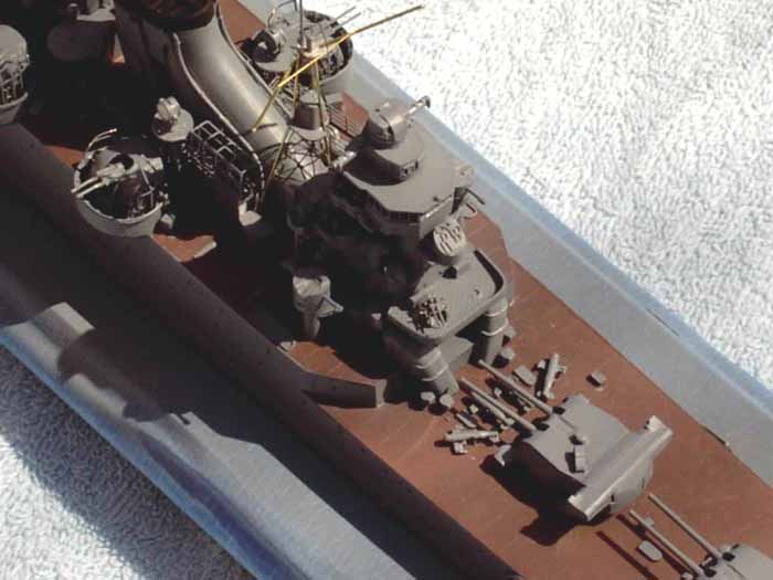
Next step was to add the white metal and photo-etch AA guns. Tone
carried six sets of these up through 1943. As we cue the broken
record, you can repeat after me: "The instructions were vague".
I was able to figure it out using some drawing that went with the plans
I had borrowed. Once I was able to get the guns together, I
glued them in place.
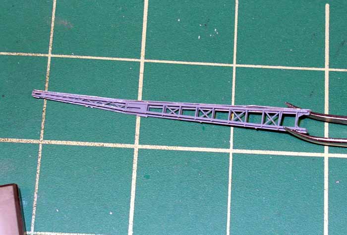
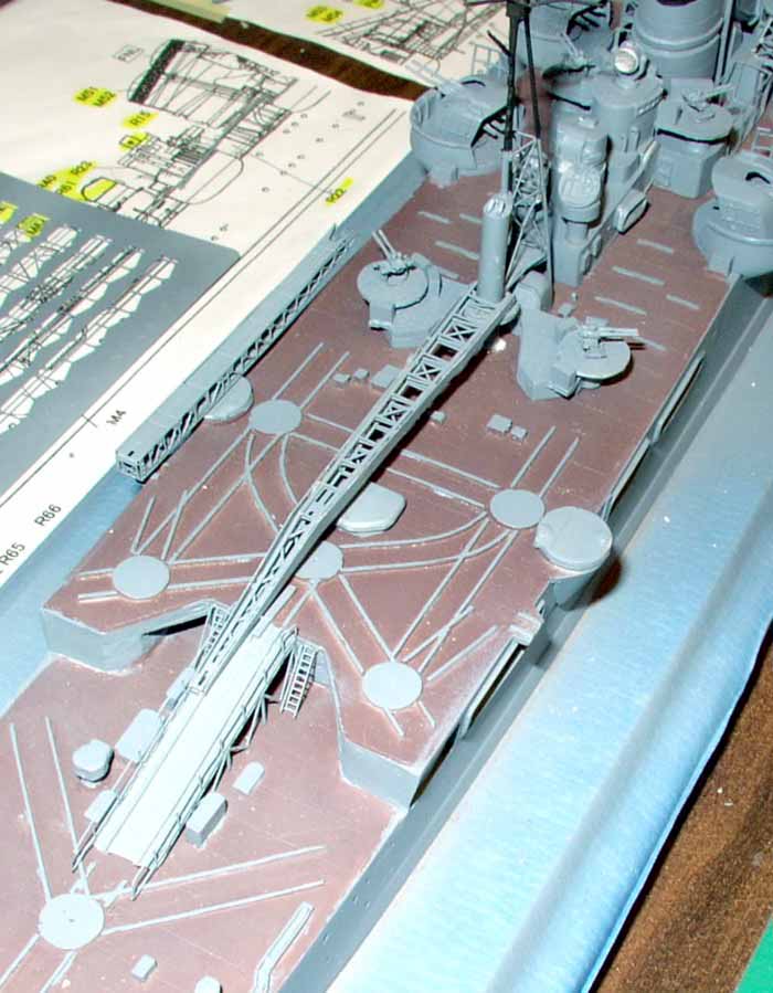
With the AA guns done, I added the resin and photo-etch ramp that connected
the lower and upper flight decks on aft portion of the ship.
This was pretty easy, although the resin part looked to be a little short.
I also added photo-etch inclined stairs on either side of the ramp.
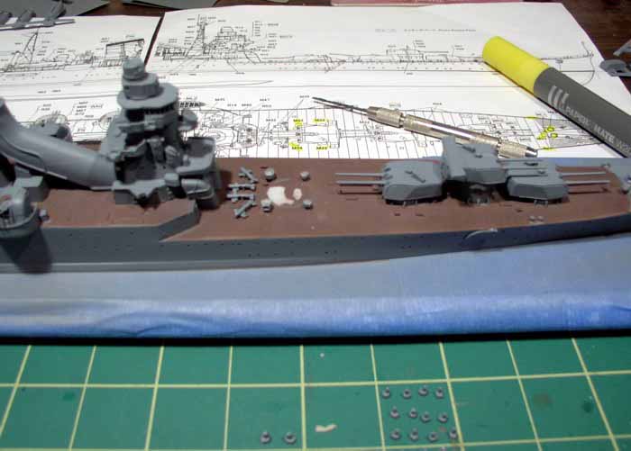
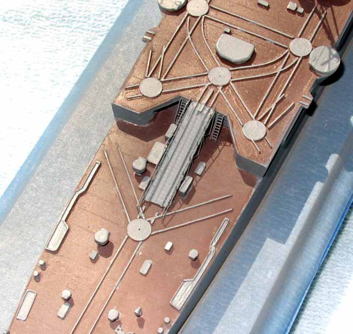
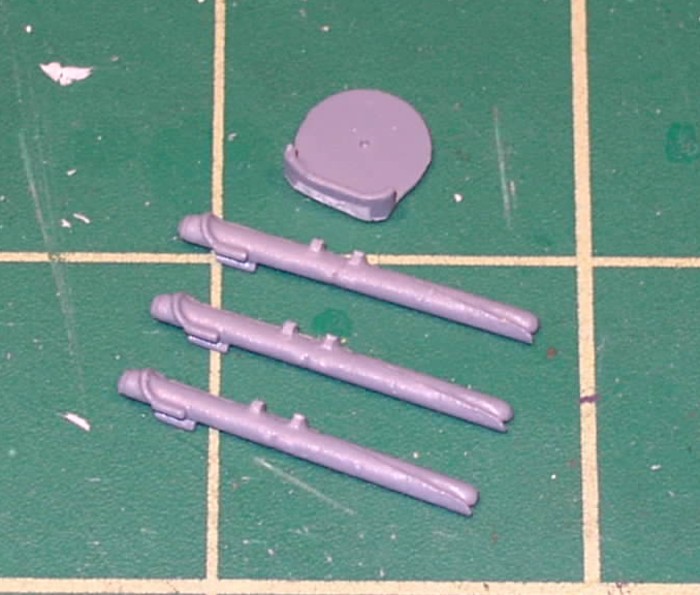
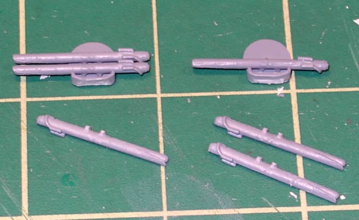
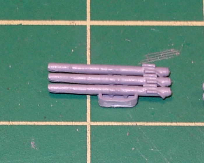
With the ramp in place, I assembled the torpedo tubes. Tone had
twelve tubes two sets of three on either side of the ship. Assembly
was straight forward, again helped by drawings. Unfortunately, the
prior builder had assembled the ship to the point where I was unable to
fit the forward most tubes into the ship. I elected to glue
the aft pair in place, and then covered the openings for the forward pair
with Kyrstal Clear. Once the ship was ready for final weathering,
I planned to paint them a light color to simulate canvas covers.
Now it was time to get into the serious photo-etch: the crane and the catapults.
As I studied the plans and got ready to move forward, I realized that some
photo-etch parts for the crane should have gone on BEFORE the mainmast
was assembled to the derrick. Since this wasn't possible, I
cut the parts - which represented the gear-wheel to turn the crane - in
two, glued them together around the derrick, then began to work on the
crane.
The crane consisted of two large pieces of photo-etched brass, then
numerous smaller pieces. The two main pieces formed the arm of the
crane - one part being the outside and the other being the lattice structure
on the inside. I folded the interior piece - which required
multiple folds - and tried attaching it to the outside part. I found
it was better to cut the outside part in two pieces instead of trying to
wrap it around the lattice part - so that is what I did.
To attached the crane to the derrick, there were two very small u-shaped
parts that had to be added to the photo-etched wheel. The ends of
the crane sit in these parts, which on the real ship allowed the crane
to move it's neck up and down. I attached the crane to these
parts, then super-glued them to the geared wheel. However,
after consulting the plans some more, I realized that the instructions
had really let me down. The geared wheel should have been put
on before the derrick was put on, AND in a different spot.
So, off came the crane, off came the geared wheel, out went my sanity.
I was able to get the wheel to lay flat enough on the main deck to then
re-glue the crane onto the ship. Once this madness was complete,
I added the pulleys to the derrick and to the crane, but decided to leave
the rigging until the end (so I could do touch up painting first).
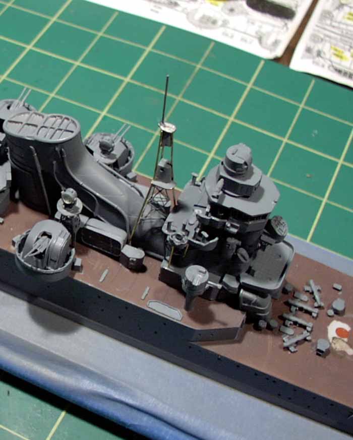
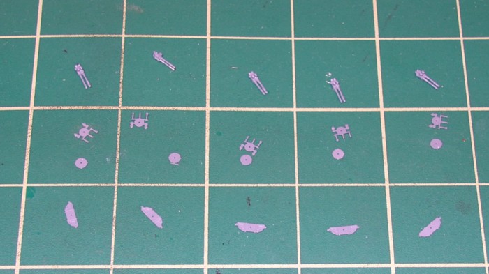
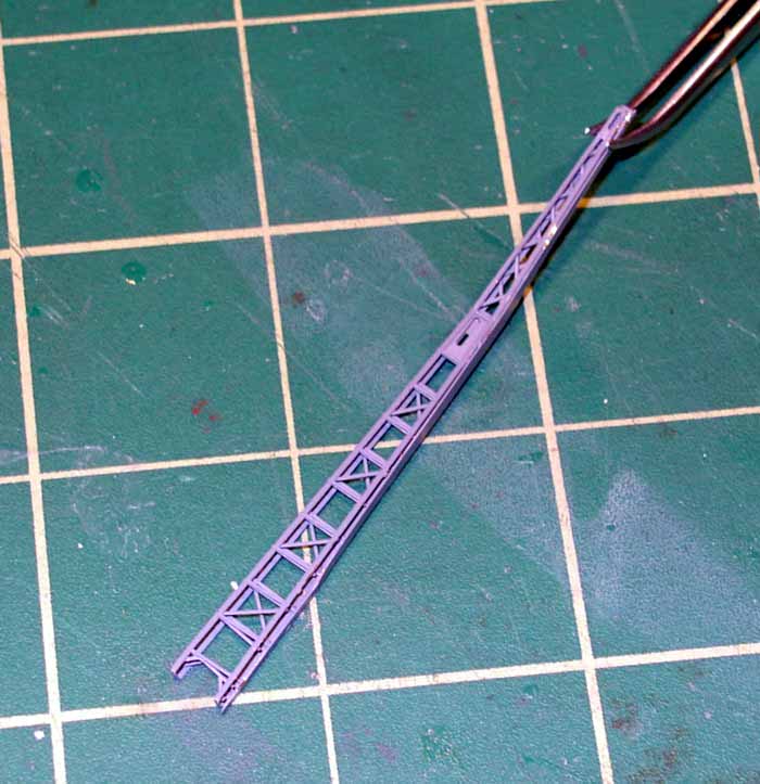
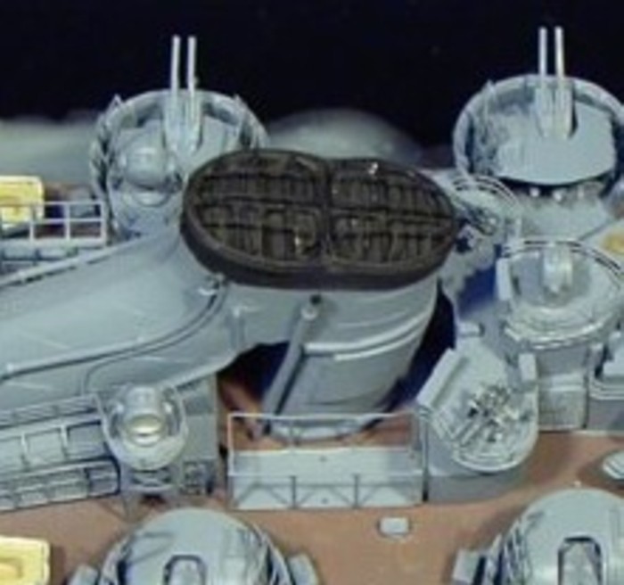
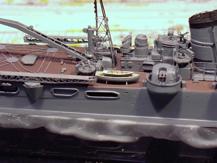
With the cranes complete, I moved onto the catapults. The
catapults actually had a small secondary drawing on a supplemental instruction
page, so they went together fairly straightforward. A white
metal part fits onto the bottom of the photo etch catapult, which is then
folded. Then, all the flywheels and smaller parts are added
as separate pieces (see picture below). Time intensive, but
worth the effort once done.
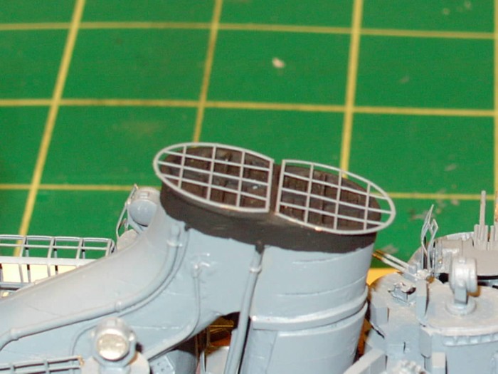
Ok...catapults, cranes, searchlight towers and the masts were done.
Looking around, it was time to tackle the funnel caps. I find
these particularly bothersome. But, using a rounded end of
a tool and making a few strategic snips, I was able to bend them into shape
and glue them on.
The cable reels follow the rest of the photo-etch parts: they consist
of multiple pieces. Once I had managed to snip them off
the sprue, I folded them, added plastic rod and glued on the reels on either
end, then attached them to the ship. This was one place where the
instructions were very clear. At this point, the main photo-etching
was done, so I moved onto adding railings. The railings that
come with the kit are of the "individual stanchion type. The modeler
I had inherited the kit from had included a set of Tom's ModelWorks 1/350
generic 2-bar railings. I elected to follow his lead and use these
instead of the kit supplied railings. I started with the forward
superstructure and worked my way backwards, until everything above the
main deck was railed.
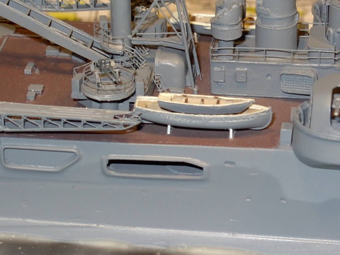
Before adding the railings to the main deck, I wanted to add the photo-etch
boat cradles and ships boats to the models. The cradles are
relief etched parts which are supposed to be folded in half, so you get
the etching on both sides. After repeated attempts to fold
the cradles, I found I was unable to do so, and decided to use plastic
strip instead (I found it interesting the Minekaze included double the
number of cradles required in the kit). Using the photo-etch
cradles as a guide, I outlined the area to be cut out on the plastic strip,
then carved them with an hobby knife. I made the appropriate
number of cradles and glued them to the deck. Once they were dry,
I painted them then added the ships boats.
Now that the boats were done, the model was "basically" finished.
As I had gone along, I had highlighted completed parts on the instructions.
I went back through the 'instructions' and checked to see if I had missed
anything. I added the photo-etch leadsman's platforms, the
torpedo cranes, the boat davits and pulleys for the foremost pair of boats
and some additional railing on a small platform on the foremast that the
instructions left vague. The kit doesn't include the
jackstaffs, so I added these from brass rod. As an additional
step, I cut some plastic sheet into small pieces and added them to the
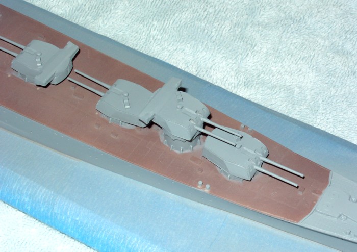
main turrets to help build up the blast bags. The blast
bags were then made out of acrylic gel medium.
With the blast bags done, the model itself was complete. The only
thing remaining were the floatplanes. Since I had decided to
build the Tone as circa Midway, I had pirated a Jake from a Tamiya Musashi
kit. I planned to build one Jake and two Pete's - which were
included with the kit. But, since I had read that none of Tone's
floatplanes had survived the Midway operations, I decided my Tone would
- for now - represent Tone in the late afternoon of June 4, 1942, sans
floatplanes. I sprayed a few thin coats of future
on the model, then lightly weathered it with oils. A few thin
coats of flat and some very light dry-brushing were followed by finishing
the "water".
| Conclusion: |

|
|
Minekaze filled a void in the 1/350 ship line when
it released the Japanese Heavy Cruiser Tone. Even though Yankee ModelWorks
has since released a kit of the Tone, that model is a 1944 version, while
Minekaze's version is a pre-1943 model. On the plus side, the
model is decently cast and appears to be an accurate representation of
Tone before her mid-war AA upgrade. Even with the poor instructions,
the majority of the kit went together fairly well and comes with an extensive
set of photo-etch. On the "con" side are two important things.
The first is the price. This kit retails for over $400.
While Tone was a fairly large ship, that price is more than some
resin battleships. The second and biggest "con" is the instructions
- they are totally inadequate for a model of this size and price.
At the end of the build, I had a myriad of photo-etched pieces and an assortment
of smaller white metal pieces left - the instructions should have accounted
for these, which didn't appear to be "extras".
This model certainly challenged and expanded my modeling
skills, and I certainly enjoyed building it. However, due to the
"cons", I can only recommend this kit to experienced builders - and then
only those with a very good set of references handy.
|
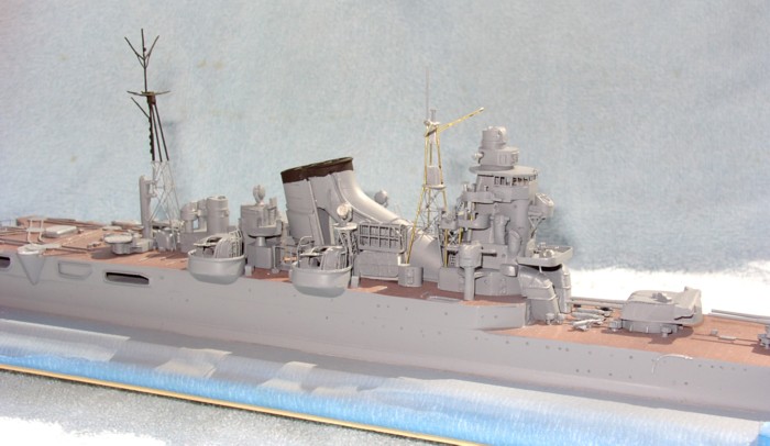
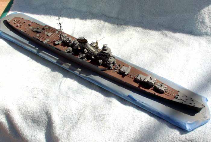
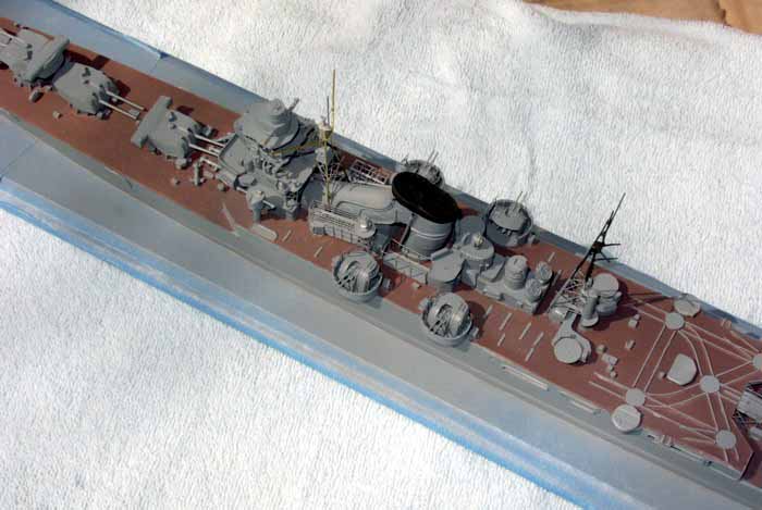
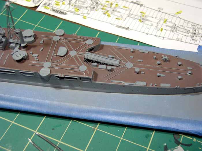
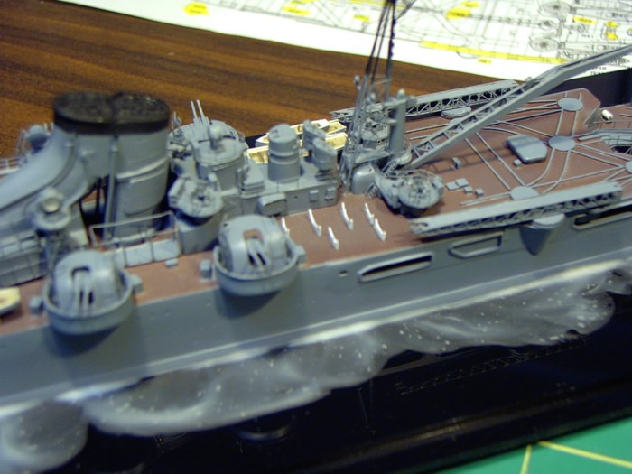
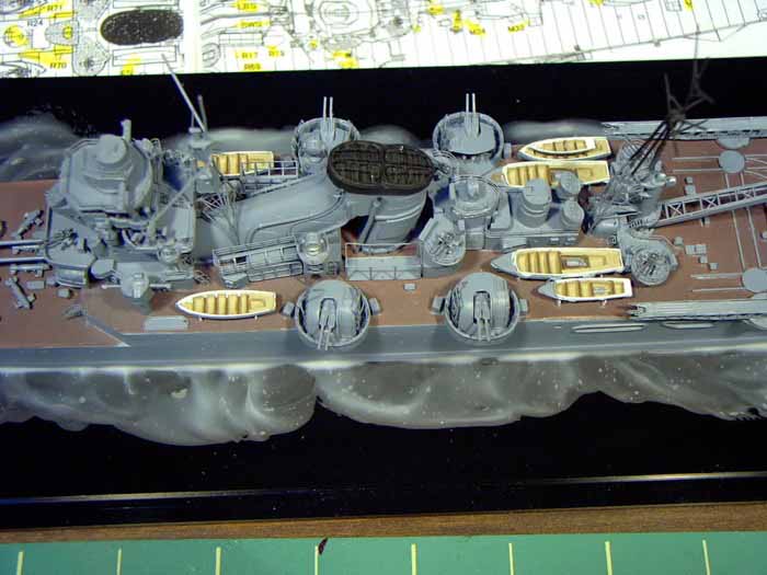
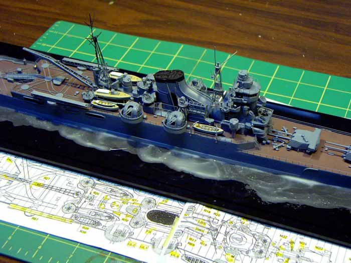
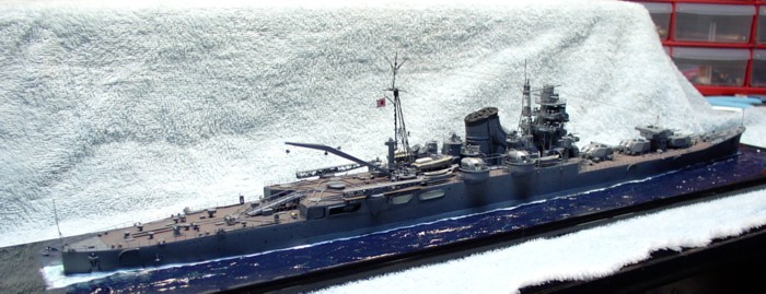
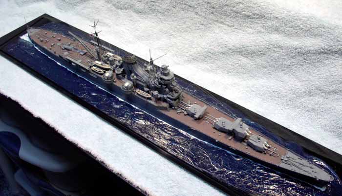
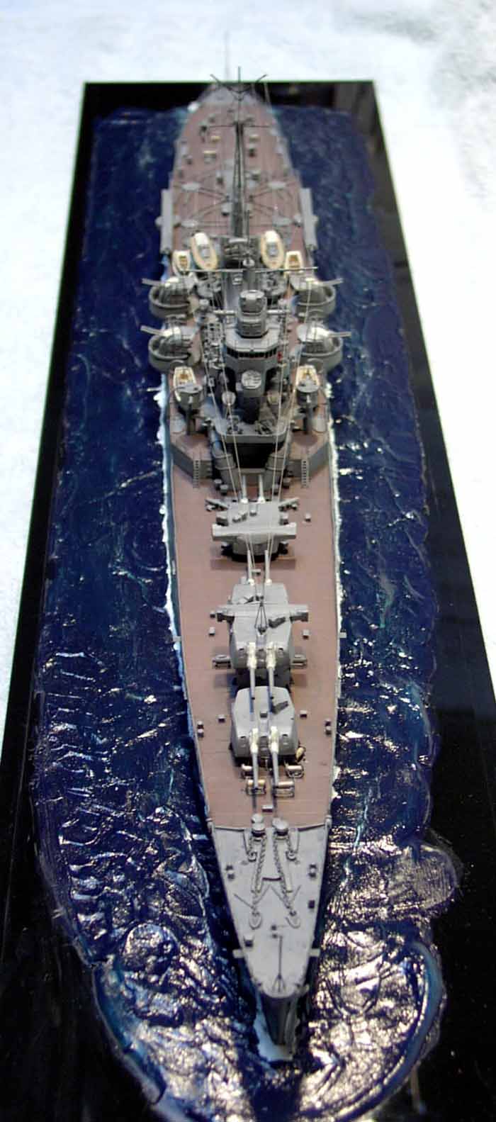
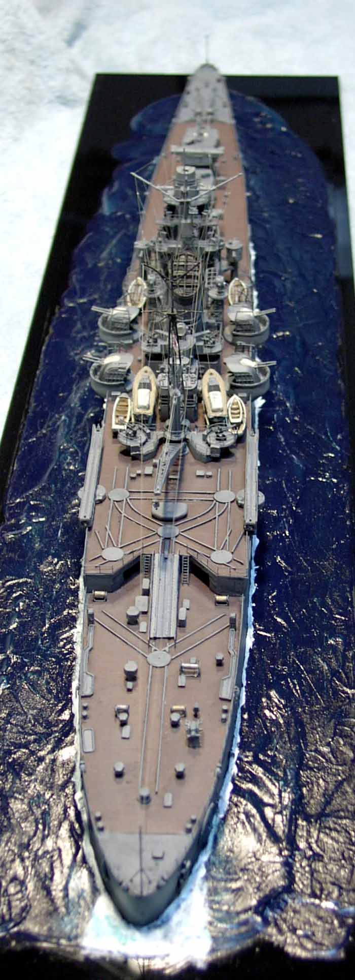
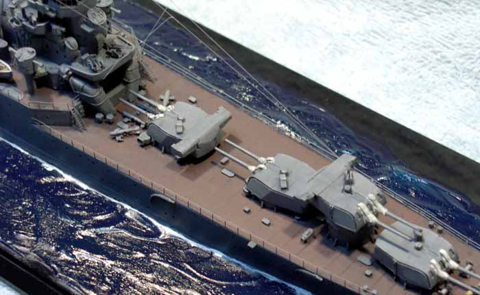
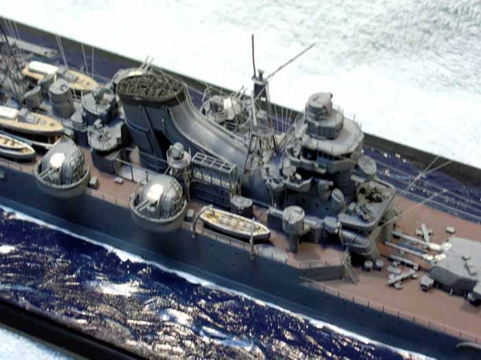
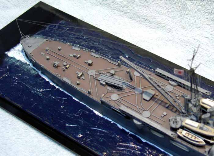
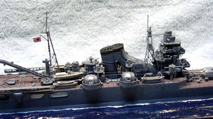
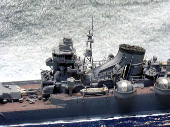
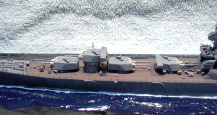
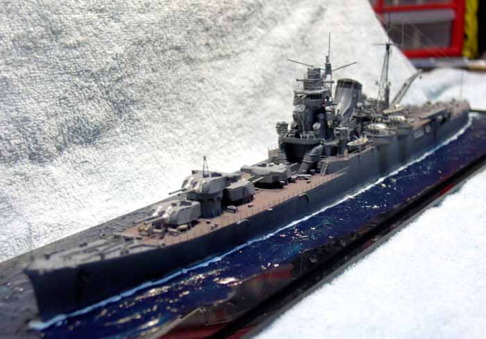
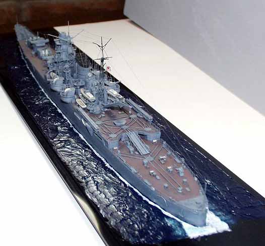
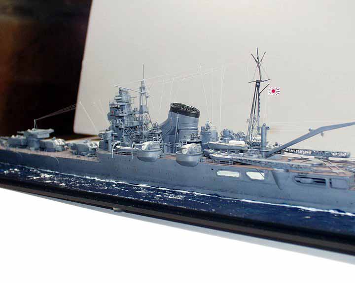
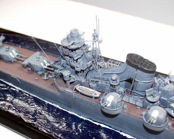
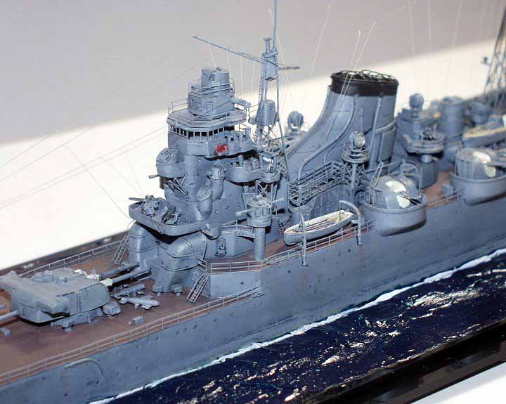
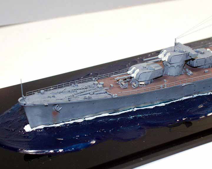
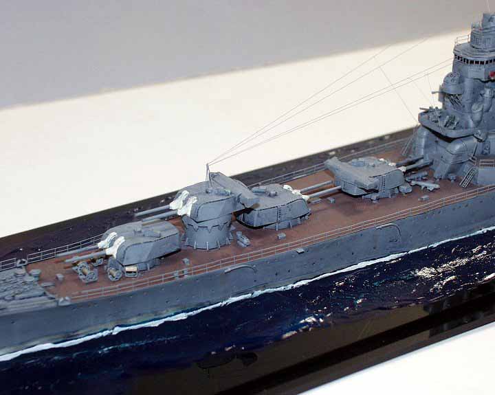
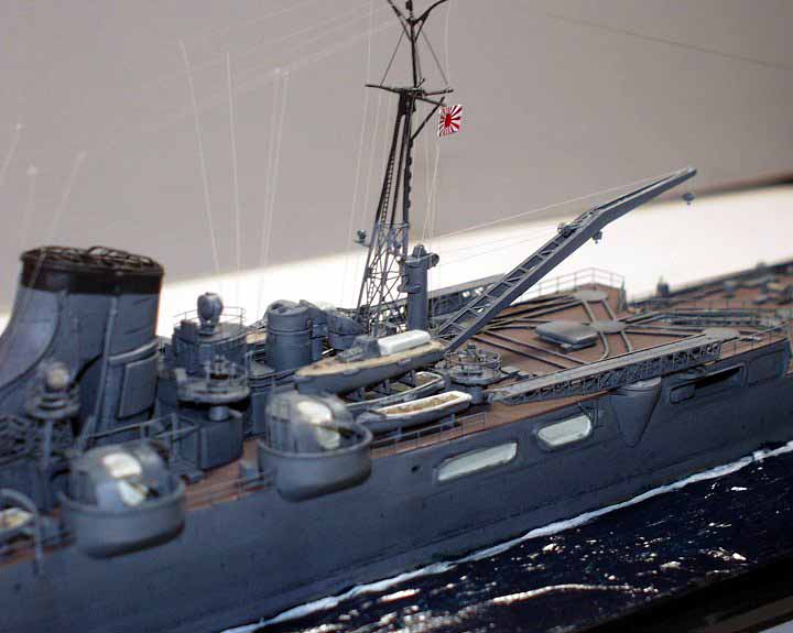
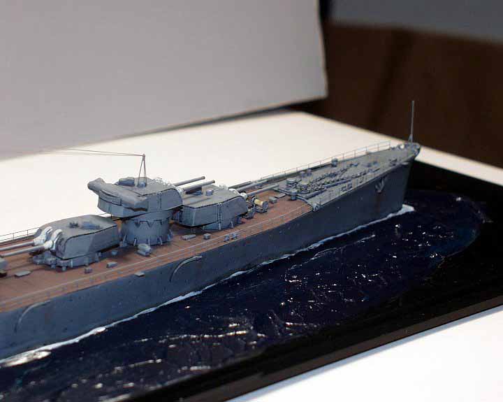
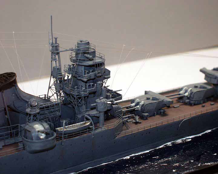
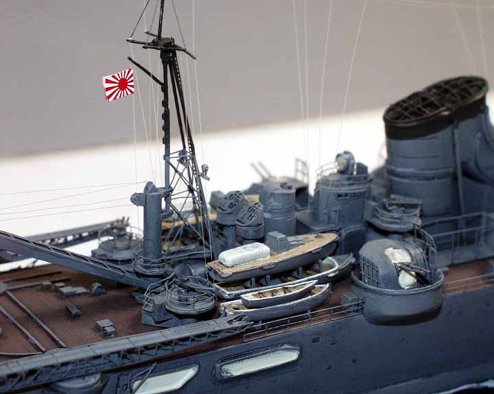
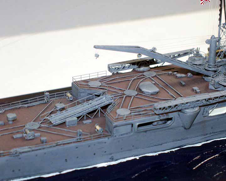
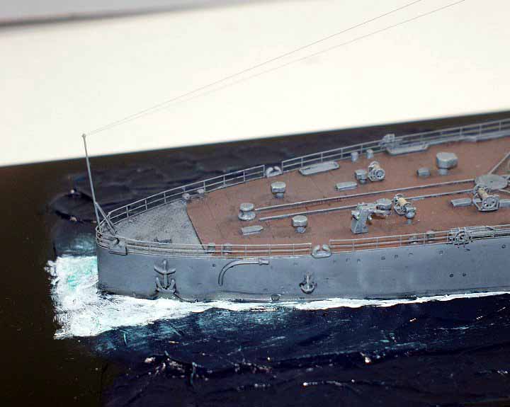
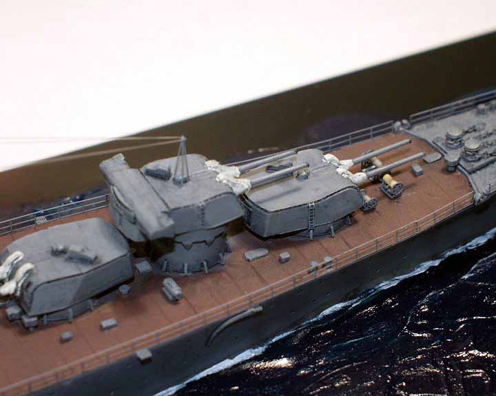
So, without any further babbling, here are some pictures of my finished
Minekaze 1/350 Imperial Japanese Heavy Cruiser Tone, sometime on the afternoon
of June 4, 1942...

© ModelWarships.com