| Birth, history and
operational service
After the building of the IJN Atago class heavy cruiser MAYA,
that I ended in 2005 after a three years work, I concentrated my attention
on a particular unit of the Mogami class, the MIKUMA, which life and
operational service were much shorter than the other twin vessels of the
same class, the Mogami, Suzuya and Kumano.
|
|||||||||||||||||||||||||||||||||||||||||||||||||||||||||||||||||||||||||||||||||||||||||||||||||||||||||||||||||||||||||||||||||||||||||||||||||||||||
 |
 |
 |
 |
 |
|||||||||||||||||||||||||||||||||||||||||||||||||||||||||||||||||||||||||||||||||||||||||||||||||||||||||||||||||||||||||||||||||||||||||||||||||||
| From this point of view, the new 155 mm gun (6.1 in), lighter
than the 203 mm, could have assured, if compared to the 8 in gun, a larger
number of guns fitted in the ships, respecting the displacement limits
of the Treaties; furthermore, its effective firing rate of 5 shells per
minute was far superior to the 2/3 shells per minute firing rate of the
203 mm gun; then, if we also consider that the weight of the triple 155
mm turrets full salvo was the same or often superior to that of the
double 203 mm turrets (the Mikuma, with her 15 155 mm 60 cal 3 Nendo Shiki
guns, could rain on the enemy ship a full salvo total weight of about 4.200
kilos of explosive and metal per minute, with a firing rate of 75 shells
per minute, while the heavier Atago class, for example, with its 10 203
mm guns, could rain a full salvo total weight of about 3.780 kilos per
minute and had a firing rate of 30 shells per minute), its quite easy
to understand that the birth of the Mogami class could be supported by
good presuppositions.
The 155 mm gun, notwithstanding its lower weight of the single shell and of the single explosive charge and lower maximum range than the 203 mm, could actually counter-balance its supposed inferiority with a higher firing rate and, consequently, with a superior fire volume; this was absolutely useful for the short distance naval engagement that was theorized by Yamamoto, who always tried to avoid the long distance naval battles, in which allied ships could have been superior. Furthermore, the fact that Japan certainly exhausted the possibility of launching more heavy cruisers, for the imposed naval limits, put a strong pressure on the IJN General Staff concerning the decision of building the four light cruiser of the Mogami class. But the new Yamamotos doctrine on cruisers employment, soon led the IJN General Staff to realize that the displacement limits of the Treaties would be easily exceeded if the new ships would have assured the performance expected by the Navy; a true proof of this was the total displacement of about 14.000 tons of the Mikuma in 1939, when the powers involved in the forthcoming 2nd world war had still put the observance of the Treaty limits away. With a length of about 200 metres and a beam of about 20 mt, the Mikuma was a heavy armed cruiser, with a beautiful line, a huge hull and little superstructures, if compared to the other Japanese cruisers design of that era. It was a fast ship and its AA armament was composed by four 127 mm high angle gun in twin mountings, located in the center of the ship and four type 96 25 mm twin MG, located in the center superstructure that enclosed the big funnel, fitted for turning the smoke out that was produced by 10 Kampon boilers, with a maximum power of 152.000 shp. Another two 13 mm twin MG were located in a platform that was in the front part of the main tower, just behind the 155 mm turret no. 3. Furthermore, the Mikuma was armed with twelve 610 mm (24 in) torpedo tubes, in triple mountings, mounted on the upper deck at the after end of the superstructure, fitted for firing the powerful oxygen-propelled Long Lance torpedoes, one of the worst certitudes that allied ships must face during the Pacific War. The extensive use of the light alloy and electric welding, instead of the riveted plates, gave the opportunity of building lighter ships, allowing, in consequence, the fitting of a higher number of guns; nevertheless, this building lightening that was pushed over the limits of an acceptable and unavoidable risk margin, caused such a structural weakness that after the 4th Fleet Incident occurred on September 1935, when a huge typhoon struck the 4th Fleet with Mikuma and Mogami also, the heavy damages caused by the strong winds and very high wakes to the ships structures, led the IJN General Staff to completely revise all the ships building projects and building process, with the main aim of recovering the structural safety of the ships. |
|||||||||||||||||||||||||||||||||||||||||||||||||||||||||||||||||||||||||||||||||||||||||||||||||||||||||||||||||||||||||||||||||||||||||||||||||||||||
 |
 |
 |
 |
 |
|||||||||||||||||||||||||||||||||||||||||||||||||||||||||||||||||||||||||||||||||||||||||||||||||||||||||||||||||||||||||||||||||||||||||||||||||||
 |
 |
 |
 |
 |
|||||||||||||||||||||||||||||||||||||||||||||||||||||||||||||||||||||||||||||||||||||||||||||||||||||||||||||||||||||||||||||||||||||||||||||||||||
|
After the sea trials, Mikuma and Mogami showed some serious structural deficiency; the wrong weights subdivision, with an excess of weight coming from the superstructures and the armament compared with the hull and machinery, caused a rise of the barycentric height and a lacking in athwartship stability; in consequence, there was a dramatic rolling and the ship couldnt be a good shooting platform. Furthermore, during the first 155 mm firing tests, the strong vibrations and recoils caused by the 155 mm broadsides, caused some hull distortions and infiltrations of water in the welded plates. Then, also the heavy damages caused by the typhoon of September 1935, finally led the Mikuma to enter the Kure dockyard for an heavy reconstruction and refit that took from April 1936 to October 1937. The interior main structures were strengthened and the welded plates were replaced by riveted plates; then some plates were added on the bottom of the keel and the 127 mm AA gun deck was reinforced near the gun turrets; furthermore, the reconstruction eliminated the connections between the barbettes of the no. 3 and no. 4 155 mm gun turrets and the 127 mm gun deck, to prevent the effect of the hull distortion caused by the 155 mm gun firing. Then, new bigger bulges were added over the old ones, so that both beam and displacement increased, together with a lowering of the barycentric height that caused an improvement of the athwartship stability; then, the main mast was also lowered. In 1937, the heavily modified Mikuma was definitively commissioned and formed the famous 7th Cruiser Division of the Imperial Japanese Navy together with the Mogami, Suzuya and Kumano. The apparition of the four Mogami class units was not a real surprise for the western powers, that actually were informed about the strategic plans of Japan; their answers were not to be expected so long. In fact, Great Britain drew up the eight light cruisers of the Southampton class, while the United States commissioned the nine Brooklyn class light cruisers, both classes armed with 155 mm guns. This difference in navy forces, 17 vs 4, led the IJN General Staff to partially revise the employment doctrine of light cruisers; this doctrine did not lose its general validity, but it would have been revised in the light of this new and unfavourable (for Japan) intercourse of the naval forces. For this and other reasons, in 1939 the IJN General Staff decided to modify the four Mogami again, fitting the 203 mm guns instead of the 155 mm guns and turning them into heavy cruisers, with the main aim of counterbalancing the cropped up inferiority in numbers with a heavier power of the single Japanese unit than the enemy unit. Regarding the operational service, in 1937 1938 the Mikuma was incorporated in the 7th Cruisers Division and used in Chinese waters during the Chino-Japanese war. After the great reconstruction of 1939 and the consequently modifying as an heavy cruiser, the Mikuma was used in Indo-China in 1941, to put pressure to the Vichy France government in that territory. In July of the same year, the Mikuma was supporting the advancing of the Japanese troops in Indo-China, fighting against the Vichy France army, but this was not a bloody combat because of their political opportunism dictated by the fact that they had a common allied, the Hitlers Germany. After the raid against the US naval base of Pearl Harbour of December 7th 1941, the Mikuma was employed with the 7th Cruisers Division to support the Japanese landing forces in Malaya, Borneo, Sumatra, Java, and Andamane Islands. Between the 28th of February and 1st of March 1942, the Mikuma and Mogami sank the US cruiser USS Houston and the Australian cruiser Perth, off Batavia, soon after the important Japanese victory in the battle of Java See. On April 1942, the Mikuma took part in the Japanese naval attack force against the allied merchant ships in the Indian Ocean, and after a short period in the dockyard for a little refit, in May 1942 she was ready to fight again. On June 1942 she took part in the battle of Midway, where the Mikuma saw her end of life. The 29th of May of the same year, the 7th Cruisers Division was ordered to leave from Guam to escort the Japanese convoys that would have landed in the isle of Midway; the 5th of June the Mikuma was ordered to shell the isle for supporting Japanese landing troops, but soon the order was cancelled and the Mikuma, together with Mogami, retreated to their base. During the return voyage, the Japanese naval force was intercepted by the US submarine USS Tambour, and during the agitated Japanese diverting actions to avoid the torpedoes danger, the Mogami and Mikuma collided, with heavy damages on the Mikuma. In spite of this, the two cruisers went on their way at a low speed, so that they soon were sighted by the dive-bombers and torpedo-bombers from the US carriers Yorktown, Hornet and Enterprise. The attack arrived soon and was deadly for the Mikuma: hit by bombs and by a US plane that crushed near the aft no. 4 155 mm gun turret, the cruiser soon became a burning wreckage and sank the night of June 6th 1942, about 500 miles west-north-west of Midway, bringing lots of men to the bottom with her. |
|||||||||||||||||||||||||||||||||||||||||||||||||||||||||||||||||||||||||||||||||||||||||||||||||||||||||||||||||||||||||||||||||||||||||||||||||||||||
 |
 |
 |
 |
 |
|||||||||||||||||||||||||||||||||||||||||||||||||||||||||||||||||||||||||||||||||||||||||||||||||||||||||||||||||||||||||||||||||||||||||||||||||||
 |
 |
 |
 |
 |
|||||||||||||||||||||||||||||||||||||||||||||||||||||||||||||||||||||||||||||||||||||||||||||||||||||||||||||||||||||||||||||||||||||||||||||||||||
 |
 |
 |
 |
 |
|||||||||||||||||||||||||||||||||||||||||||||||||||||||||||||||||||||||||||||||||||||||||||||||||||||||||||||||||||||||||||||||||||||||||||||||||||
 |
 |
 |
 |
 |
|||||||||||||||||||||||||||||||||||||||||||||||||||||||||||||||||||||||||||||||||||||||||||||||||||||||||||||||||||||||||||||||||||||||||||||||||||
| Building the kit
The Mikumas kit is the classic 1:700 Tamiya; the quality standard of
the Japanese firm is full confirmed by this kit, also if its not at the
same level as the Rodneys and Nelsons kits, the Hoods kit or the Prinz
Eugens kit, that were unbelievable detailed.
|
|||||||||||||||||||||||||||||||||||||||||||||||||||||||||||||||||||||||||||||||||||||||||||||||||||||||||||||||||||||||||||||||||||||||||||||||||||||||
 |
 |
 |
 |
 |
|||||||||||||||||||||||||||||||||||||||||||||||||||||||||||||||||||||||||||||||||||||||||||||||||||||||||||||||||||||||||||||||||||||||||||||||||||
 |
 |
 |
 |
 |
|||||||||||||||||||||||||||||||||||||||||||||||||||||||||||||||||||||||||||||||||||||||||||||||||||||||||||||||||||||||||||||||||||||||||||||||||||
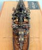
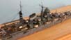
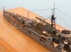
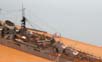
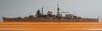
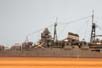
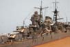
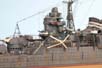
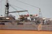
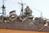
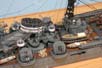
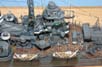
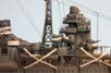
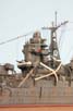
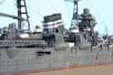
| Starting from the Tamiyas original part of the main tower
bridge structure, I cut all the wrong parts and I scratch-built the compass
bridge deck, the upper bridge and fire command platform; the windows on
the compass bridge deck were simulated by cutting a piece of hanging ladder
of the right measure, to which I glued a thin stripe of transparent acetate
(the material that in Italy we find usually in the brand new shirt boxes).
Also the frontal platform for the 13 mm aa machine guns, the signal platforms,
the type 95 director tower, the type 94 rangefinder tower with its 6 mt
rangefinder, the semaphore signal stations, the 12 cm and 18 cm binoculars,
the type 92 torpedo fire command panels, the type 91 model 3 torpedo directors,
the type 94 searchlight control installations, the two type 91 high angle
director towers, were all scratch-built, as for the remaining details of
the main tower bridge structure that would be impossible to reckon up one
by one.
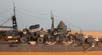
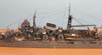
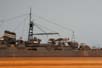
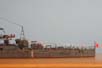
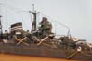
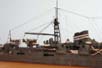
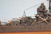
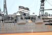
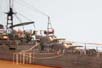
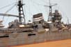
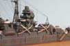
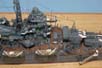
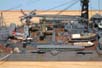
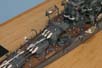
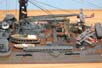
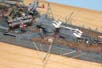
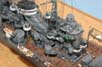
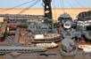
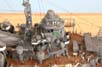
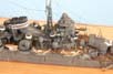
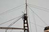
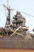
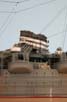
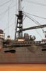
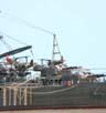
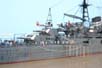
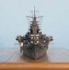
The engine room ventilation cowls (13) have been made by using the Gold Medal Models photoetched nets for the modern ships, cut and shaped in the right way. The foremast was made by using the photoetched part from Pit-Road, to which I added the anemometers, the RDF room with its platform and ladder, the RDF antenna, the signal lights (made by a very little drop of Kristal Klear), the yardarm and all the other little details. As soon as Ive finished the construction of the main tower bridge structure and the foremast, I added the two photoetched 13 mm aa twin machine guns (Lion Roar), the ammunition boxes, the searchlights, the binoculars, the rangefinder and all the railings. After that, I started to build the funnel and the central structure, where the light artillery, the four 25 mm aa twin machine guns, was located. The big funnel was composed by two separate parts that joined together on the top of the funnel, just under the cap (as other Japanese vessels of that period); the shape of the kit funnel was wrong, and the engine room ventilation cowls located on its base were wrong too. For this reason, I had to scratch-build all the low part of the funnel, the ventilation cowls and all the auxiliary and external pipes (12), so that they were not jointly liable with the funnel but, on the contrary, they had a true 3D effect that was unknown before. Then I added al the photoetched walkways on the funnel, the two sirens, the protection grill on the funnel cap (made by copper wires) and the long hanging ladder that started from the base of the funnel, just behind the main tower bridge structure and arrived to the funnel cap. As soon as I finished the funnel, I completely re-built the structure around it for the 25 mm aa machine guns, the passage connecting trenches and ladders from this structure to the funnel and the deck and the three circular platforms with braces structure for the 110 cm searchlight. Then I glued the 25 mm mg with ammunition boxes (all from Lion Roar), with the hanging ladders and railings. Then I glued this section to the hull, being careful to the exact alignment between the first and the second section and also between the two sections and the lengthwise half line of the deck. The third section, that one of the aft structure and mainmast, was scratch-built all the same; the reason was because the kit aft structure was wrong, as concerning the shape of it (or better, the shape was right for the Mikuma in 1942, at her loss date, but as I want to depict the cruiser in 1938, the shape of this structure could have been quite different), and because the kit mainmast was out of scale and too poor. |
|||||||||||||||||||||||||||||||||||||||||||||||||||||||||||||||||||||||||||||||||||||||||||||||||||||||||||||||||||||||||||||||||||||||||||||||||||||||
 |
 |
 |
 |
 |
|||||||||||||||||||||||||||||||||||||||||||||||||||||||||||||||||||||||||||||||||||||||||||||||||||||||||||||||||||||||||||||||||||||||||||||||||||
 |
 |
 |
 |
 |
|||||||||||||||||||||||||||||||||||||||||||||||||||||||||||||||||||||||||||||||||||||||||||||||||||||||||||||||||||||||||||||||||||||||||||||||||||
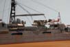
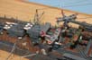
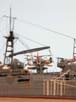
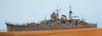
| For the mast I used different diameter brass rods; then
all the small details were added, as concerning the anemometers, navigation
lamps, platforms, ladders, two small searchlights, the crane for the seaplanes
and for the boats (from Lion Roar) and the rotation mechanism of the crane
around its central pivot, played by the mast. This mechanism was composed,
in the real ship, by a big cog-wheel that was moved by another more little
cog-wheel; this last was connected, by a vertical shaft, to an engine that
was located in the aft structure.
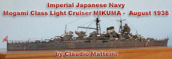
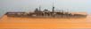
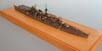
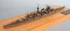
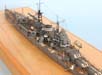
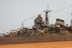
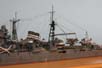
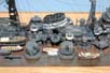
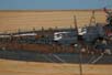
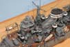
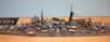
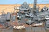
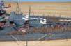
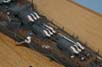
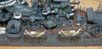
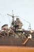
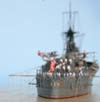
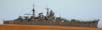
As I had lots of very strange spare parts in my private spare parts bank, I found out some extra-little watches gears that were absolutely right to represent the cog-wheels mentioned above. Then I glued the aft structure and the mainmast to the deck and checked the exact alignment of this section to the previous ones; as soon as I did it, I started to build the 155 mm gun turrets, made by resin starting from a modified master, with the brass barrels from Clipper Models, the 127 mm HA guns from Lion Roar, heavily modified with scratch-built parts (the 127 mm guns turrets are four, and every turret is composed by 54 parts), the cutters and motor boats, the three embarked seaplanes (two Dave and one Alf) with connecting rods between the wings, seats, etc.., the Kure type 2 model 3 catapults, the aircraft deck rails and turntable, the railings, the stanchions with rigging, the jack staff and ensign staff and so on. Then, some dozens of wooden boxes full of provisions for the crew and materials for the on board living have been added together with about 300 photoetched men (from Eduard). If in my previous model, the heavy cruiser Maya, I attended about 3500 parts for the total construction, for the Mikuma I couldnt remember at all, because at a certain time of the model building, I had no wish to count all the pieces; but Im sure to have exceeded that figure, because there was much work and scratch-building on the Mikuma than the Maya.. I know its crazy or impossible to understand, but its the only way, to me, to amuse myself when making a ship model! I depicted the Mikuma as it was in August 1938, during her staying in the Bungo Strait and Ise Wan areas. |
|||||||||||||||||||||||||||||||||||||||||||||||||||||||||||||||||||||||||||||||||||||||||||||||||||||||||||||||||||||||||||||||||||||||||||||||||||||||
 |
 |
 |
 |
 |
|||||||||||||||||||||||||||||||||||||||||||||||||||||||||||||||||||||||||||||||||||||||||||||||||||||||||||||||||||||||||||||||||||||||||||||||||||
 |
 |
 |
 |
 |
|||||||||||||||||||||||||||||||||||||||||||||||||||||||||||||||||||||||||||||||||||||||||||||||||||||||||||||||||||||||||||||||||||||||||||||||||||
| Acknowledgements
I would like to express my sincere thanks to those who have helped me
both directly and indirectly in collecting materials and information for
this model and to the friends who have offered advices on construction
process.
|
|||||||||||||||||||||||||||||||||||||||||||||||||||||||||||||||||||||||||||||||||||||||||||||||||||||||||||||||||||||||||||||||||||||||||||||||||||||||
 |
 |
 |
 |
 |
|||||||||||||||||||||||||||||||||||||||||||||||||||||||||||||||||||||||||||||||||||||||||||||||||||||||||||||||||||||||||||||||||||||||||||||||||||
 |
 |
 |
 |
 |
|||||||||||||||||||||||||||||||||||||||||||||||||||||||||||||||||||||||||||||||||||||||||||||||||||||||||||||||||||||||||||||||||||||||||||||||||||
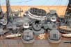
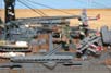
Photoetching and resin parts used on
the 1:700 Mikuma
Bibliography
|
|||||||||||||||||||||||||||||||||||||||||||||||||||||||||||||||||||||||||||||||||||||||||||||||||||||||||||||||||||||||||||||||||||||||||||||||||||||||
More
of Claudio Matteini's work.
Updated 2009

© ModelWarships.com