|
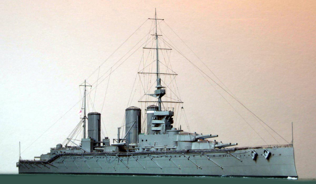
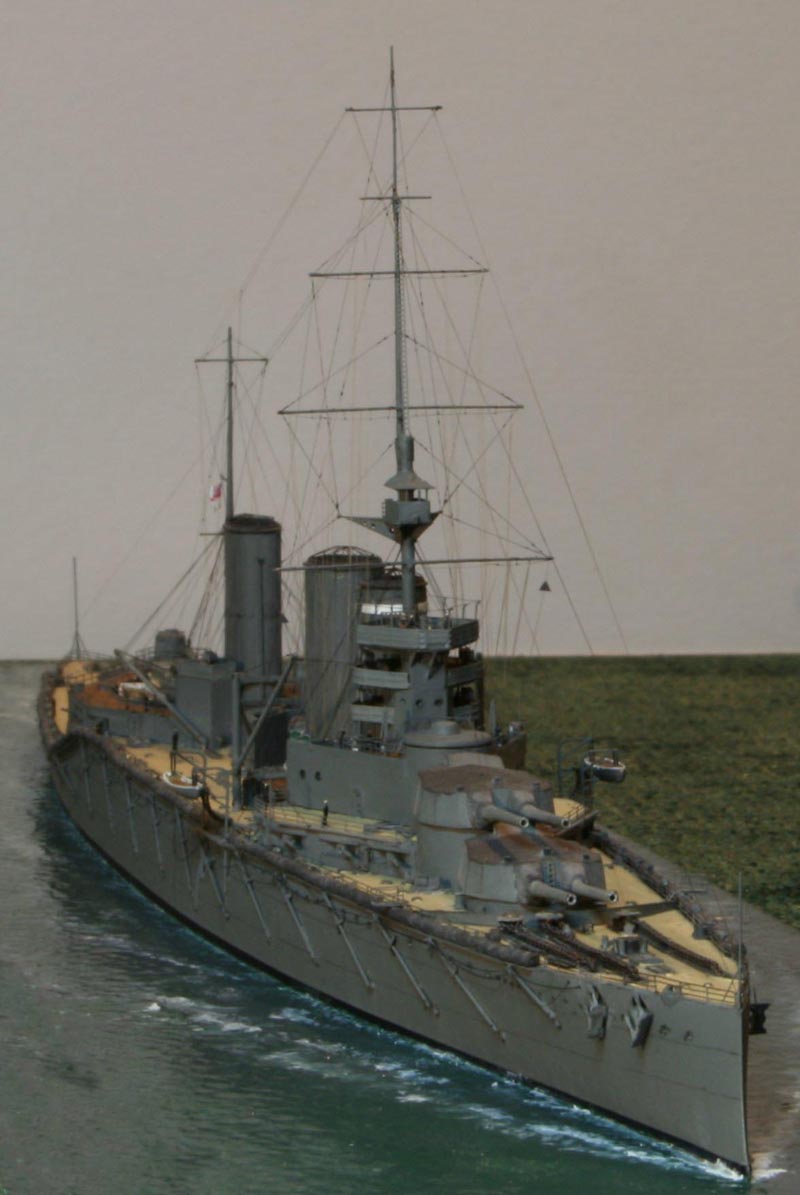
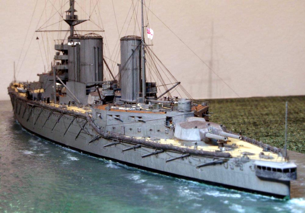
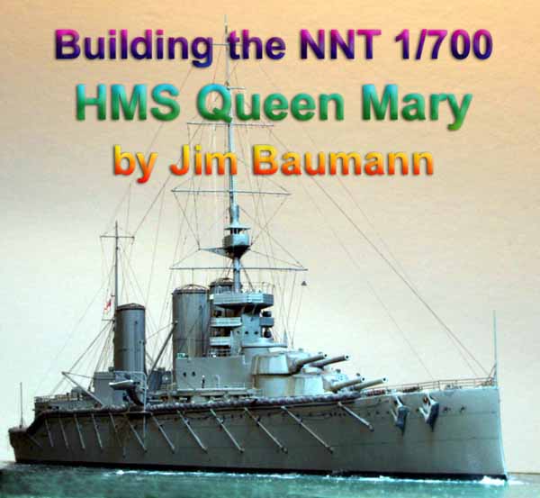
Generally, battlecruisers were similar in layout and armament to battleships but with significantly less armor allowing for gains in speed. The concept was conceived by the Royal Navy's Admiral " Jackie" Fisher who believed " that speed is the best protection". Fisher's idea centered on battle cruisers operating with the fleet, the intention being that they would hunt down enemy cruiser squadrons and evade the battleships. To enable these large ships to achieve the speed advantage sought the design concept deviated from the standard practice of providing a ship with sufficient armor to protect against its own guns. The weight saving from the reduced armor allowed more powerful engines to be fitted. However, different nations built to widely different designs. Some battle cruisers were smaller than battleships while others were larger than contemporary battleships. The chief similarity was the role specification. They were designed to hunt down and outgun smaller warships and outrun larger warships that they could not outgun. The Lion class Battle cruisers were an improved development on the previous Invincible and Indefatigable classes of first generation Battlecruisers. HMS Queen Mary is often listed as the third member of the Lion class although a better description would be a half-sistership as she was fitted with more powerful machinery, different secondary armament disposition, carried a sternwalk as well as the center funnel being round the easiest visual clue to differentiate her from HMS Lion and Princess Royal. Queen Mary was the only warship fitted with the 'Pollen' gunnery control system. Her 13.5-inch guns were considered to be the most accurate in the British fleet. SPECIFICATIONS
1st Battlecruiser Squadron Grand Fleet.
Upon commissioning, she joined the 1st Battlecruiser Squadron. On 28 August 1914 she took part in the Battle of Heligoland Bight. At the Battle of Jutland she had fired about 150 13.5 in shells and scored 4 hits on the the German Battlecruiser SMS Seydlitz , nevertheless the Seydlitz hit back. Queen Mary was first hit above the right gun on 'Q' turret; which put that gun out of action whilst the left gun kept firing. She took some more 12 in shell hits on her her forward 'A' and 'B' turrets followed by another hit on 'Q' turret. The forward magazine exploded, the ship listed to port, more explosions followed as the ship was sinking. All but twenty of her 1,275 crew were lost. |
||||||||||||||||||||||||||||||||||
| Building the Model.
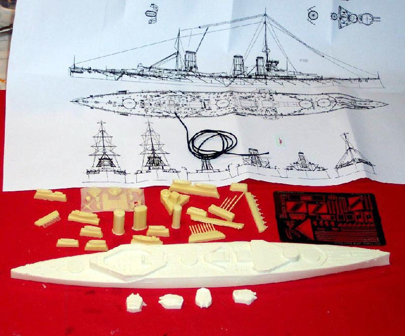
Well known German ship resin kit manufacturer NNT has produced an excellent starting point for building a 1/700 scale model of this majestic vessel . Along with various book and web resources I used primarily the excellent large scale plans supplied with the John Robert's Book Battlecruiser. This has, along with the usual plan and side elevation some very helpful cross-section at various stations as well as a very explanatory large perspective drawing of the bridge-tower structure. I cross-referenced these plans with as many photos as I could find from both electronic as well as printed sources. The ships short career is, I believe, reflected in the relative scarcity of close-up photos! In my opinion,-- had this same plan been used in the construction of the master model...-- the construction time of my model would have been cut dramatically...! The reason for this is that the huge amount of cast on deck detail is all in the correct place is however all flat! Study of plans in side elevation and cross-section shows the many flat squares on the deck casting to be actually square and round mushroom vents of varying sizes and heights, small deckhouses, tackle bins, lockers and skylights which are all very much three-dimensional. I made all these using styrene stock, paper and brass wire etc . The lower position (wartime) boat crutches were all removed and their reinforced skid positions marked in with tape strips. I added the coaling winch drums to the bulkheads as well as made 4 x winches for the correctly placed but flat positions. All the entirely missing cable reels were either scratch built or WEM Pro series resin items. |
||||||||||||||||||||||||||||||||||
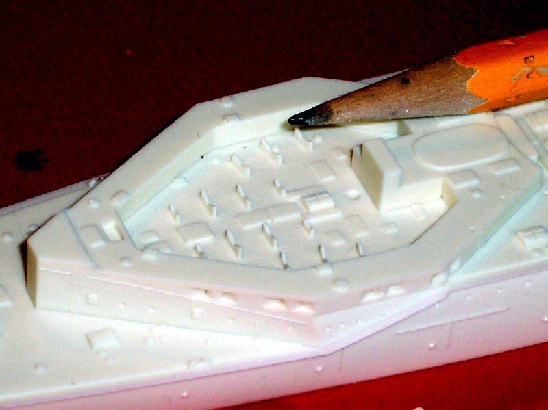
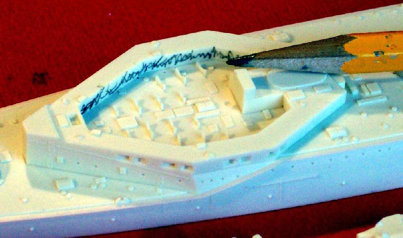
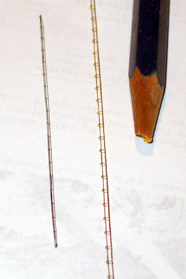
| I drew in hinges and clips on all lockers with a very sharp
pencil and outlined many of the deck fittings in pencil to sharpen up the
final effect.
The above comments in no real way detract from the overall excellence of the product which I would highly recommend to anyone wishing to build a model of this great but flawed warship. |
Click image
to enlarge |
|||||||||||||||||||||||||||||||||
 |
||||||||||||||||||||||||||||||||||
| This high quality kit has flawless casting- but there are
some areas that required research and further work to be undertaken to
allow me to be satisfied!
The first major area that required work was the aft casemate/ boat stowage area. The outline plan view footprint was spot on, however the walkway around the top on the real ship was supported on pillars giving an undercut not represented in the kit casting this area being solid.... |
 |
|||||||||||||||||||||||||||||||||
 |
||||||||||||||||||||||||||||||||||
| I attacked this problem by first making a paper tracing to use as a template for the new supported deck. | 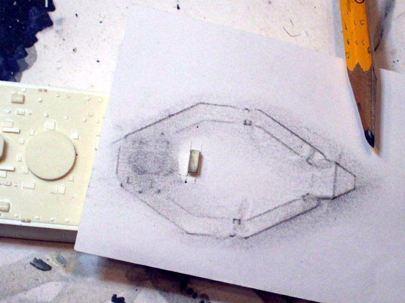 |
|||||||||||||||||||||||||||||||||
 |
||||||||||||||||||||||||||||||||||
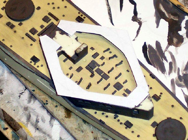
| Then the offending (to my eye!) solid resin area was ground
away with a motor tool , taking care not to penetrate the hull sides or
to go too deep-- a drum shaped grind stone was essential for this operation.
The outer 'walls' were lined with Evergreen strip, painted and thereafter it was time to view the fruits of my labors by applying the new paper deck! Once glued glued in place with the CA glue fully cured the excess was trimmed off, and sanded flat with very fine sandpaper, as the CA glue lifts the grain of the paper very slightly. The higher level aft was created using more paper and the stairway apertures onto both sides of the quarterdeck were cut through also at this stage Stairway well was cut in, tackle boxes and other detail added |
 |
|||||||||||||||||||||||||||||||||
 |
||||||||||||||||||||||||||||||||||
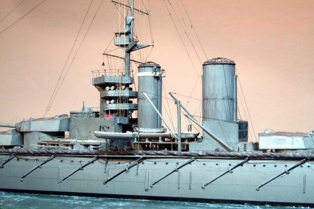
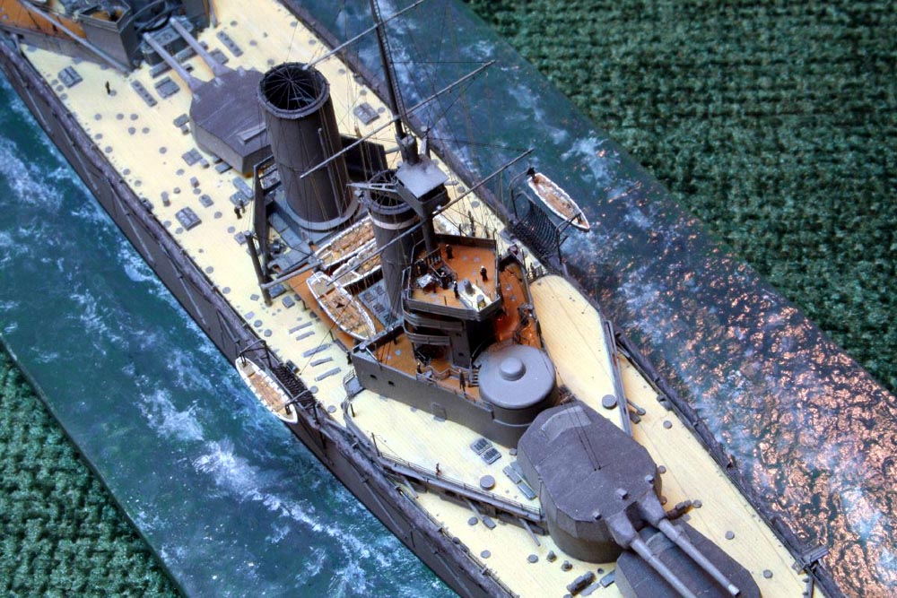
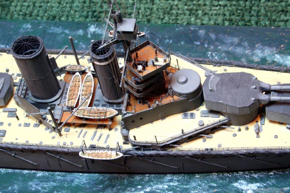
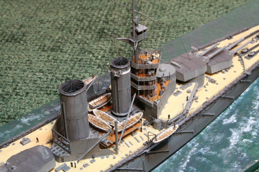
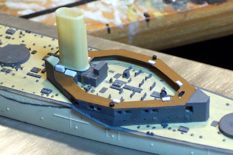
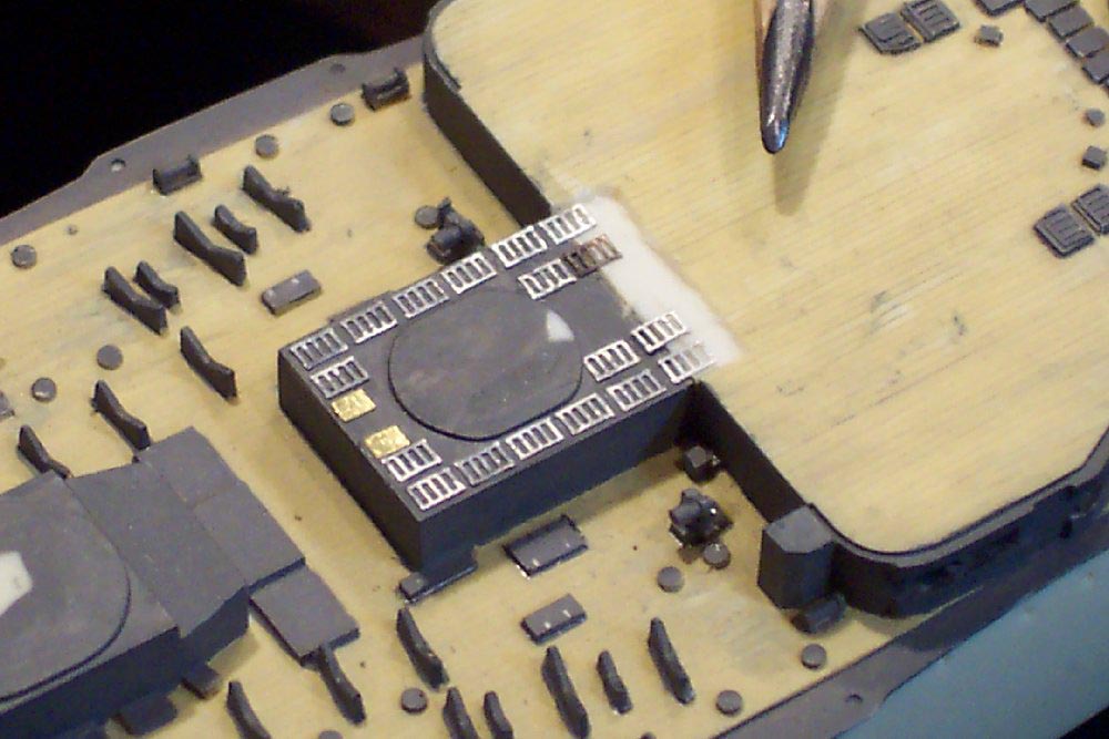
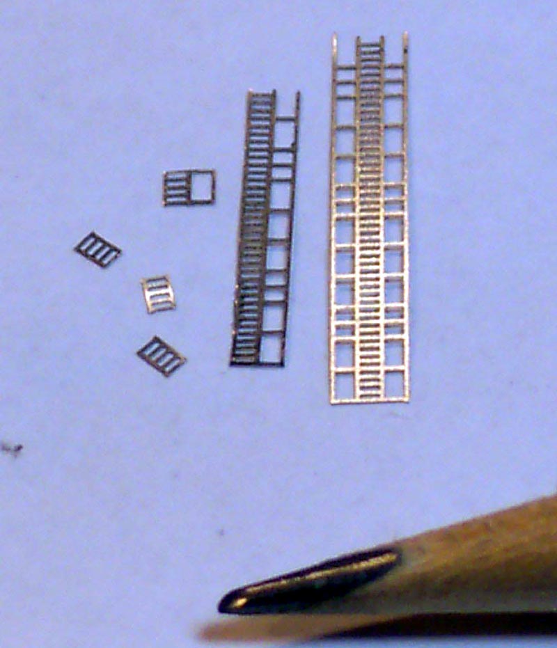
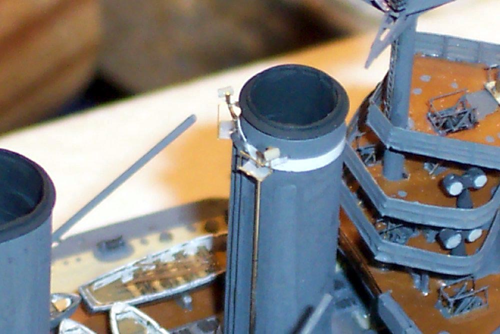
| The funnel bases were somewhat bare-- study of plans and the aforementioned drawings showed them to be festooned with cover plates over vents easily represented with squares of brass/paper I though, further investigation revealed that the cover plates were removed when the vessel was underway... so I now had to simulate the vent grilles... after some experimentation I used old GMM stairs with the handrails trimmed off into suitable sized square vent grilles. Although obviously somewhat overscale, the overall effect is pleasing to the eye on the finished model. | 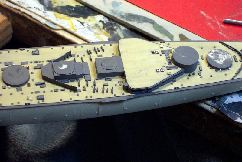 |
|||||||||||||||||||||||||||||||||
 |
||||||||||||||||||||||||||||||||||
 |
||||||||||||||||||||||||||||||||||
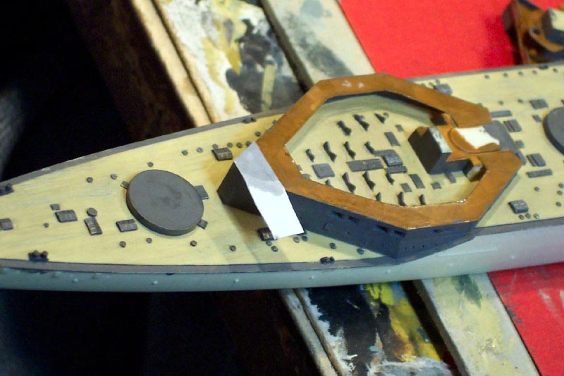
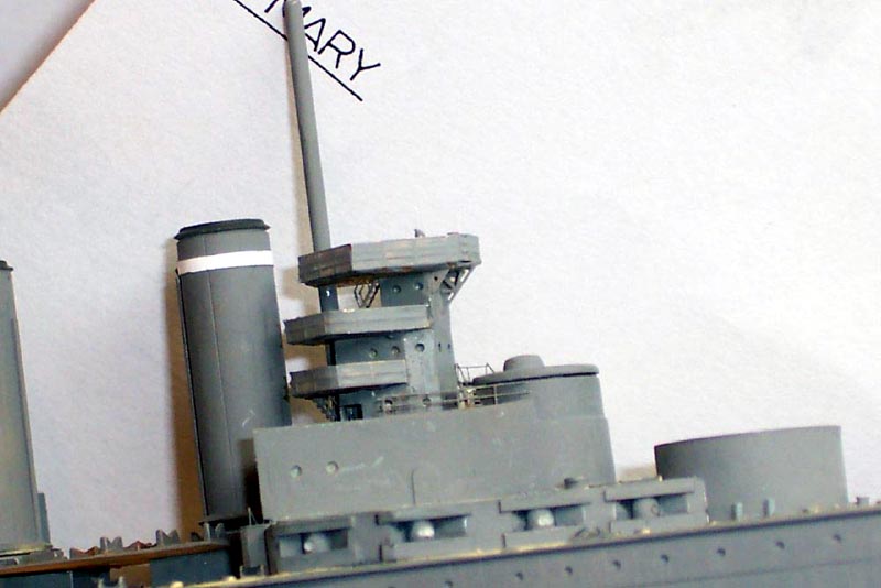
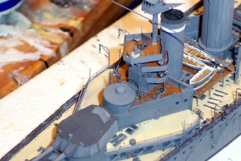
| The first level of the fwd bridge on the real ship was also open aft
and housed some large cable reels etc. The solid casting of the kit was
ground out from underneath and the stairway apertures cut in
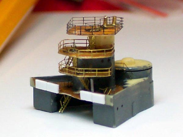
The entire structure turned into quite a project in itself - the cast solid splinter shields were cut away and replaced with PE railing to be filled with White glue to represent the canvas covered railings. All the connecting stairs were installed and when solid the lower mast was drilled true and installed so as to give the structure some stability. The upper bridge had a taller 3-bar railing. I culled this from an old 1/600 GMM Merchant ship fret the difference in scale giving the taller railing effect perfectly! The platform aft of the conning tower was cut from brass and was furnished with railings and stairs. |
 |
|||||||||||||||||||||||||||||||||
| The railings were filled with white glue and the structure placed on the ship- styrene filler plates were inserted to make the aft edge flush with the base according to the photos and plans I had | 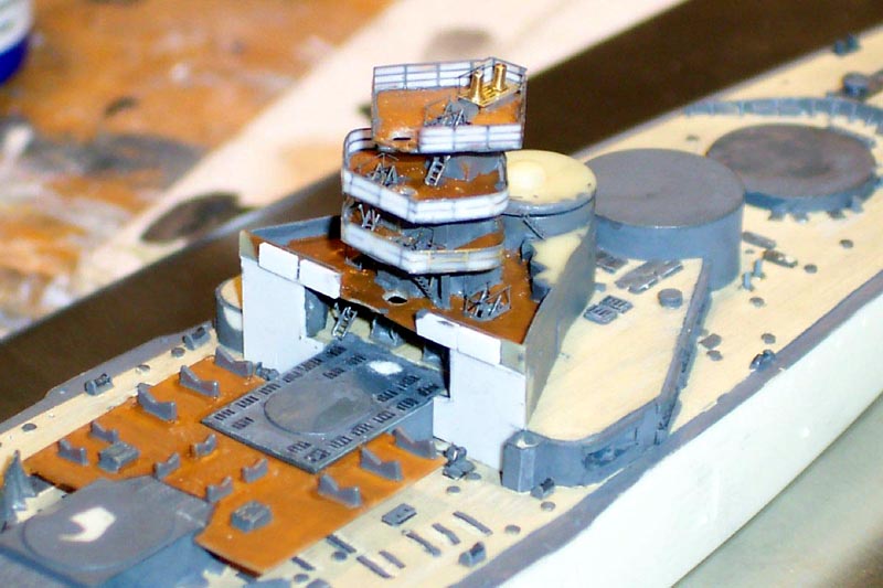 |
|||||||||||||||||||||||||||||||||
| All the cast doors had been carved off and replaced with PE items all over the entire model. The supplied PE blast plates needed a little fettling to get them to sit flush and fair atop the resin bases. | 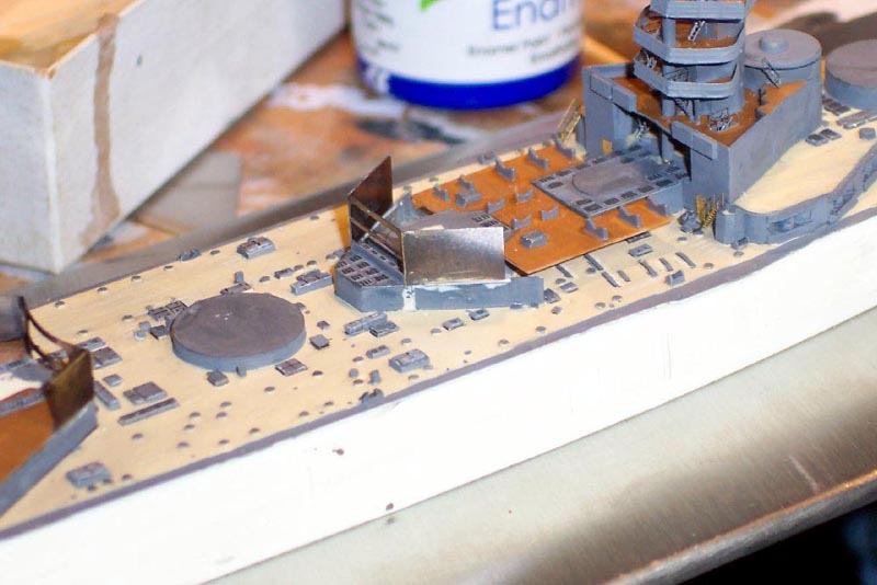 |
|||||||||||||||||||||||||||||||||
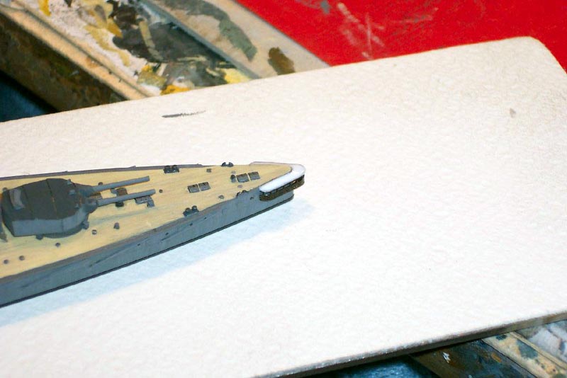
| At this stage the hull was showing signs of slight warpage fore and aft... I nipped this tendency in the bud immediately by affixing the hull to a 3mm stainless steel with stainless steel countersunk screws into pre drilled holes in the underside | 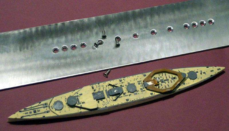 |
|||||||||||||||||||||||||||||||||
| I periodically removed the hull for working on when rotation or access
was required to undersides of platforms but always screwed it back onto
its metal base between work sessions
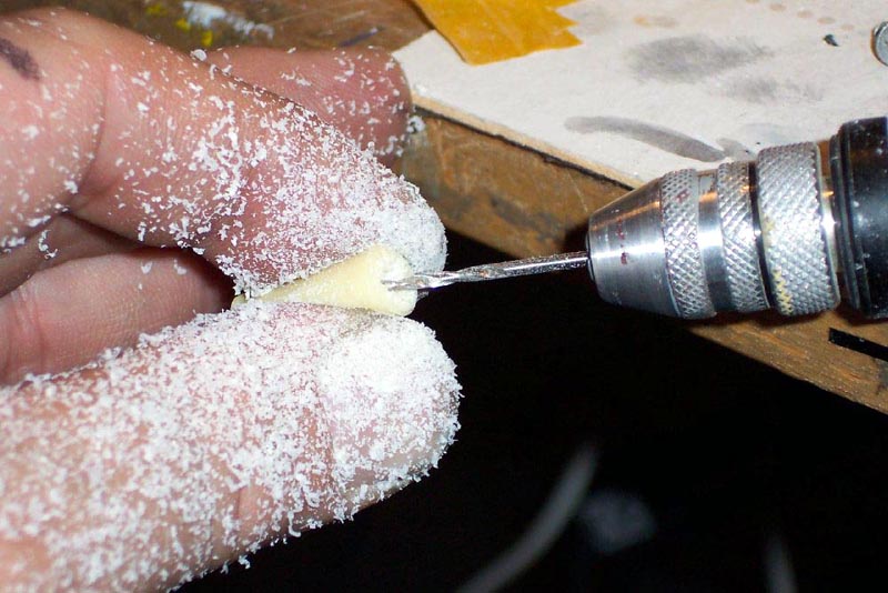
The solid funnels had their centers drilled out, care was needed here to prevent distortion being caused by heat buildup from the cutting tool. |
 |
|||||||||||||||||||||||||||||||||
| Somewhat later I noticed that the fwd funnel was 1 millimeter too short
in relation to the others. I would otherwise have made a replacement item
. As the funnel base was surrounded by boats I cured the problem by inserting
a sliver of styrene underneath the funnel flange is a little higher but
cannot be seen due to surrounding boats ..
The complex and delicate funnel caps were made entirely of stretched sprue With the bridge installed and the mast inserted all the way through into the lower hull my attention turned to the supporting struts and gussets under the upper bridge level with paper and cannibalized PE scrap giving the desired effect. |
 |
|||||||||||||||||||||||||||||||||
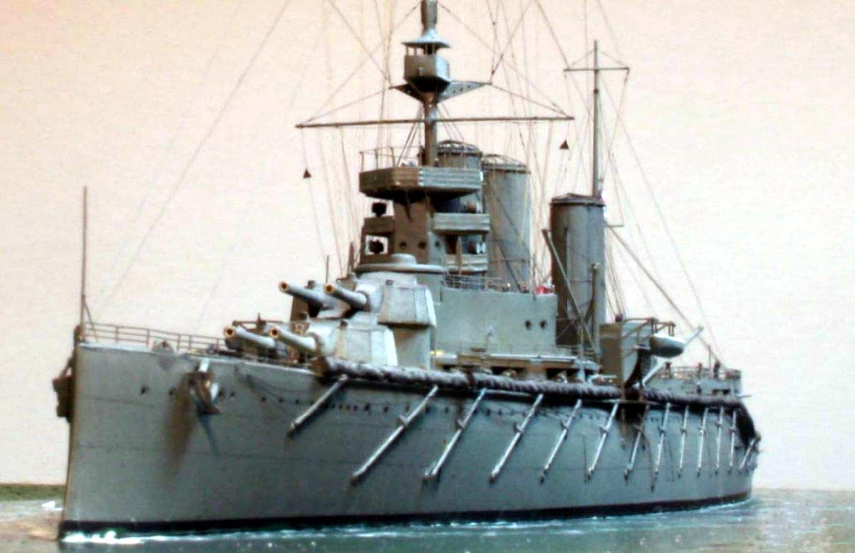
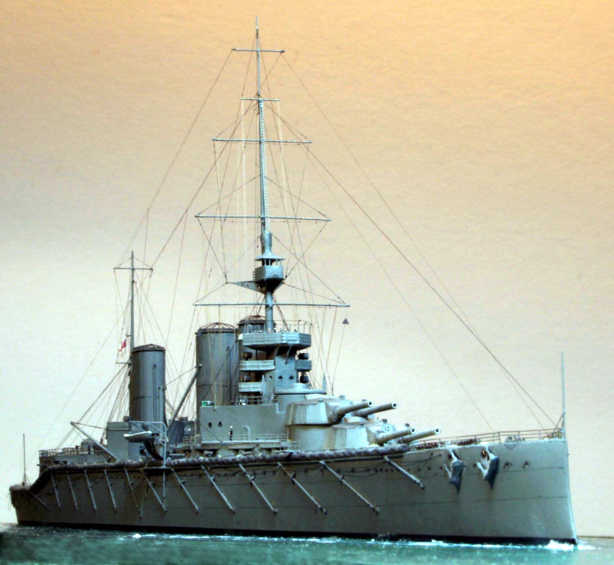
| With the hull topsides painted the ship was beginning to look very elegant, but inspite of NNT having captured the slight tumble home of the hull sides very well it all looked a little ' flat'. I drew in all the rigoles( eyebrows) for the scuttles with a sharp pencil . Detailed examination of photos of the real ship showed that in most lighting conditions the fore and aft hull plating strake lines were visible. Reckoning it being impossible to recreate these within scale I opted to 'sketch' in this detail. Having applied Tamiya Masking tape following the layout on the plans I then drew along the tape guide with a very sharp pencil. After removal of the tape the effect was made more subtle by brushing down vertically with mentholated spirits which coincidentally removed the sheen of the pencil rather well as a bonus | 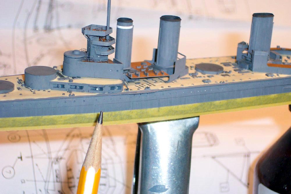 |
|||||||||||||||||||||||||||||||||
| The somewhat plain aft rangefinder had observation slits painted on and a brass cross member installed after drilling the top of the small casting athwartship | 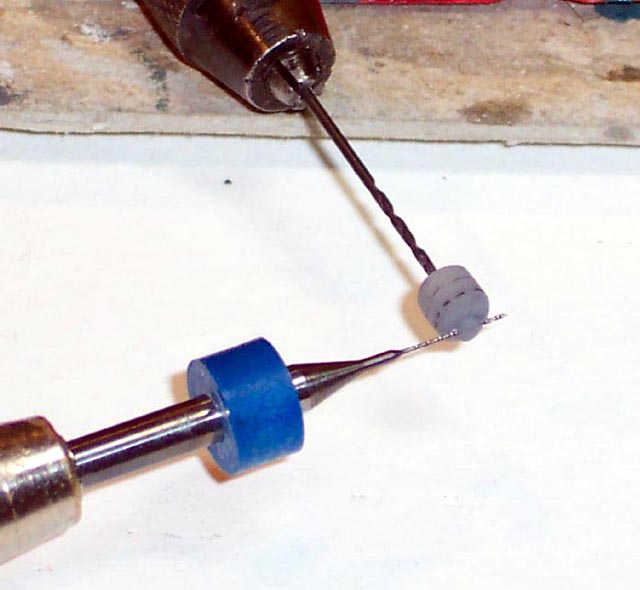 |
|||||||||||||||||||||||||||||||||
| The well rendered turrets had integral blast bags nicely shaped-finding no reason to re-invent the wheel I simply drilled out the resin and installed the NNT supplied Schatton gun barrels. | 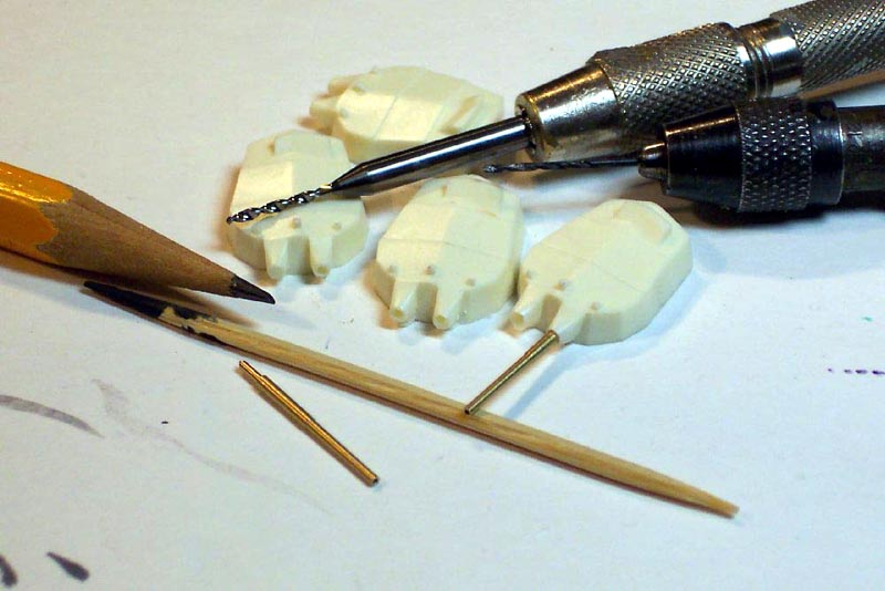 |
|||||||||||||||||||||||||||||||||
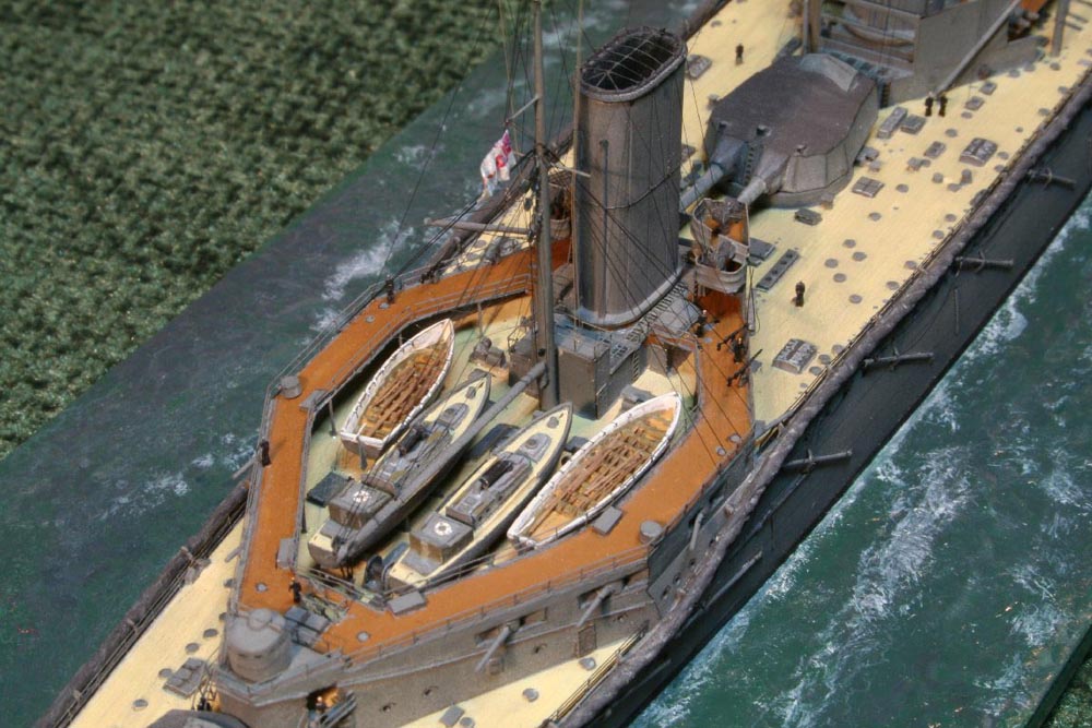
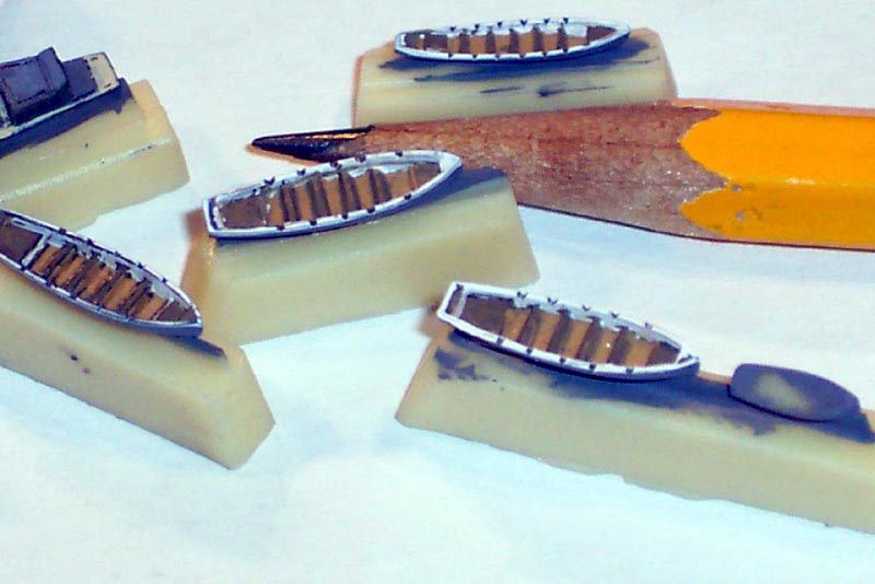
| The ships boats impressed with their outline accuracy small details such as handrails, folded stack, doors cleats and life preserver were added to the steam launches whilst the oar propelled boats had the sculling notches cut in using a blade | 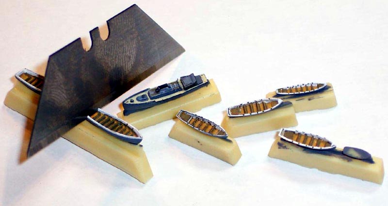 |
|||||||||||||||||||||||||||||||||
 |
||||||||||||||||||||||||||||||||||
| The aft sternwalk was made using the excellent supplied PE mesh piece in conjunction with a paper floor and a paper roof which was given its conical shape using white glue | 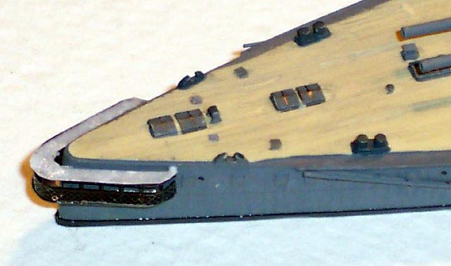 |
|||||||||||||||||||||||||||||||||
 |
||||||||||||||||||||||||||||||||||
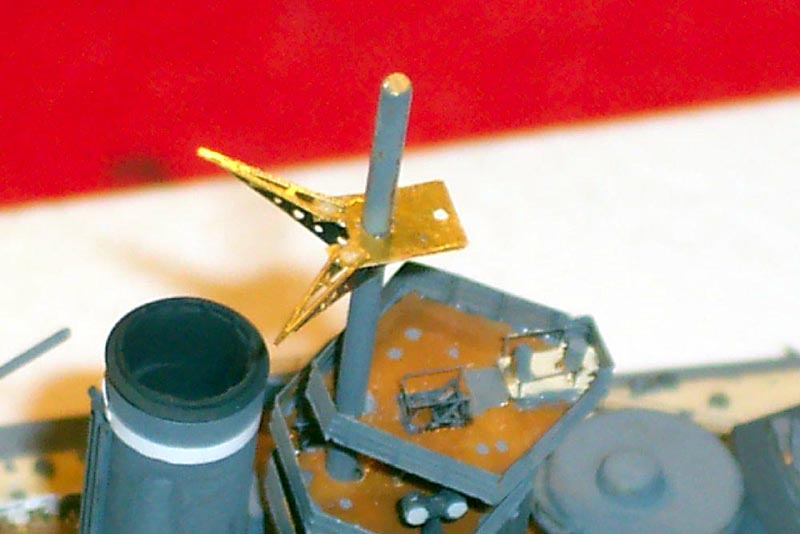
| The Starfish platform on the fwd mast was supplied as a solid resin casting- good outline but too clunky for my liking so I made a new platform of cannibalized WEM PE and paper | 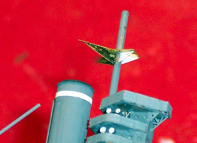 |
|||||||||||||||||||||||||||||||||
 |
||||||||||||||||||||||||||||||||||
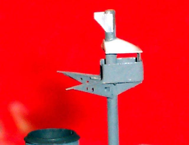
| The open spotting top was supplied as a solid casting fine
for when the ship was in harbor as the apertures were covered with canvas
screens- however with the model representing a vessel underway I made a
new platform of paper and a white glue roof
Siren platforms on the fwd funnel were made of paper with pipes and sirens being of brass wire |
 |
|||||||||||||||||||||||||||||||||
 |
||||||||||||||||||||||||||||||||||
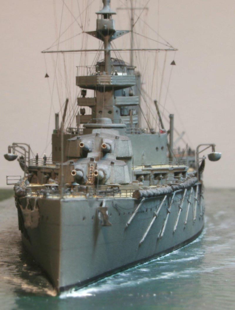
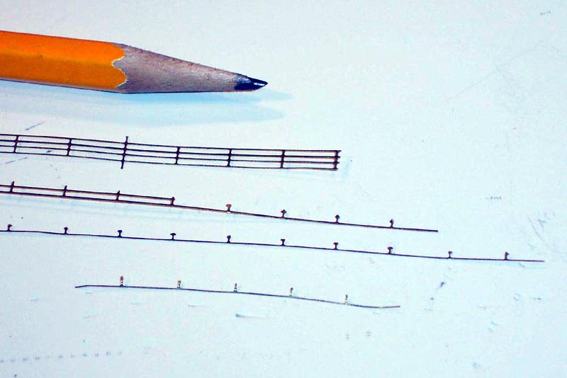
| After installing the nickel silver wire torpedo net booms . These had
brackets that held them in place on the hull side which appeared to have
a locking bar that went over the boom in some way I mimicked the photos
I had and made these from RC Cammett vinyl tape secured with a micro drop
of CA at both ends a sharp result I was pleased with!
I wanted to install the brailing davits for the net. The main feature was perfectly regular spacing and consistent size difficult aims to achieve perfectly the slightest error in distance/inclination or size would be worse than not having them at all. I cut up old and overscale 1/350 handrails, using the railing joint ' ball' as the pulley block when bent around by 90 degrees it gave a fair impression of the item but more importantly to me was totally repeatable in size and spacing! |
 |
|||||||||||||||||||||||||||||||||
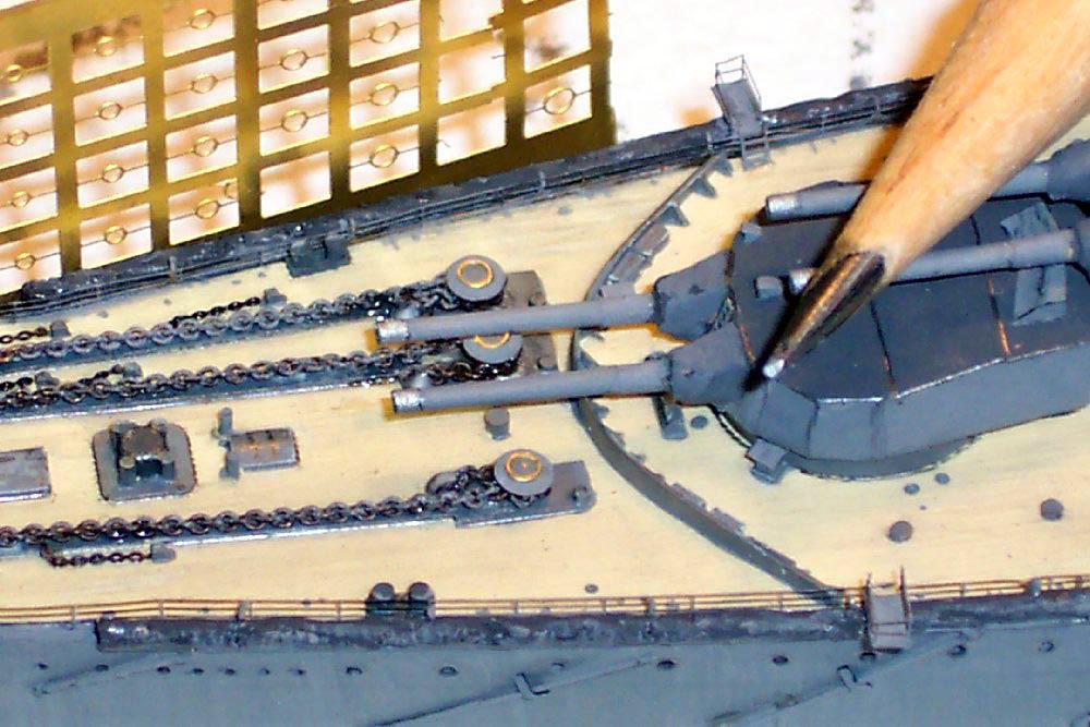
| Torpedo nets were supplied with the kit, however after study of photos
I felt that the supplied cord was too thick and regular in appearance so
I used a button cord partially unraveled, then soaked in CA and then painted
with PVA the overall effect is quite pleasing
The anchor chain was a Model Railway item, passing through the drilled hawse pipes to the fine kit supplied PE anchors with the capstans being made of N-scale brass buffers topped with some fine PE brass circles from L'Arsenal. The check chains were made of some old WEM PE chain |
 |
|||||||||||||||||||||||||||||||||
|
On the upper bridge platform I added the awning stanchions as well as the portside small chart table( complete with tiny paper chart!!) |
 |
|||||||||||||||||||||||||||||||||
|
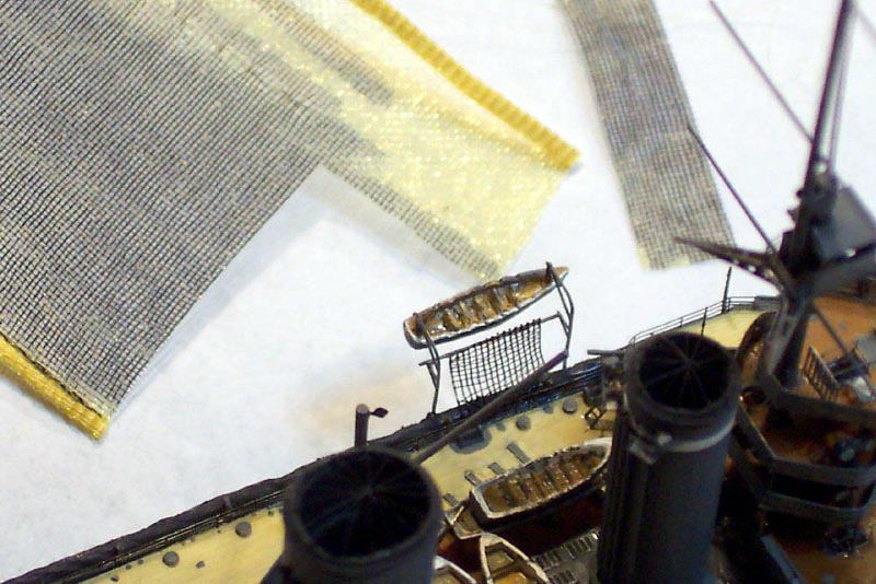
The kit supplied PE sea boat davits featured the griping spar brackets, nice touch, so were used in conjunction with a boarding net cut from cake decorator's yellow veil colored with an indelible marker pen. |
 |
|||||||||||||||||||||||||||||||||
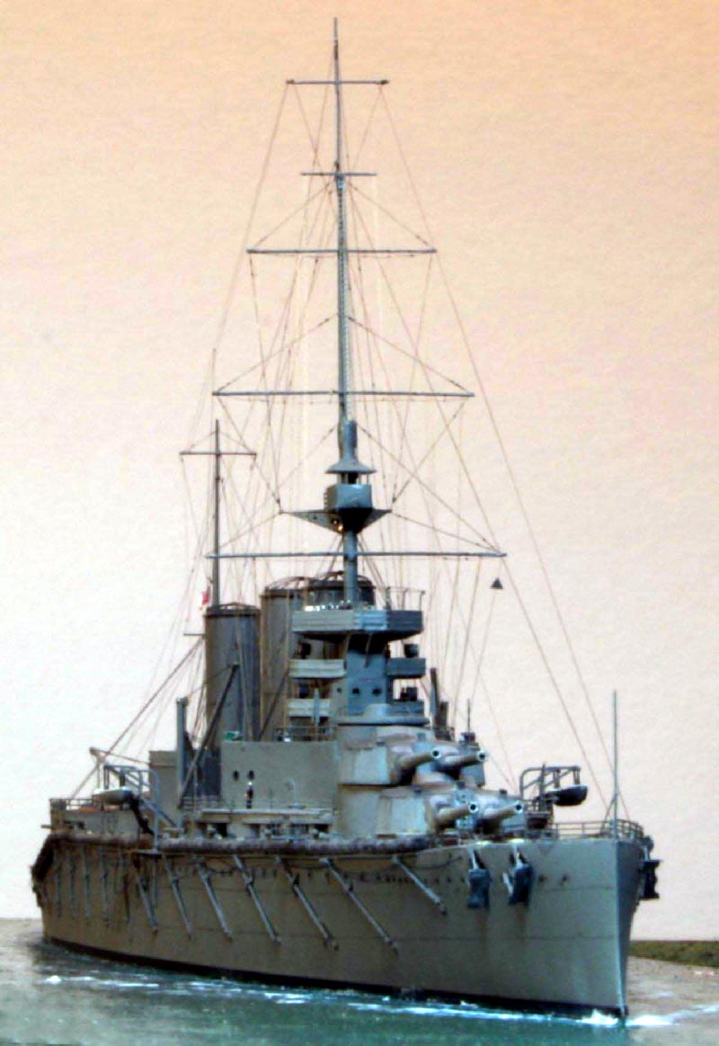
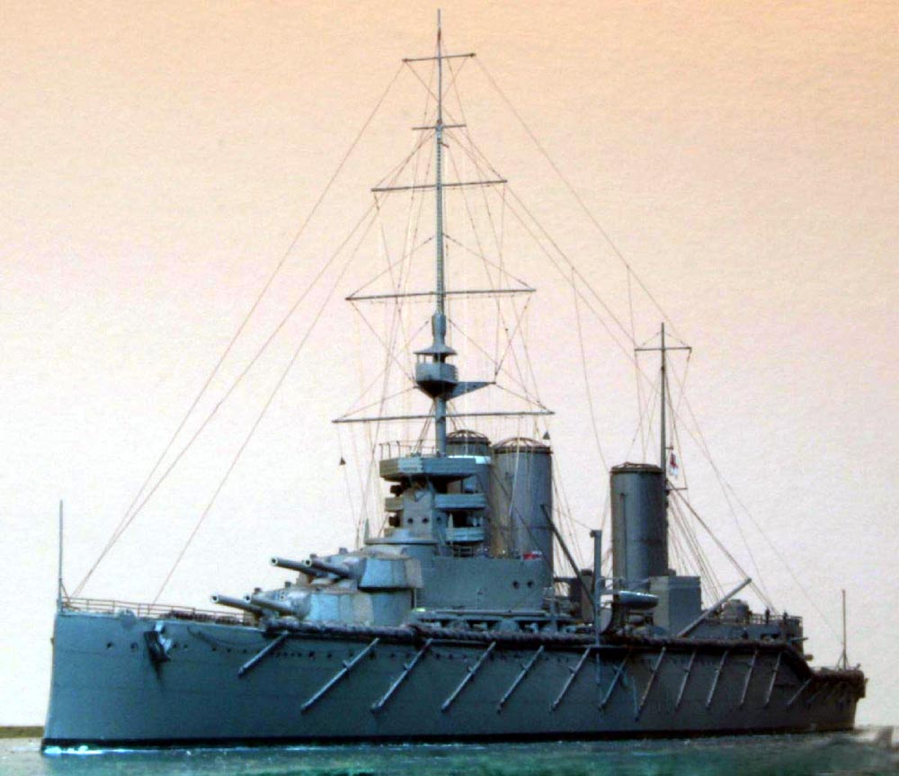
| The model had a GMM PE crew installed , and was ready for flat coat
and rigging.
I spent much time attempting to create passable cage ariels, they are always drawn as being very prominent on plans, yet in contemporary photos they are often nigh invisible. Even using GMM Gold plus rails rolled around thin wire the overall effect was far too heavy for my liking |
 |
|||||||||||||||||||||||||||||||||
| I elected to leave them off and indicate them on the model by using extremely fine stretched sprue in their positions. All the masts were made of stainless steel welding rod that had been tapered for me by Steve Foulkes using a drill and counter-rotating sanding disc in an angle grinder... All rigging was stretched sprue tightened in the usual manner with hot smoke from incense sticks and no mean amount of patience! Handrails were GMM Gold plus superfine in the main and the entire model apart from the decks was painted with WEM Colourcoats-- washed with white watercolor to reduce their ' strength' a bit. | ||||||||||||||||||||||||||||||||||
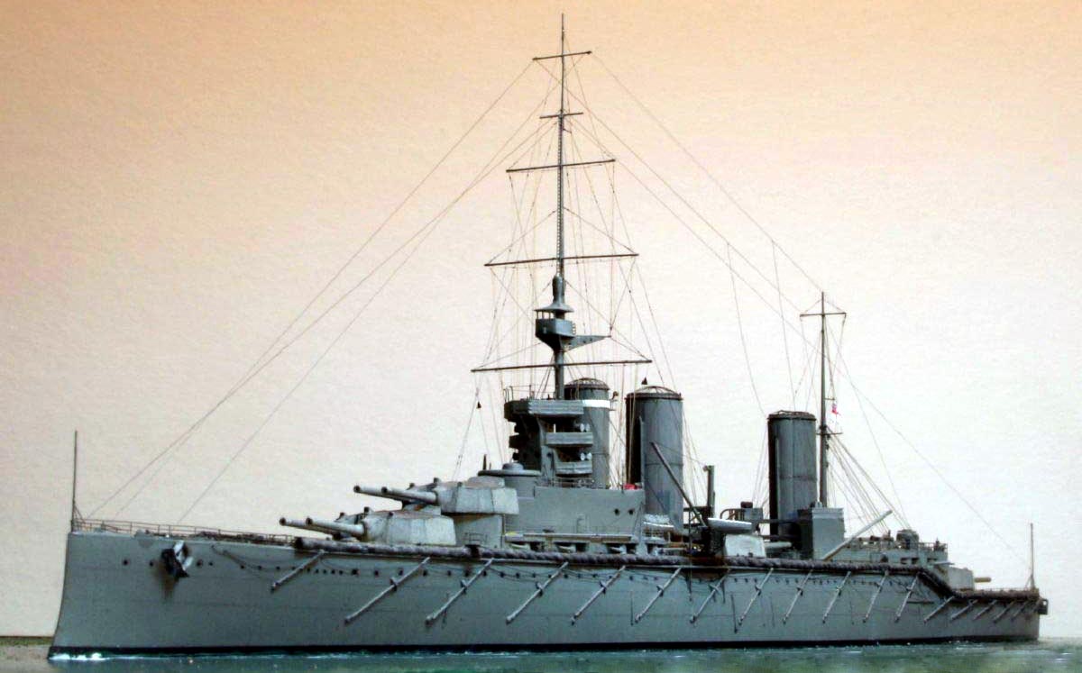
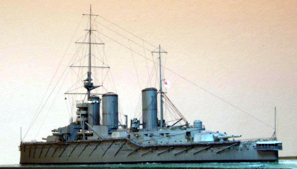
Having not a single photo of HMS Queen Mary at speed I
elected to portray her trickling along at about 8 knots or so!
NNT has filled a void in the available ship subjects with a great kit, which would build into a fine replica out of the box, but can be much further refined if so desired. My primary source of information was the aforementioned Robert's plan and book along with:
|
||||||||||||||||||||||||||||||||||
| Useful web resources: |  |
|||||||||||||||||||||||||||||||||
![]()
© ModelWarships.com