|
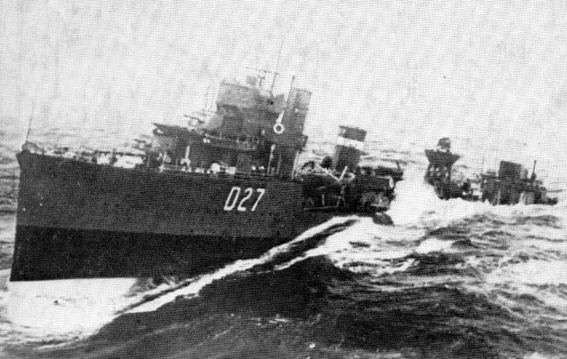
At the beginning of World war One Royal Navy destroyer design had evolved into a general configuration that would remain essentially unchanged until the 1960s. The M class were ordered in 1913/14 - as an improvement on the preceding L class having an additional 6 knots added to the top speed at the insistence of the then First Sea Lord of the Admiralty Winston Churchill. The class numbered 13 vessels-all of which varied slightly in machinery configuration as well as dimensions dependent on where they were built! Fundamentally a successful design the order was repeated for another 87 boats including some 11 specials .even among the standard boats there were some significant visual differences , various machinery installations- two or three shafts; geared and non geared turbines which resulted in differing stem and stern shapes. On all the vessels the Stem was double thickness casting to facilitate the ramming of U-boats if the opportunity presented itself. Overall a successful design, but as the hulls were not galvanized to allow for a quicker combined with their arduous service they were worn out at the end of the war; few survived the mass scrapping of 1921 With war imminent, speed of delivery of these vessels was of great importance, with Mary Rose being launched on 08 October 1915, whereupon she joined the Grand Fleet the following year. She was present at the Battle of Jutland and continued on with Grand Fleet service until October 1917. Thereafter she and another destroyer HMS Strongbow, were escorting a Scandinavian convoy in the North Sea and were intercepted by two German light cruisers, SMS Brummer and SMS Bremse. Despite being seriously outgunned the two destroyers turned to attack their enemy, but the odds were heavily against them and Strongbow was put out of action by the first German salvo, sinking three hours later. With a gunnery duel appearing hopeless Mary Rose tried to get into position for a torpedo attack, but the German gunnery proved to be devastatingly accurate and she was sunk by gunfire before being able to fire her torpedoes. The unprotected convoy was now at the mercy of the cruisers who proceeded to sink nine of the twelve ships
|
|||||||||||||||||||||||||||||||
| Building the model | |||||||||||||||||||||||||||||||
|
was happily a pretty straightforward procedure!
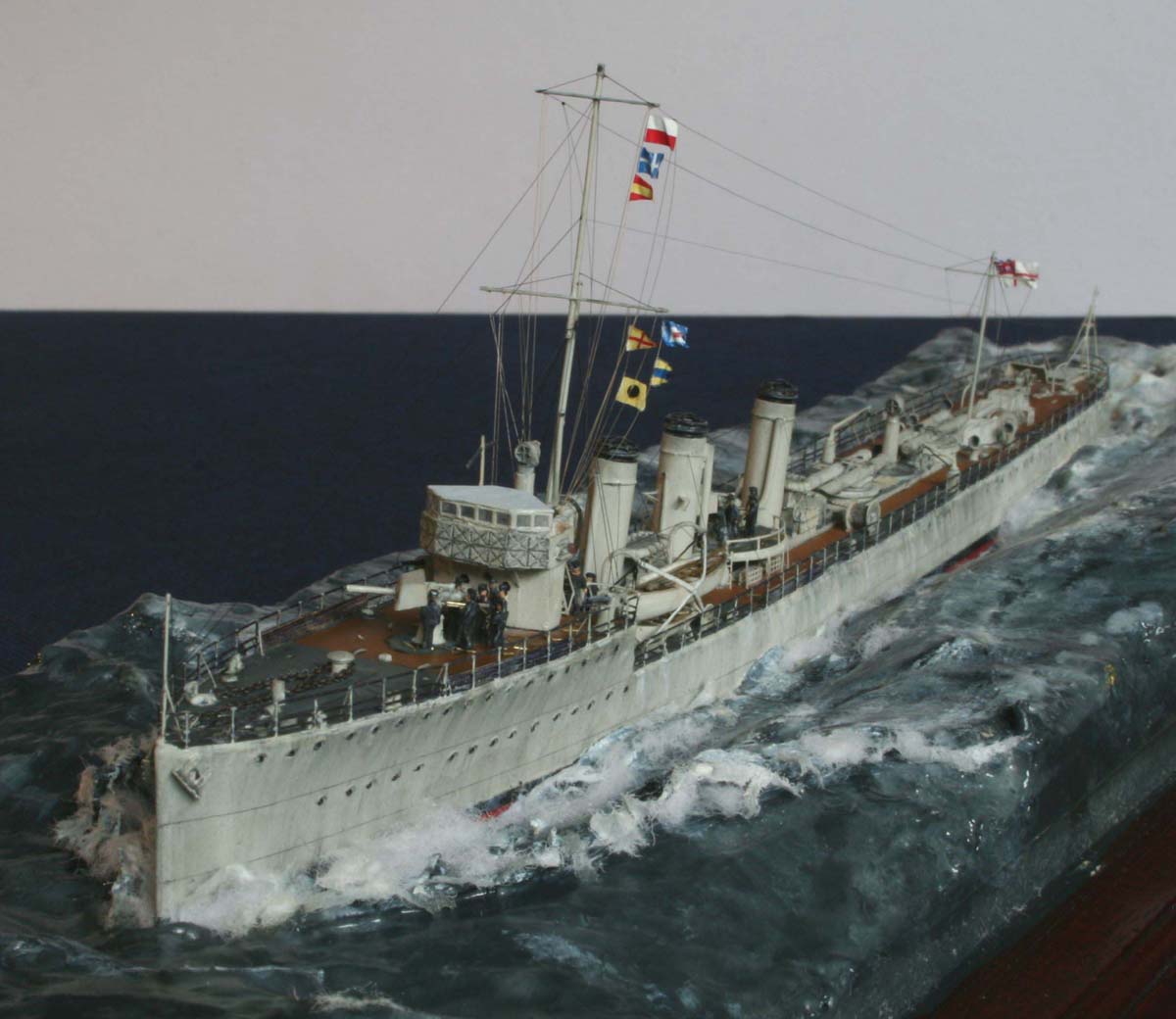
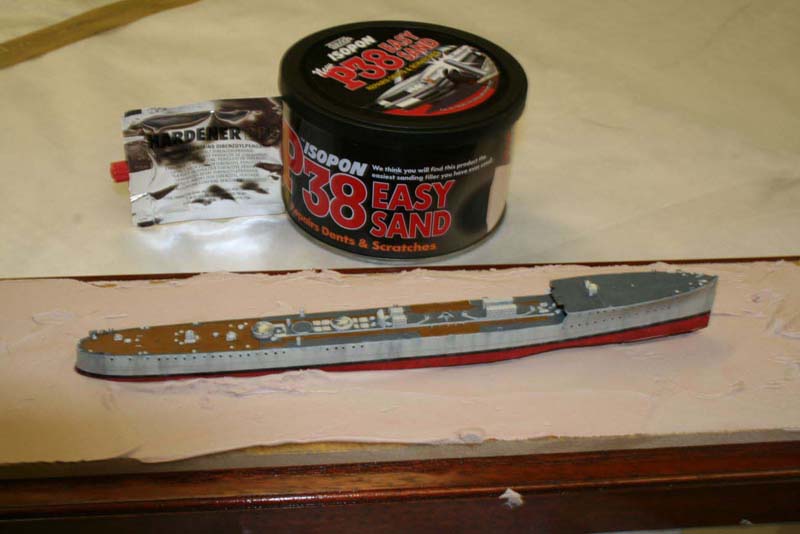
Released around 1999, this White Ensign Models resin kit is now of the older resin generation. The kit I built is from the last-ever production run. Nevertheless the casting was sharp and the original mastering crisp. The kit was designed with a split hull allowing waterline and full-hull options. Although I wished to portray the ship afloat; having decided at the outset that I wanted my Mary Rose to show some lower hull in a long rolling swell-the inspiration coming from the front cover of the Anthony Preston Book V & W class destroyers. |
click images
to enlarge |
||||||||||||||||||||||||||||||
 |
|||||||||||||||||||||||||||||||
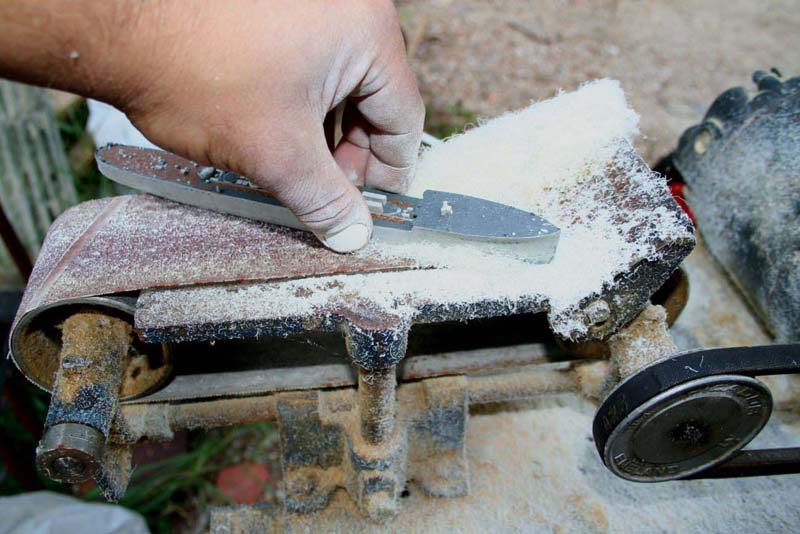
| This was the first time I had ever joined an upper and lower resin hull-I was delighted with the excellent fit requiring virtually no filler and only a slight paring away of the lower hull at the stern. The completed hull was then ground away in the appropriate areas using my belt sander so that the total height above the baseboard was not excessive. | 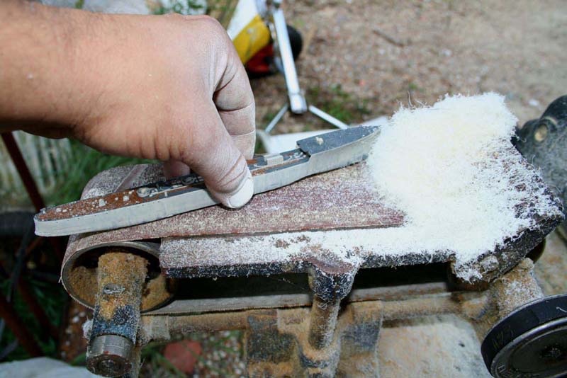 |
||||||||||||||||||||||||||||||
 |
|||||||||||||||||||||||||||||||
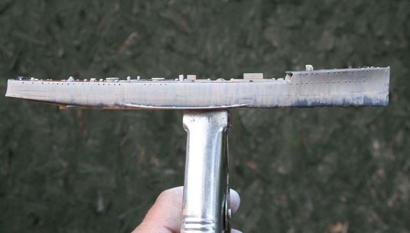
| Even in 1/350 the ship is only 9 ½ inches length
over all, so I was careful to not overawe the ship with the sea height.
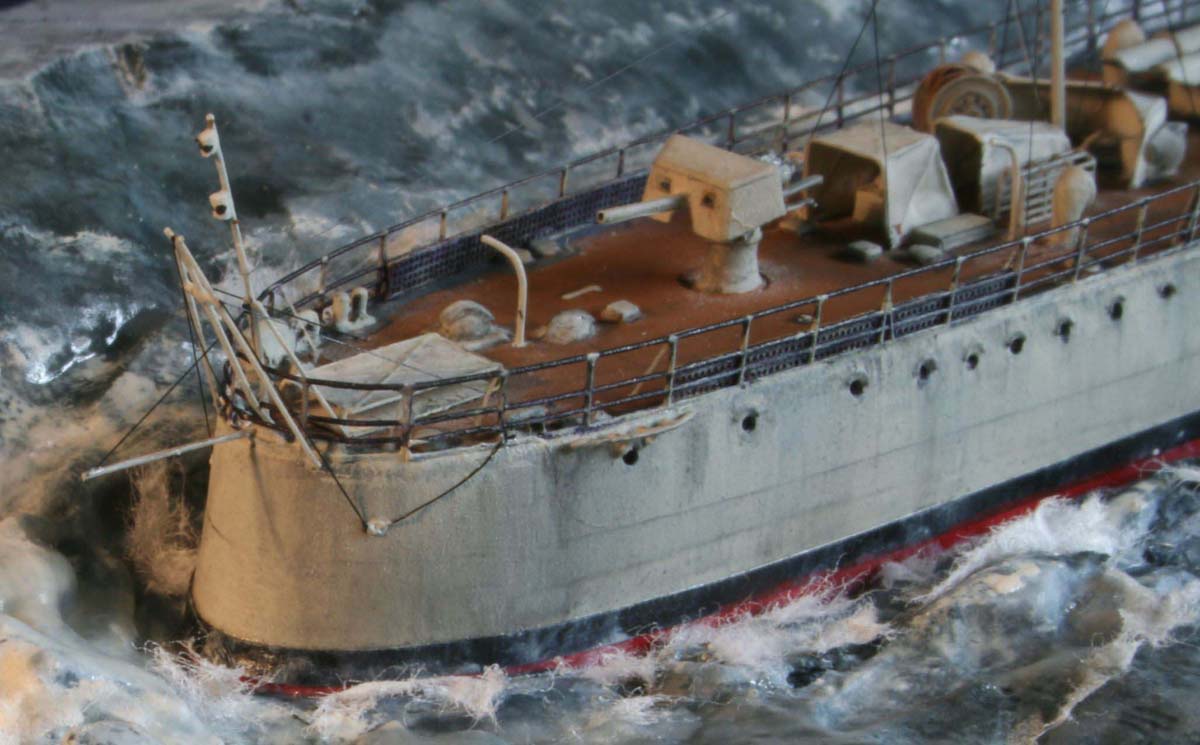
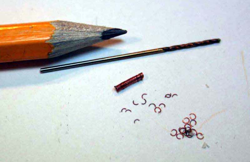
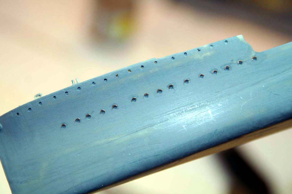
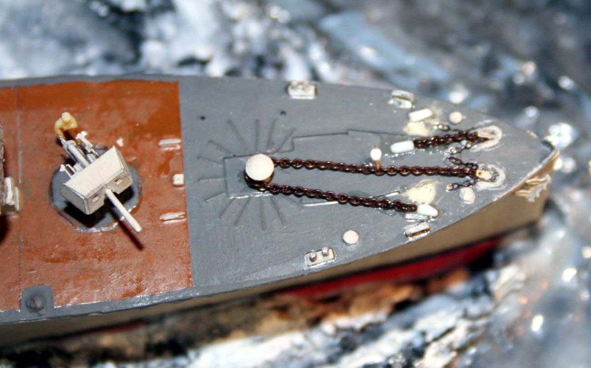
After the first couple of coats of paint the hull appeared to my eyes a little flat and featureless; upon closer examination of photos of M class ships showed visible plating runs as well as eyebrows( rigoles) above the portholes. The eyebrows were fashioned from very thin copper wire, these were made by wrapping the wire around a suitable drill shank to create a spring, cut longitudinally and the cut again on the bench, after careful selection they are attached to the hull using clear matt varnish. The waterline was marked using the faintly visible join as a guide. I did not feel that applying the plating strakes as separate layers was likely to look in-scale so I elected to imply their presence by using a thin pencil line run along a strip of Tamiya masking tape; the plating lines were then brushed across vertically with powdered graphite dust ( pencil on 1200 grit) using Methylated spirits as the carrier-so as not to disturb the underlying enamel paint. |
 |
||||||||||||||||||||||||||||||
 |
|||||||||||||||||||||||||||||||
 |
|||||||||||||||||||||||||||||||
| After painting the underside red the black boot-top was applied using
my usual method of vinyl matt RC Cammett tape this avoided any potential
tears with masking tape on a weathered and completed hull.
The upper decks on these vessels were covered in Cortisone over steel decks, the strips of Cortisone were not defined along the edges on the casting- I decided to achieve crisp edges by using the vinyl tape again cut into the appropriate sizes and shapes. |
|||||||||||||||||||||||||||||||
| Were the Cortisone was cut around bollards and deck fittings
etc. I drew a line with a pencil to act as a barrier to the paint.
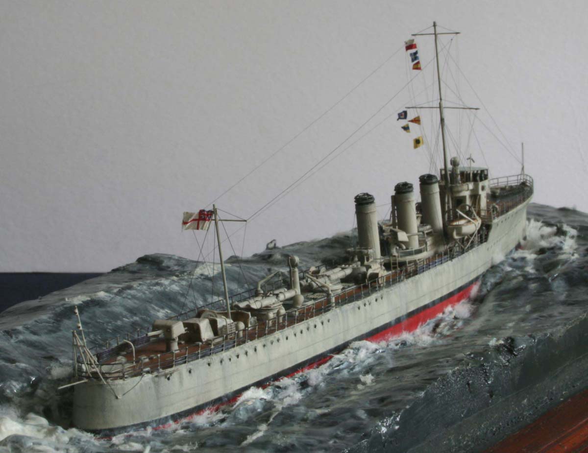
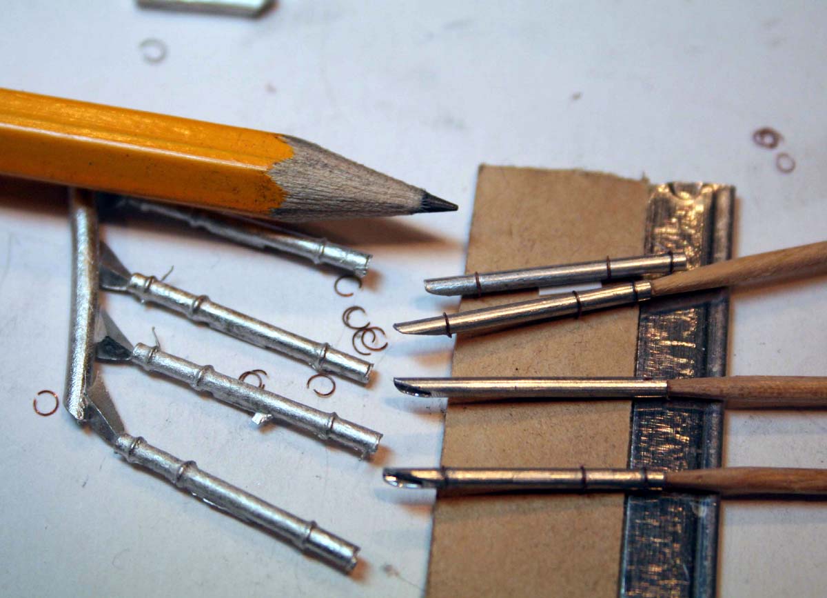
The kits torpedo tubes were cast in white metal; these however were not sharp enough for my liking so I elected to make replacements using aluminum tubes with copper wire. The end result justified the effort |
 |
||||||||||||||||||||||||||||||
 |
|||||||||||||||||||||||||||||||
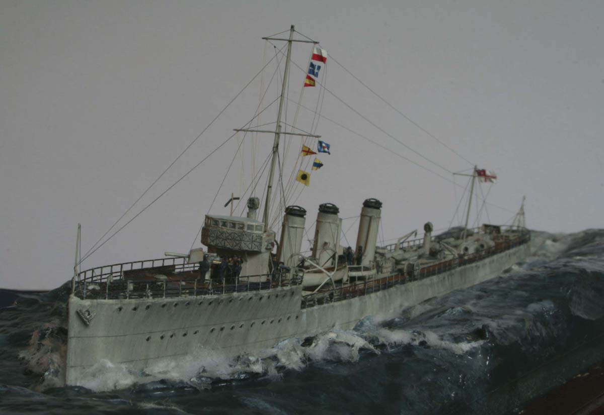
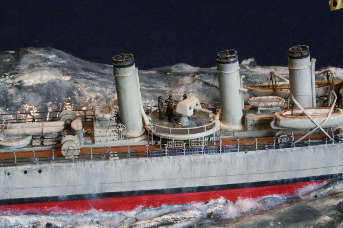
| The funnels in my kit were made of resin- one of the funnels had very slight waisting. In retrospect this would have been virtually invisible alas I decided to manufacture new funnels using brass tubes, copper wire and small stainless steel washers with the steam pipes being made of soft tubing to allow for the curves to bypass the midships 4 gun band-stand. | 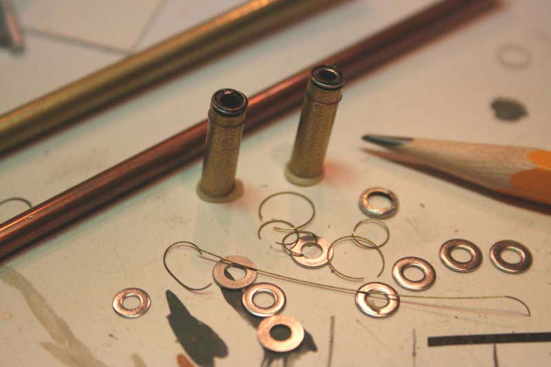 |
||||||||||||||||||||||||||||||
| I added some of the fine PE details from the fret to the deck structures. I was particularly pleased with the boiler-room vent covers-these after painting were gently smudged with a pencil dust finger, which nicely accentuated the relief etching of the hinges etc. | 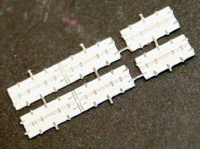 |
||||||||||||||||||||||||||||||
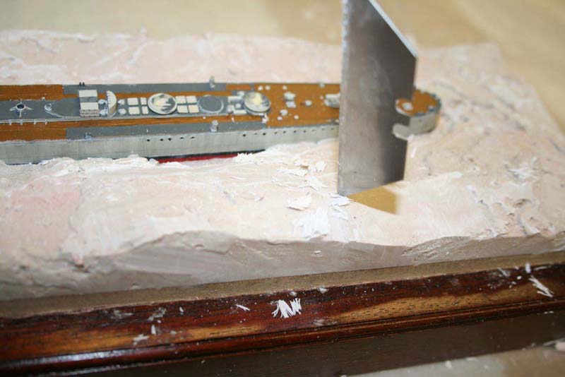
| With a gulp of air and some Dutch courage I then proceeded
to mount the ship in its swell of very rapid setting Auto-bodyfiller ,
this has a workable window of around 3-5 minutes..! but it does have the
advantage that a created wave shape will not droop until setI wanted the
ship to be set within the surging waves not merely placed on top.
After a few repeat applications of filler the base and ship were set aside to cure this is an exothermic reaction the heat production was surprising! Once fully cured I set about carving any granular appearing structures away using sharp blades. |
 |
||||||||||||||||||||||||||||||
 |
|||||||||||||||||||||||||||||||
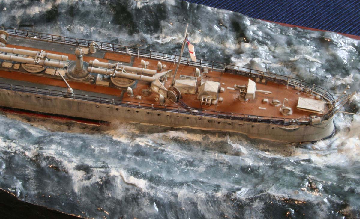
| The sea was then given a coating of white glue to smooth out any
depressions, after which the long process of painting took place in a variety
of colors, the foam streaks were mixed and blended, washed and highlighted
numerous times until I was happy that it resembled the storm tossed North
Sea that I crossed (on a big and safe Ferry!) 20 years ago from Harwich
to Hamburg!!
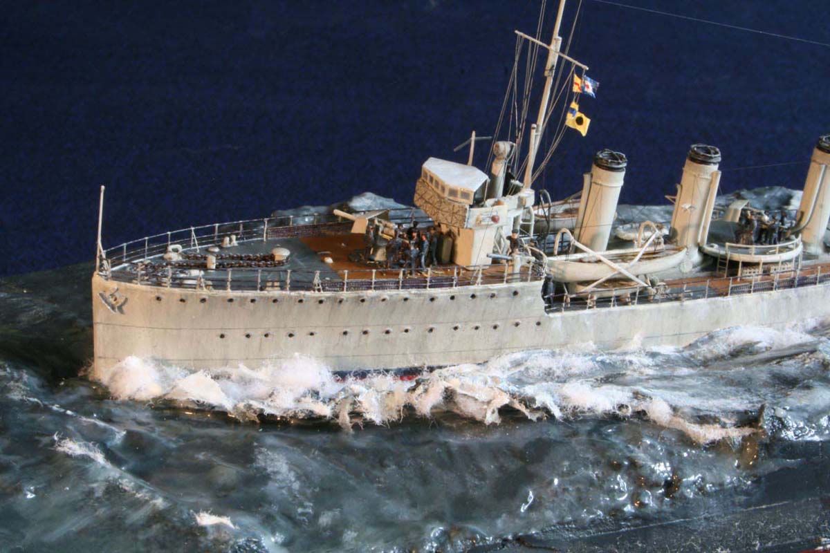
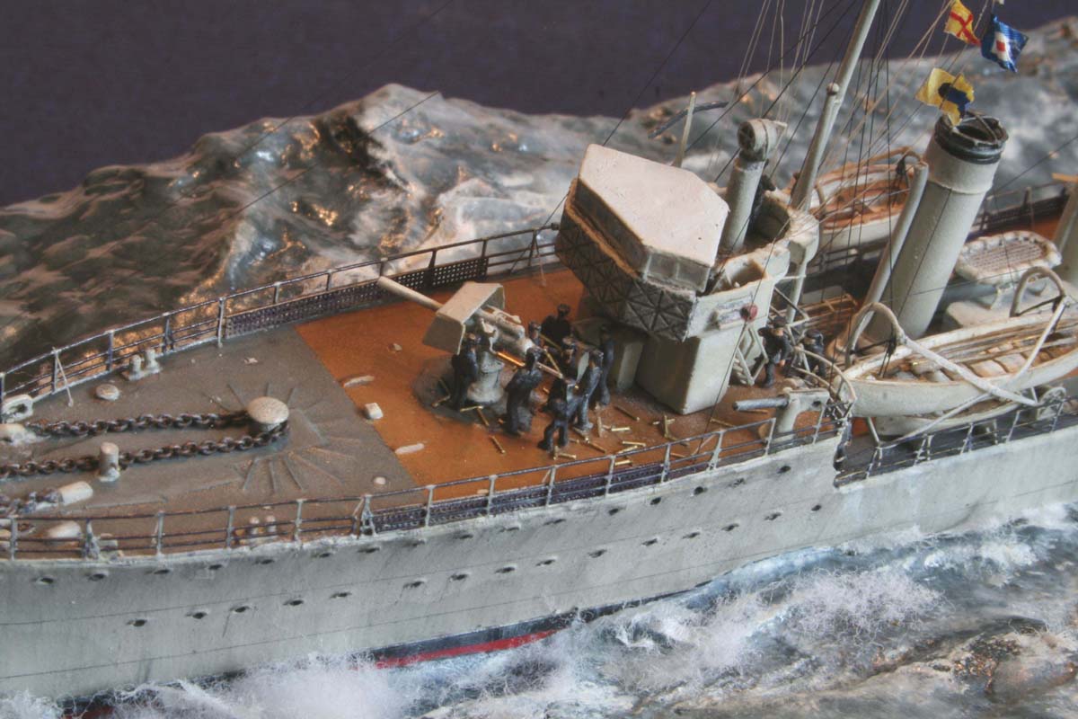
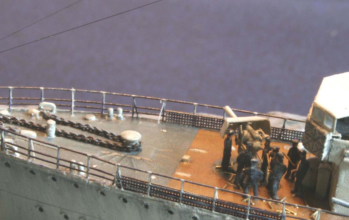
The remaining construction proceeded in a predictable fashion the detailed instructions being followed in conjunction with the 1/192 Sambrook plan along with a plethora of photos that were scanned for me from a variety of rare books! The Foredeck area was altered with a new capstan made of brass tube and an N-scale Model Railway Buffer , Sampson post and new anchor chain hawse-pipes-the kit layout did not allow for the check-chains. |
 |
||||||||||||||||||||||||||||||
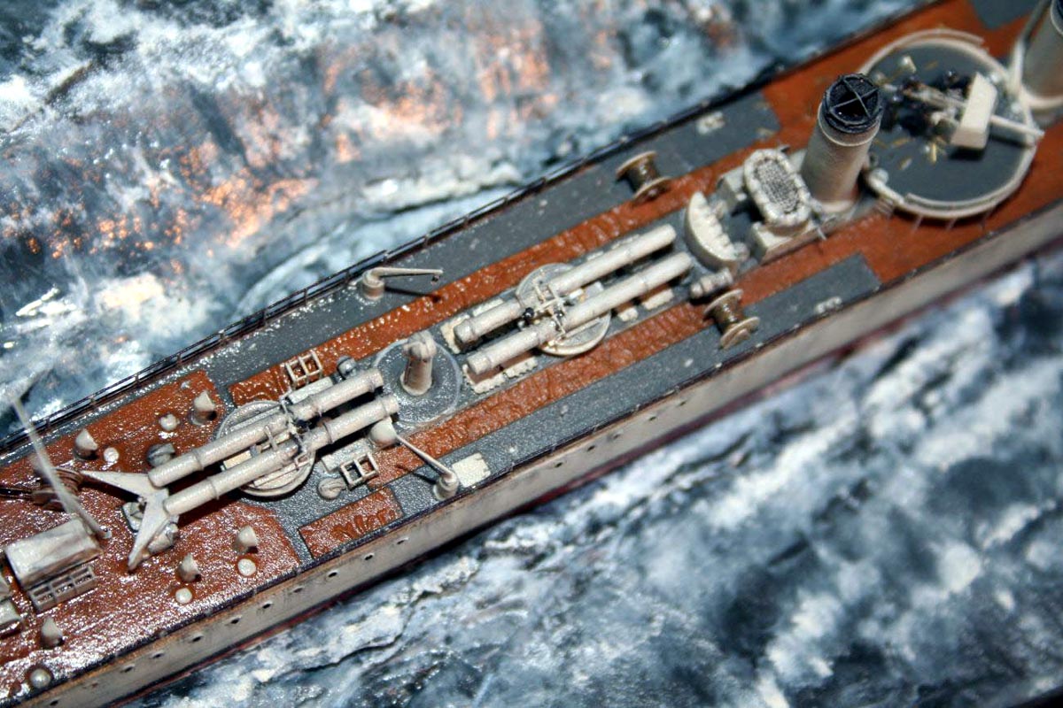
| The cast cable reels looked a bit small according to the Sambrook plan-I made some replacements using the GMM PE reel sides the drums were wrapped in copper wire. The bandstand for the midships 4 gun had support around the edges added using light gray stretched sprue this was glued on at the base until perfectly vertical; then attached at the top using polystyrene liquid cement, once set the waste was simply melted off using more poly cement. | 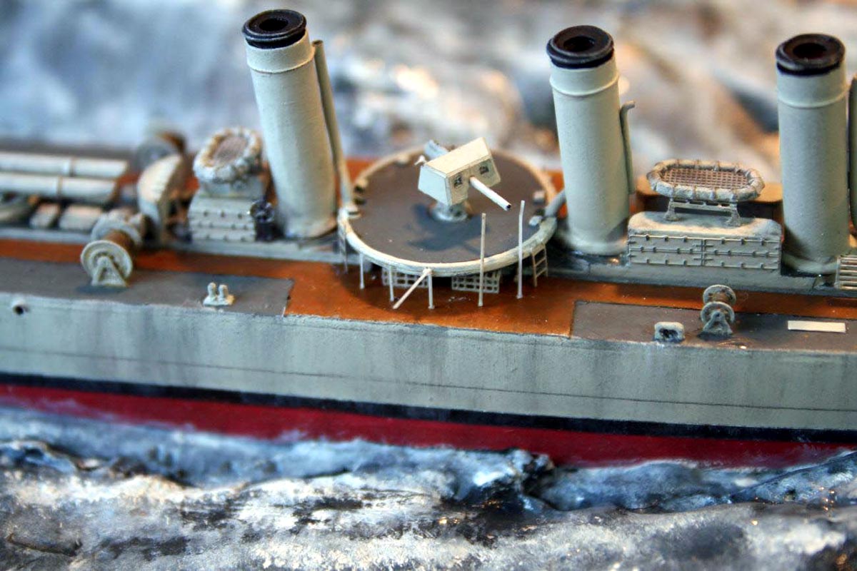 |
||||||||||||||||||||||||||||||
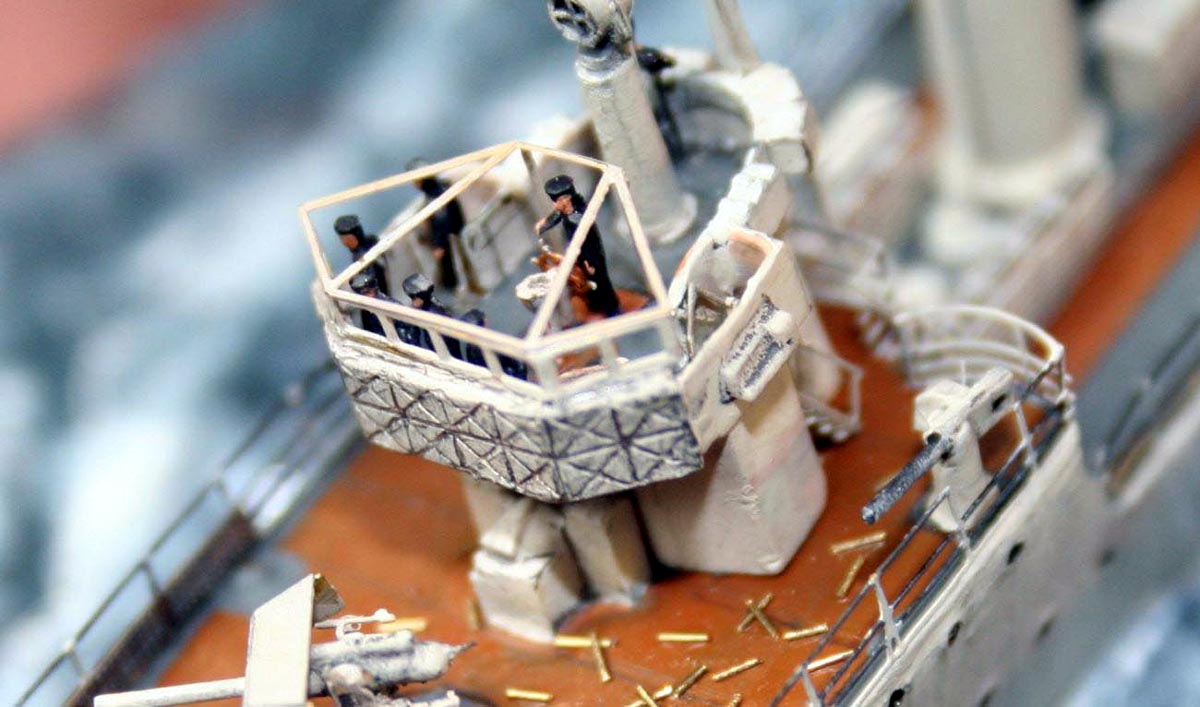
| The bridge was detailed with chart table, binnacle and wheel, officers and a rating at the helm (using the excellent resin 3-D figures from LArsenal) | 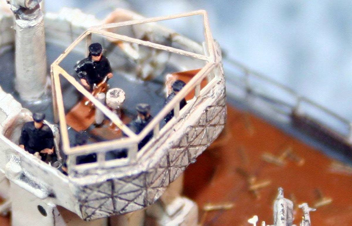 |
||||||||||||||||||||||||||||||
 |
|||||||||||||||||||||||||||||||
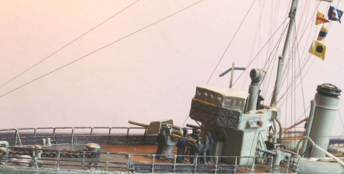
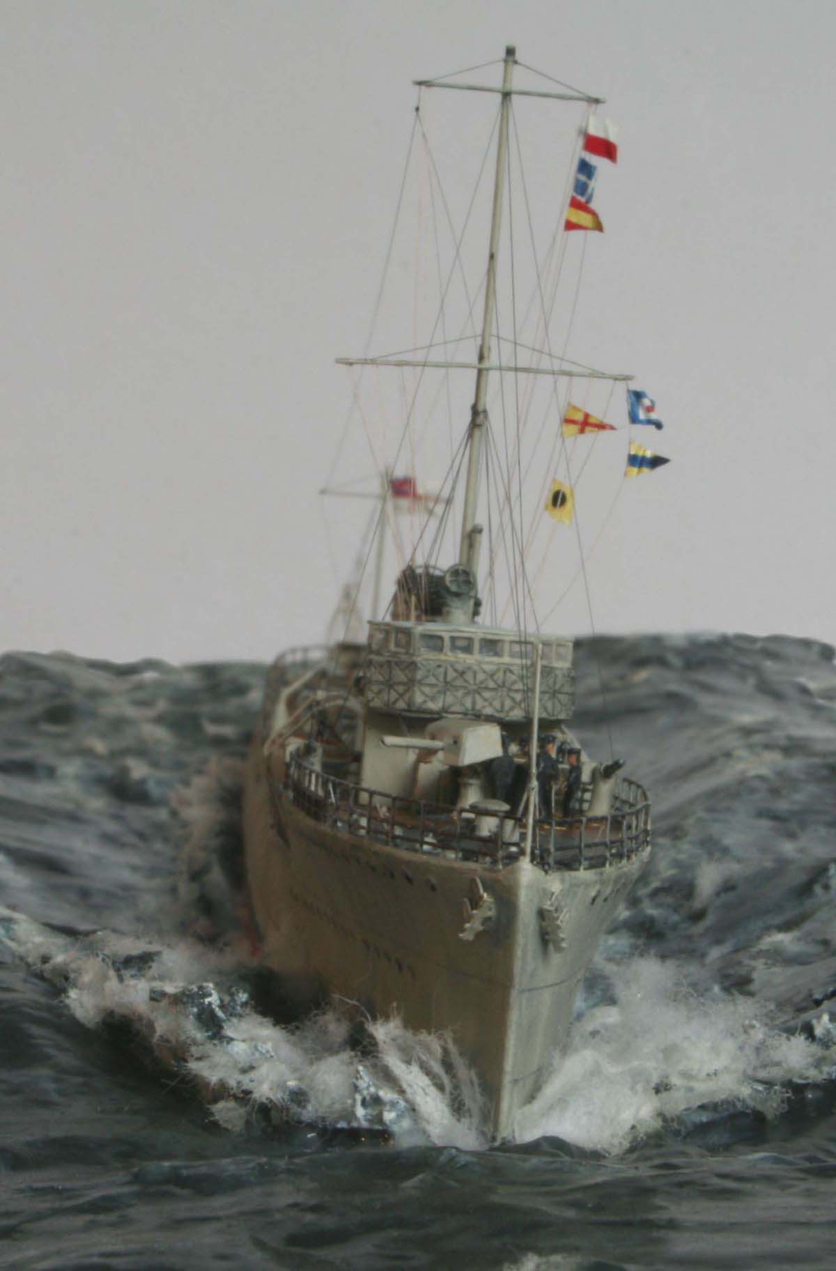
| The PE awning frame was installed--in view of the inclement weather I decided to deploy the awning for my bridge complement! I made the awning using white glue to span the frame, when set this was painted in the usual fashion. | 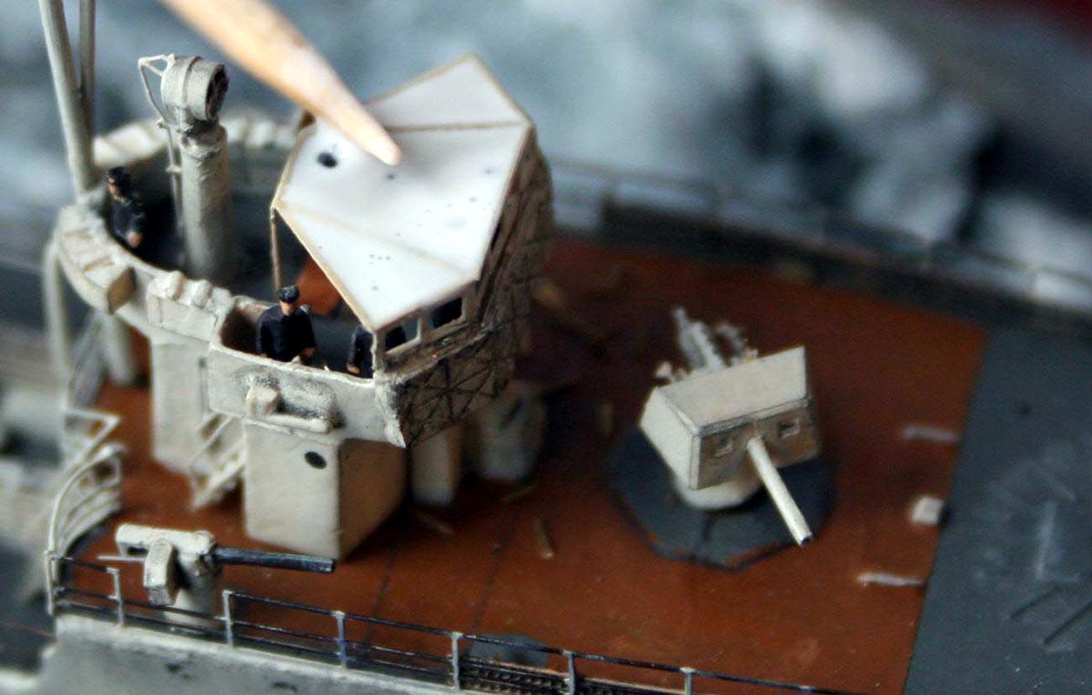 |
||||||||||||||||||||||||||||||
|
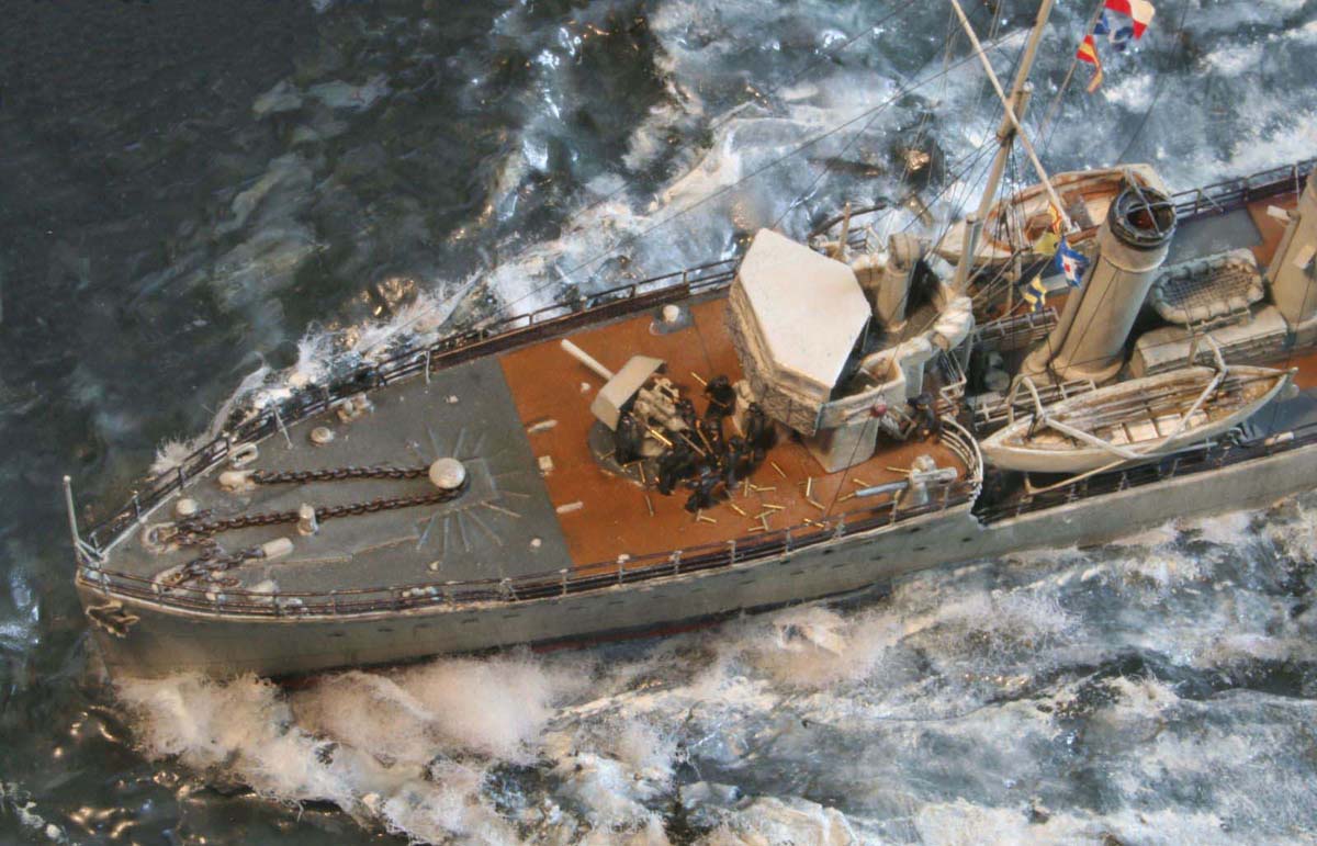
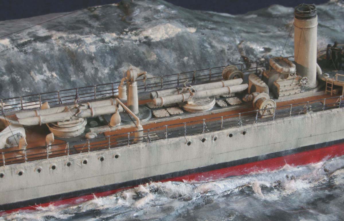
I chose to depict the ship engaging the enemy with her 4guns, in view of the seas running the crew are unable to operate the stern gun safely. The usual maximum rate of fire was 13 rounds per minute using this type of gun, judging by the shell cases rolling around the deck they have been at it for some time! |
 |
||||||||||||||||||||||||||||||
| The searchlights were mounted on pedestals they were operated via remote
control rods. These rods were supplied as PE items, I felt they were too
flat and fashioned replacements in copper wire.
The model was essentially complete and ready for rigging ergo ready for flat coating with matt varnish. Catastrophe struck I have flat coated my last 60 or so models using Humbrol Matt varnish from an aerosol can always with a satisfactory and guaranteed result. Not this time;- the varnish had the audacity to blister some but not all of the Cortisone paint and dried white in places . |
 |
||||||||||||||||||||||||||||||
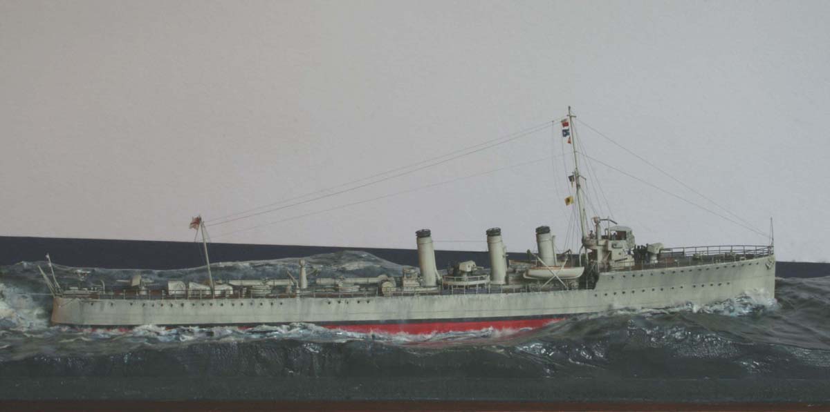
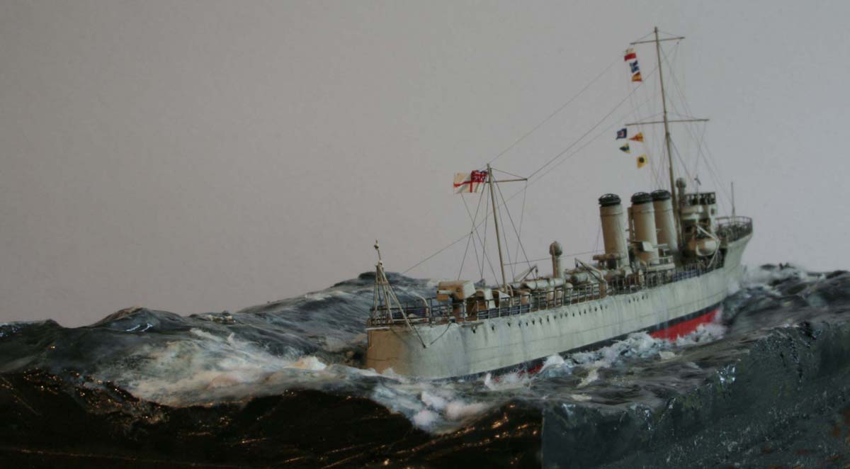
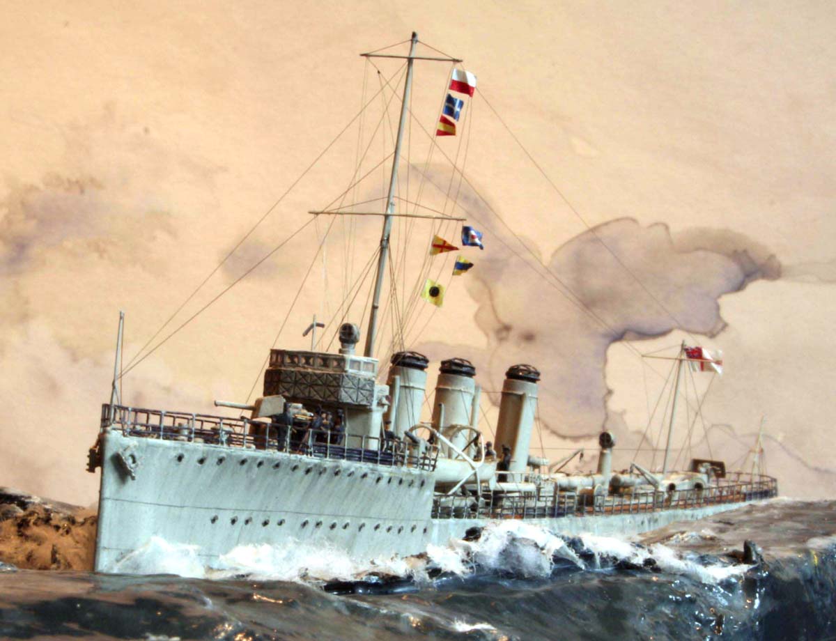
The ship was then rigged using black stretched sprue for standing rigging and tan stretched sprue for the signal halyards. I indicated the quartering beam sea and wind direction with the flags straining at their hoists . The spume coming off the wave tops, curling bow wave and flying water spray was simulated using torn paper and very very fine white fluff (from Tumble drier filter after white towel wash !) All in all a most satisfactory model to build; and unique in 1/350 as a representative of the sleek and dashing destroyers, whose incessant work in the war at sea in World War One was often overshadowed in accounts of history by the big guns of the Grand Fleet . |
|||||||||||||||||||||||||||||||
| References: | |||||||||||||||||||||||||||||||
|
 |
||||||||||||||||||||||||||||||
| More of Jim Baumann's work. | |||||||||||||||||||||||||||||||
![]()
© ModelWarships.com