by Jeff Herne
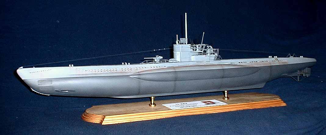
by Jeff Herne
When the Amati Type VIIB kit was released in the late 80s, I was a starving college kid who REALLY couldn't afford the $300 ticket price. When the price finally came down to $199 in the late 1999, my wife finally decided I had been patient enough and bought it as an anniversary present. What a nice surprise, especially when it's unexpected. It's 2003, 4 years later, and it's finally done.
The Kit:
The kit comes in a large, nicely printed box featuring a built-up U-47 on the cover. The packaging of the model is impressive, the all of the parts are bagged, and the large sheet of photoetched brass sits nicely on the bottom. When I reviewed the contents of my kit, I was impressed at the casting quality and the crispness of the parts, but annoyed at the complete lack of detail on the resin hull. There is a full sheet of plans showing profile view and sub assemblies, and a detailed instruction booklet covering the balance of the assembly. The history of the U-47 is represented in multiple languages, unfortunately, that's the extent of the English. The balance of the instructions are written in Italian. The drawings are very difficult for the average modeler to comprehend as it seems there are contradicting instructions on the plans sheet and plans booklet.
Decisions, Decisions:
I've always enjoyed models with 'clutter', which is probably why I spend most of my time building ships. The kit represents a pre-war to early-war Type VIIB, and out of the box, you can model most of the famous U-boats, including Kretschmer's U-99, U-48, which was the most successful U-boat of the war, Prien's U-47 and Schepke's U-100. These boats carried the original conning tower with a single 20mm AA gun located on the aft deck, and an 88mm deck gun. (This 88 was not the same 88 used by the Wehrmacht and Luftwaffe, the bore was the same, and the similarities ended there.) By 1943, U-boats began carrying different 'Turmumbau', additional platforms added to the conning towers for additional AA weapons. By 1944, the Turm IV was in widespread use, featuring twin 20mm mounts on the upper platform, and a 37mm or quad 20mm on the lower. In most cases, when boats received these additional AA fits, the deck gun was removed to compensate for weight. There were exceptions to the rule, and this model fell into the 'exception' category.
I decided to build a 'rare' Type VIIC that carried the 37mm on the Turm IV, yet retained the 88mm deck gun. My boat, U-242, was commanded by Oblt. Karl-Wilhelm Pancke and is modeled as she appeared in January of 1945, just prior to her loss. The external differences between the VIIB and VIIC amounted to a difference in length of 6/10th of a meter, or, about 1 scale foot in 1/72nd scale. I decided not to worry about it too much I doubted that anyone would be scaling her with a 1/72nd scale ruler. I realized the conning tower would require a major facelift, and I would need to scratchbuild the additional platforms and railings, and find the additional weapons. With my decisions made and the course set, I set off to work.
Researching the modifications:
Like any project, I spent a great deal of time researching the changes I was going to make to the model as I went along. Major design changes would have to be made to the conning tower, so I gathered my resources, which I will provide here. The most beneficial piece of data that I have for this project are a set of builder's plans for a Type VIIC and my collection of U-boat photos. I scanned the midships sections and scaled them up to match the dimensions of the model. I printed several copies and used them as templates for the shapes and dimensions of the 'Wintergarten' platforms on the rear of the conning tower. It also gave me a very good perspective on the angles of the rails and other small details.
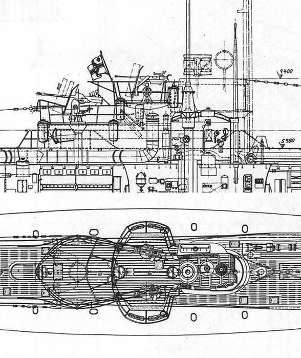
Type VIIC Conning tower plans
My other sources included 2 websites, www.fineartmodels.com and www.u-boat.net. Fine Art Models sells an expensive 1/96th scale late war Type VIIC boat, and I matched my builder's plans against their model and it looked very close. I also contacted them and found we were using common plans and research materials, so I felt confident in using their model as a source of data. U-boat.net provided a lot of technical information, dimensions, histories, and the folks in the forums were extremely helpful. Special thanks go to Ranier Bruns for researching the Turmumbau configuration for me, and the webmasters of the U-99 and German U-boatwaffe sites for the added help. I also want to thank the staff of the German U-boat Archive in Germany for verifying the configuration of U-242. Of great assistance are the photos of U-995 at Laboe, Germany, and of U-505 at the Museum of Science and Industry in Chicago. Although U-505 is a Type IX boat, many of the fittings are the same, which helped immensely with details. I also recommend Blair's extensive 2 volume set Hitler's U-boat War, and Wynn's 2 volume set on U-boat Operations in WW2.
The Incredible 1/96 Type VIIC from FineArt Models
One of the first things I noticed in researching they Type VII was the dramatic differences in the tower configurations of the boats from 1942-45. Unless I could find some first hand evidence (photos) that Type VII towers were updated and not replaced, I would have to scratchbuild a new conning tower. Fortunately, I did manage to find some photos that supported my theory that many conning towers were not completely rebuilt, but rather, were fitted with whatever was required or available at the time. So I took the approach that my boat was simply upgraded, not completely rebuilt. I started altering the conning tower accordingly
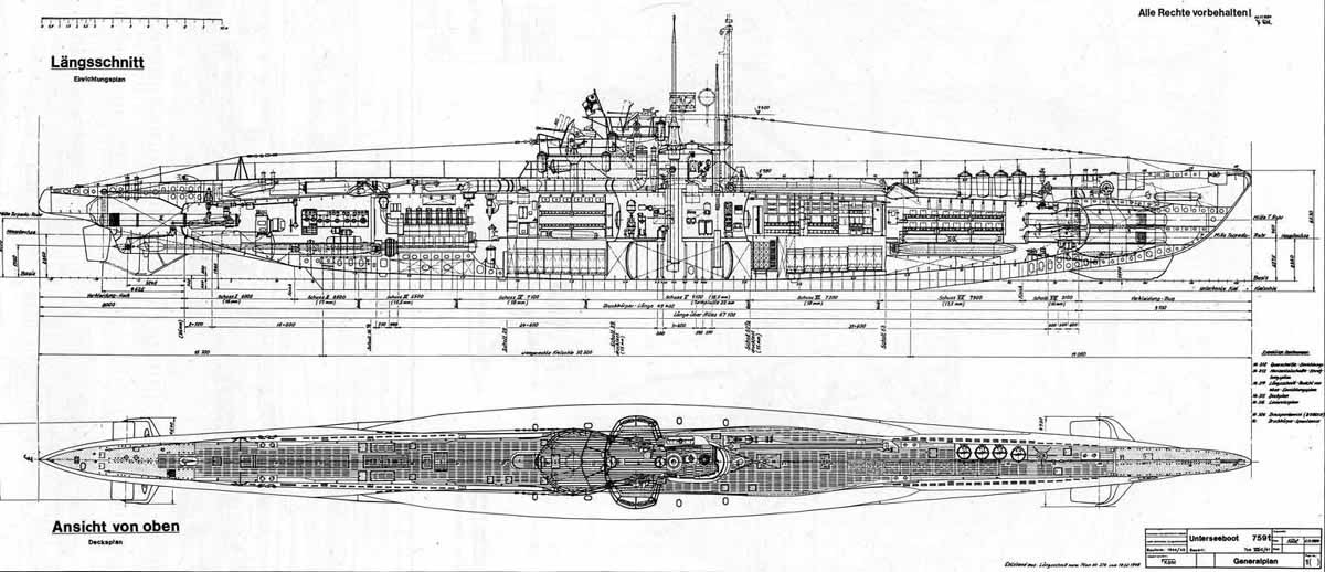
The Hull:
The hull of the boat is a single cast piece of resin. My hull is hollow and foam filled, making it lighter, but conversations with other kit owners have revealed that the early releases were solid. Either way, at nearly three feet long this a big piece of resin. The hull is noticeably bereft of all detail, there are no limber holes, panel lines, or weld seams. These will all have to be added by the builder later in my case, a straight edge and drafting pencil. The upper deck plates are provided in the photo-etched parts, and laser cut wooden bulkheads are provided. The parts require minimal cleanup, but here's where I ran into my first trouble. The kit comes with 2 sections of wood that would equate to a keel beam if it were on the bottom of the hull. These 'stringers' rest on the cut-out upper portion of the hull and form the spacers for the bulkheads, which in turn provide the shape for the brass hull sides and deck. I noticed each part fit snugly into the stringer, and fit nicely with minimal pressure. However, after adding 8 bulkheads, the once-level stringer now developed an obvious bow doh, I screwed up Time to think about this.
After attacking each bulkhead with my trusty Dremel and steel cutting wheel, the parts dropped nicely into the stringer, and the bow is done allowing the parts to be glued to the resin hull. Be sure to mark your distances and make sure you're equidistant on both sides of the beam, you will need to add the photoetched side pieces shortly. When both stringers are joined, it becomes obvious (at least on my kit) that the hull is shorter than the wooden assembly it's supposed to join to by about ¾ of an inch ok what did I do wrong this time? I went back and checked and re-checked, but the hull seems too short. What to do? I have two choices, I can shorten the wooden assembly or lengthen the hull. Since the hull is accurate in length, I decided to cut down the center of the wooden assembly and remove a section of stringer between two bulkheads. This insures I have the proper shape, and I cut the section from the rear half of the assembly which has a relatively consistent taper towards the stern and now things fit, sort of the curvature of the deck and the lack of opposite curve on the stringer makes for a terrible fit.
On the stern section of the hull, aft of the conning tower, I removed the horizontal stringer altogether and glued the vertical bulkheads into place. I then added some sheet plastic in between each bulkhead to block out the ability to see straight through the boat. Once the wooden pieces are laid down on the hull and secured, check the level of the deck. It must be level otherwise, the brass sides won't match properly to the deck. Amati provides the builder with seven sections of heavy brass, three for the deck and four that make up the sides of the hull. I test fit the side pieces and marked off on the hull the locations of the seams. I then started at the bow and worked towards the stern, fitting the brass to the bulkheads and attaching with CA. This is a lengthy process, as you have to be sure you twist and bend the brass sides properly. I eventually had to heat the brass to anneal it, forcing it to retain it's shape once bent. If you mess up, you will have major fit troubles in the conning tower area. I eventually developed a system whereby I would glue the brass to the lower half of the bulkhead and leave the upper section of the part unattached. This allows the deck to be mated up later on.
Once the first pair of side parts were in place, I attached the deck. Although the instructions say to glue these parts, I decided to solder the parts together. There's simply too much torsional tension on those sides parts, and inevitably, they are going to let go in the future. I used .040 silver solder and a conventional soldering iron to spot solder the pieces together. Once in place, I filled the seams with solder. I ground the heavy solder with a sanding disk in the Dremel, then sanded the joints with 400 grit wet-dry paper and then polished with 600 and 1200 followed by a buffing wheel in the Dremel, and the seams now look incredible. I followed the same procedure for the after sections and found it to be easier as I moved farther aft. I highly recommend soldering the brass deck sections, as it provides far more structural strength to the model.
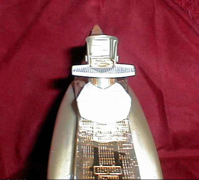
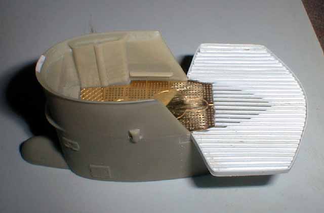
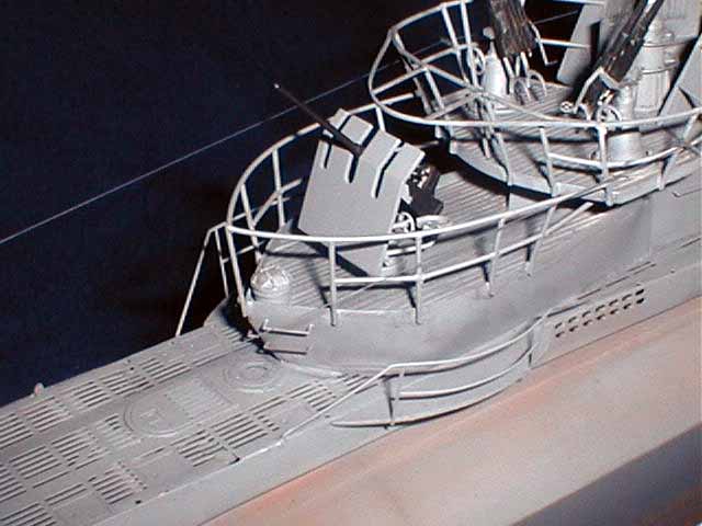
The Conning Tower: First thing I needed to do was to add the additional extended platform to the rear of the tower. This was done by cutting the platform from .080 sheet, tracing the outline of the rear of the tower, and cutting the opening. I then glued and blended the platform into the rear of the tower.
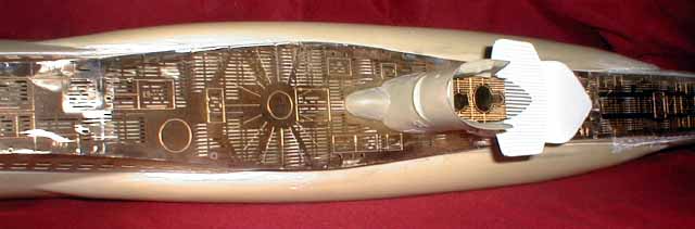
From here, I decided to do a mindless task and plank the deck while watching football 3 packages of .020 x .030 plastic stock, a bottle of Tenax 7R and my handy chopper and about 60 minutes of work.
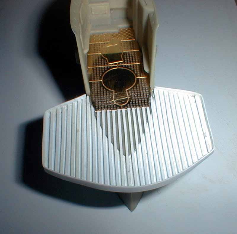
The next step was the lower level of the Wintergarten. This is, without a doubt, the most complex part of the entire project. The platform viewed from above is shaped like an arrowhead, not too difficult if the side walls were perpendicular to the deck. They're not, they're sloped inward, about 5 degrees inward at the front, to about 12 degrees outward at the rear of the platform I test fit several pieces, and finally got a basic idea of the shape I needed. I then scribed and cut a mirror image, and attached the upper portions to the platform. I reinforced the internal structure, determined my proper height from the deck, and draw a line using the deck as a guide. I then cut the access from the bottom, sanded the entire platform in my kitchen sink under running water (and a flat surface), and finally glued the entire assembly to the deck.
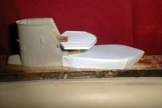
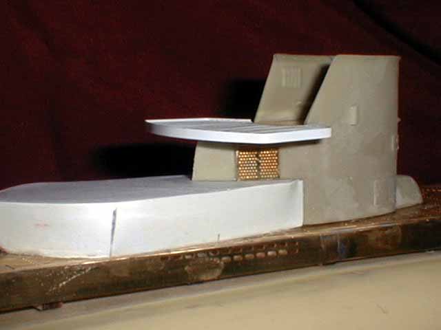
. I planked the lower level of the Turm in the same manner as I did the Wintergarten, and added a .020 x 1/16th strip around the outside to form the deck edge. (insert turm lower pic here). At this point I cut the recess into the planking for the 37mm mount as well. The next step was the radar detection housing. I used Plastruct stock and sheet to build the housing, and shaped the inside of those parts to match the exterior contours of the tower. A piece of brass sheet forms the upper outer cover, and the opening was framed in with plastic strip.
Now came time for the array. German U-boat radar detection gear is confusing. They used all sorts, some were successful, most were detrimental. Going to my photos, I found several shots of various radar detection arrays. I chose to model one that would prove to be the easiest to replicate. It came in the form of a set of HO gauge model railroad ventilation screens for a diesel locomotive. The pattern matched well and the shape was correct. I added the dog-bone insulators from unfolded pulleys from a GMM 1/350 USS New Jersey set. The assembly consists of 14 parts not including the wire bundle running from the center of the array into the housing. Once I sanded the outer portion of the housing, I framed in the opening with various bits of plastic strip and stock.
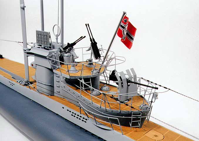
Bridge Detail, Railings and Periscopes:
Examination of the bridge parts revealed a well known fact in resin kits; no matter how well you cast resin you can never achieve straight gun barrels, prop shafts, masts, or periscope housings I replaced the periscopes with turned brass rod, and added in the taper with a rounded mill file while the stock was still turning in the lathe. The periscope housing features 2 steel platforms for lookouts, these needed to be trimmed to match the diameter of the housing. Once in place, they were tacked underneath with CA. I replaced the mounting pedestal for the UZO (Targeting binoculars used for surface attacks) with brass tube and attached the kit parts to that piece. The hatches, handwheels, and all other parts were added as per kit diagrams. Railings: The railings surrounding the Wintergarten are a pain no matter how you look at it. The photoetched kit parts no longer fit, as they designed for the unaltered conning tower. Soldered brass rod proved to be too risky, as the heat from the soldering tended to cause the surrounding plastic and resin to melt I couldn't pre-fabricate the rails and then attach because of the compound angles and curves. Gluing brass rod just didn't bode well with my inner conscience. After several attempts at various proven methods, I finally settled on .030 and .025 plastic rod. Surprisingly, it's easy to work with, a little pressure produces the necessary bends, and it's easy to cut and twist. Once the uprights were in place, the upper level of the Wintergarten took only 6 hours to complete, the lower section another 12 or so from start to finish. Each section of the rail is an individual piece, as seen in the detail photos in my collection. With the railings in place, and the additional restricting supports to prevent the 37mm from firing at dangerous angles back towards the tower, the conning tower is finally beginning to take shape.
Weapons:
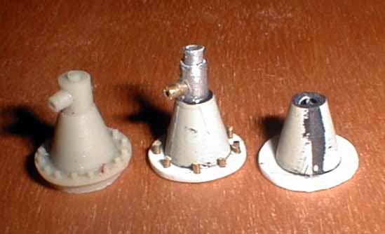
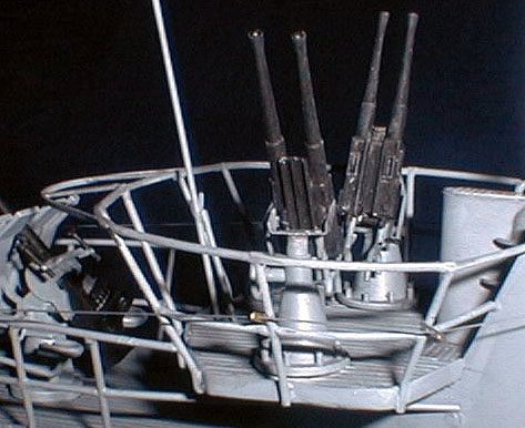
Type VIIC boats carried a variety of weapons, and, aside from the unsuccessful U-FLAK series of boats, U-242 was one of the most heavily armed Type VIIs to be built. She carried two 20mm twin mounts on the upper level of the tower, and a 37mm AA gun on the lower level. She also retained her deck gun, since her area of operations in the Baltic consisted of smaller Russian coastal targets, many not worth wasting an expensive torpedo. I purchased the new Revell S-100 torpedo boat, and used the 37mm AA gun and mount with minor modifications. The breech and barrel of the Revell 37mm are poor, so I scrounged a Hasegawa 37mm from the 1/72 scale Ostwind and replaced the weapon. Results are much nicer, although now I have a Schnellboot and an AA tank with no weapons!! I also purchased a Hasegawa SdKfz halftrack with a 20mm Flakvierling. This provided me with the 4 C/38 20mm barrels and breaches I needed to update the mounts on the upper level. I used the twin 20mm mount in the Revell S-boat to pattern my own mounts. Initially I thought of nice machined brass pedestals for the 20mm, but realized (at 1am) that I didn't have brass stock large enough in diameter. I scrounged through the parts box until I found a set of drop tanks from a 1/72 P-38 Lightning looking at the cross section, I realized the taper was nearly perfect. Cut and affixed to a plastic disk, drilled and fitted with a steel tube, it began to look like a mount. I drilled holes in the base and inserted brass rod to simulate the mounting bolts. The kit part has 16 bolts, but several photos of mounts on actual U-boats show considerably fewer, so I settled on 8. I drilled the steel tube and inserted a piece of smaller tubing for the elevation wheel, and a second tube within the larger one to simulate the shaft of the mount. (insert mount stage pic here) I was pleased enough with the results of the mounts. After reviewing some photos of the actual breeches and mounts, I fabricated a mount for the twin barrels, and looked for a way to affix the mount to the pedestal. I settled on a little 'Gizmology' since I needed a part that I didn't really have good references for, and would end up being tough to see once completed anyway the mount turned out to be 1/350 US Navy Mk 12 Fire control radar supports from Tom's Modelworks, once folded, they match the width of the gun mount perfectly, and are already recessed with locations for the mounting for the radar array, in my case, it was the balance point of the guns. I added a strip brass arm for the gunsight, a 1/48 aircraft ringsite, the elevation wheels, and the wiring harnesses.
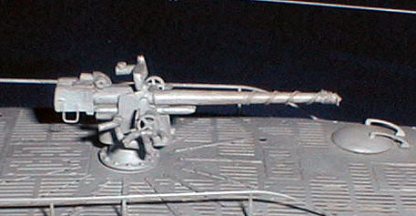
The 88 mm deck gun in the kit just doesn't look right it appears to be too small. My measuring of the height of the mount determined that the carriage was ok, it was the breech and barrel that were too small. Another search through the spares parts box found a Roco 1/87th scale 10.5cm artillery piece. The breech was more detailed, and about 7% larger than the kit part when I layed the Roco part over the scale drawings, it's far closer to the plans then the kit part good enough for me! I cut the barrel off and turned a new barrel from brass. The kit parts for the restraining arms for the gun crew were grossly oversized and complex, at one point I felt like a 1/72 scale plumber, trying to get cylindrical elbows and u-joints to align properly. The kit parts were retained for use as templates, and I soldered brass rod into the correct shapes for the arms. I added a scratchbuilt sight and replaced the elevation wheels with photoetched parts.
Finishing Touches:
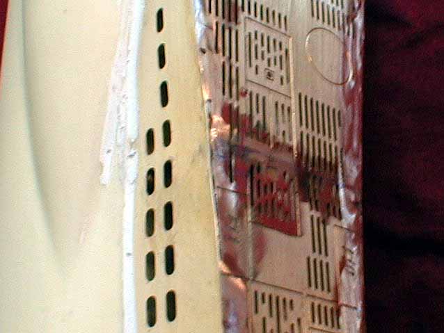
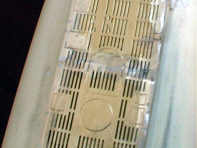
With the major subassemblies completed and the boat ready for primer, I went over everything one last time. I had originally intended the net cutter to be installed, but conversations with the U-boat Archive led me to remove the assembly after I spent 8 hours soldering it together and replacing the vertical supports, which were too short. At this point, I marked out the locations of the torpedo tube doors, and added .008 strip to simulate the out doors. I had initially intended to scribe the doors in place, but my patience with the project was beginning to wear thin, and I opted for the 'easy' method. During this phase I also marked off the limber holes and drilled them. The circular holes are obviously quite easy, the rectangular holes proved to be a bit tricky. The instructions suggest that you use the side brass pieces of the hull as templates for the holes prior to installing them. Since I didn't read that little caption in Italian, I neglected to do that instead, I bought a drafting eraser template from the local art supply store. This little template allows draftsmen to protect the rest of their drawing while erasing small details. It cost $1.25, and had several shapes perfect for marking out the limber holes. Once marked, I drilled two holes per rectangular limber hole then used an X-acto with number eleven blade to open the remainder of the hole. This painful process was the longest part of the construction, with about 30 hours of drilling and cutting to get the necessary holes. I intended to open the bottom of the hull, but after counting more than 120 holes on the underside of the ship, decided to just let it go as is.
Painting and Weathering:
The guns and periscope housing were removed from the tower, and I sprayed the hull and conning tower with primer, revealing some pin holes, rough textures, and scrapes. After 3 days, I wet-sanded the entire hull and deck with 600 grit paper, and touched up a few rough areas with surfacing putty. A second coat of primer, another 3 days to dry, another 600-grit wet sanding, and it's ready for paint. I decided to go with the 2-tone gray scheme used by late war boats, and chose Tamiya German Gray and US Neutral Gray for the colors. I added some light gray to the German Gray, and a touch of IJN Gray to the US Neutral Gray to give it just a hint of blue tint. I masked and sprayed the hull and fittings in one evening. To expedite the process, I'd spray the acrylic and then hit the wet paint with a hair dryer. Since I sprayed indoors on a rainy day, I wanted to make sure the paint skinned quickly and didn't develop any haze. After the base coats were applied, I sprayed a coat of light gray over the upper surfaces, then added a black wash. Finally, I dry-brushed the raised details with the base color of Neutral Gray. On the lower hull, I drybrushed Tamiya Dark Gray over the German Gray, which brought out the detail nicely (Tamiya German Gray is darker than Dark Gray). I added some rust to the limber holes (actually, a lot of rust) with pastels, and added in the panels lines with a number 2 pencil, then lightly erased the lines, leaving a faint pencil line. I drybrushed the line with black pastel, then drybrushed a wider line with a gray that was darker than the upper surface but lighter than the lower hull color. Once that was completed, I Dull-coated the entire model, repeated the rust process, and Dull-coated a second time. The results are very subtle blending of the pastels into the base colors, since the initial clear flat killed much of the contrast caused by the weathering. The second application of rust brought it back. The model was then attached to a stained base with the brass finials included in the kit, and I printed a data plate on full sheet mailing labels. I included the Flotilla logo, and then attached the entire label to a 4x6 piece of sheet styrene. Once attached, I applied several coats of semi-gloss clear right over the paper. I then attached the plate to the base with 6 brass nails.
Conclusion:
I must say the model definitely captures the true lines of the Type VII better than any kit I've ever seen. That being said, I will probably never build this kit again. The design of the layout of the kit is poor, and the true multimedia nature of this kit, with resin, brass, wood, and with me adding plastic rod and strip, and aluminum and steel, make it a tough build for all but the most experienced of modelers. The primary areas of concern are the mating and blending of the brass structure to the resin hull, and getting the proper contours of the brass sides of the hull. Other problems include the complete lack of detail to the resin hull. One would almost be tempted to detail the resin hull for use as a pattern for a vacuform copy. The small increase in size of the vacuformed hull over the resin one would only help to resolve the problem of the wooden bulkhead assembly being nearly ½ inch too long for the hull. At least with a vacuform hull, the drilling and scribing of panel lines would be easier. The model took about 450 hours to complete, from the initial opening of the box to the completion of this article.
The next project should be simpler...a Revell AG Schnellboot...with
some 'minor' conversions!

© ModelWarships.com