|
German Fast Attack Craft S-100 Class 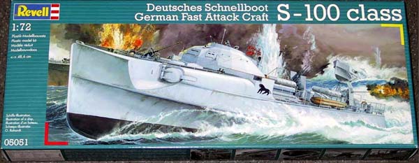 |
|
|
|
|
|
Something Special about S-100 Class The Lürssen-Effect The rudder configuration and propeller shape and position on S-100 are designed to create the "Lürssen-Effect"named after the designing shipyard of S-100 in Vegesack, Germany. While the Main Rudder is designed for steering only, the angle of each Trim Rudder can be individually adjusted. In PHASE I the rudders are kept parallel for standard cruise. To create The Effect the vessel must run faster than 25 knots. At this stage the trim rudders are turned 30° away from the centre line (PHASE II), causing an air cavity right behind them (yellow marks), resulting in a change of stern current-velocity and -direction as well as the depth of the stern diving down into the water.  Sub-Effect 1: Due to the reduced current velocity right before
the Trim Rudders, the effective propulsion force of the propeller gets
higher without the crew having to increase the rpm of the engine. This
may gain an additional speed of more than 1 knot alone.
Once the Effect has been reached the Trim Rudders can be turned back to a 17° trim without having the air cavities collapsing (PHASE III). This doesnt increase the speed any more by itself. The effect will now be stabile, even if the speed is reduced to 20 knots. At the 17° trim the maximum speed can be reached. On several test runs on the Lürssen-Effect, the same vessel ran 40,2knots top speed without trimming the rudders, but 42,4 knots with 17,5° trimmed rudders. An increase of 5,5% in top speed without additional use of gas! |
|
|
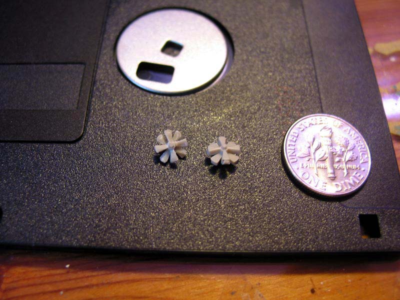
... To calm down myself about the possibility
of having ruined my kit with the stripe camouflage pattern, I turned myself
to something completely different. The propellers of the torpedoes supplied
by Revell are a mess. First I tried to scratch build them by cutting their
shape out of a brass sheet, but it didn't work out, because I couldn't
achieve to shape even blades on them with my set of tools. So I turned
back to the propellers supplied in the kit. By cutting and sanding I made
them usable, even though the keen observer will see that the screws blades
are not counter rotating.
|
below to enlarge |
 |
|
| Now it was time to reveal the product of my masking and spraying orgy. Removing the roughly 150 masking strips took quite some time, but the result was very satisfying. The surface of the hull was kind of uneven, because the color had built up in layers of varying thickness. Spray painting the hull with flat coat solved that very nicely. | |
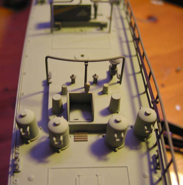
| Fitting our the forecastle was done following the instruction by adding fittings, railings, anchor, gun mount hood and forward 20 mm AA gun. Application of some chain to the anchor and rigging yarn to the anchor and gun mount hood, as proposed by the instruction added some nice detail depth. | 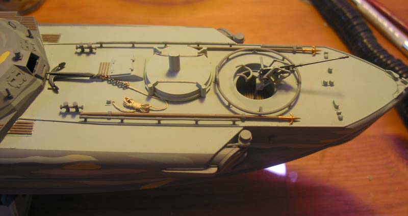 |
| At this stage I decided on the following paint scheme:
All decks fittings I would paint in Mix 3. Exceptions to this rule would be: - compass house, fog cans and major horizontal surfaces like the gun mount hood, painted in Mix 1 - all gun mounts and gun mechanics (Mix 1), guns and anchor (Mix 7) - wooden structures and details like boat hooks and wooden platforms (Mix 5/Brass color) - Torpedoes (Brass color/ Mix 7/ Black) Major vertical structures like gun shields and engine hood sides would be done in the camo scheme same as the hull, excluding the sides and back of the bridge to avoid a too crowed look. |
|
| As I went along to fit out the with bridge armor I came across a very common problem with Revells kits: Sooner or later some part is not going to fit, but a little putty fixed that right away. | 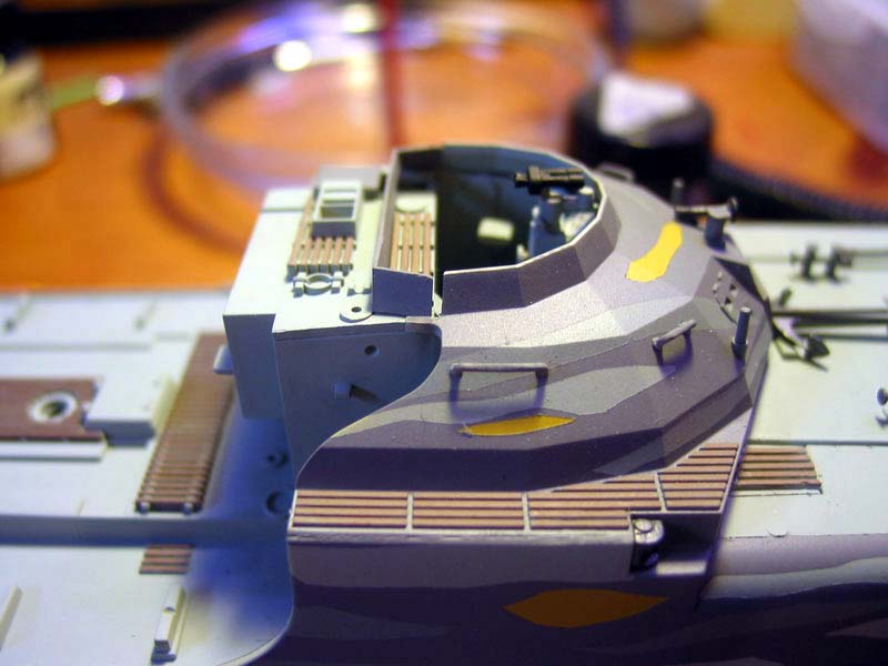 |
|
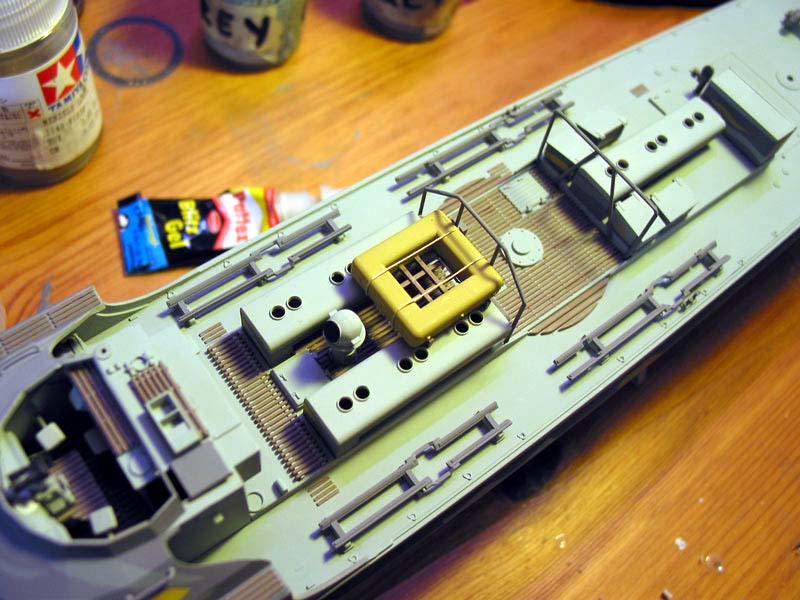
At this stage I decided to leave away the platforms and antennas on the bridge, because the are too prominent to stay in place until the end of construction. Leaving the order of the construction manual I went right on the main structures on the quarter-deck such as decks boxes and engine hoods and. Torpedo racks, struts and life raft (Mix 4 + a few more drops of Deck Tan (XF55)) came next. Again following the recommendation of the manual, I added some rigging yarn on the life raft. |
 |
 |
|
 |
|
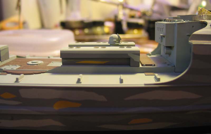
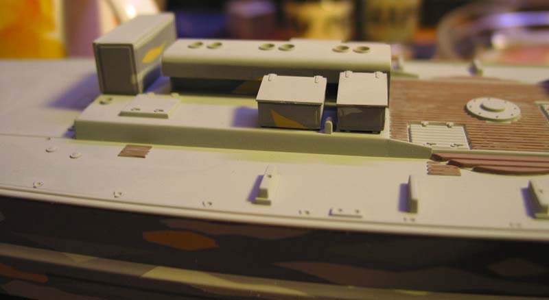
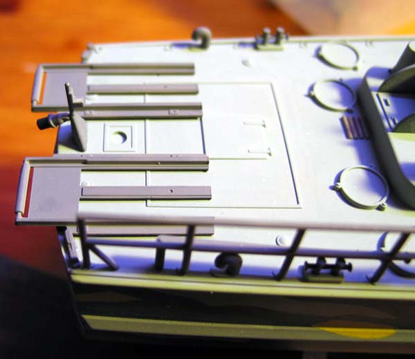
| As I told you Part 1 of this build-up review, I didn't want to settle on the choices of mine rack/fog can configuration given in the construction menu. Instead, inspired by the ship's plans given in my reference book, I cut away the end of the racks to fit right behind the stern engine hatch and giving me enough space to place all four fog cans provided in the kit. | 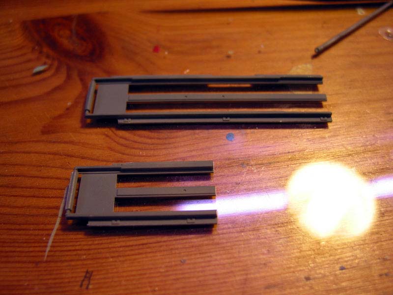 |
 |
|
 |
|
|
to be continued.
|
|
| Guido Hopp
Düsseldorf, Germany guido-hopp@hopp-import.de PS.: Ill be glad to give information/help to everyone on the message board of this page. Back to menu
|
|

© ModelWarships.com