by Ed McDonald
| THE DDR | |||||||||||||||||||||||||||||||||||||||||||
The Destroyer Radar Picket Ship (DDR) was invented in late 1944 to address new needs. The Imperial Japanese Navy was gone destroyed at the Philippine Sea and at Leyte Gulf. There was little remaining need for quick and nimble fast destroyers making daring night torpedo attacks on massive battleships and heavy cruisers. The very ships that had destroyed the Japanese fleet had, by doing so, made themselves obsolete. The new threat was the kamikaze. A ship was needed that could patrol the far fringes of the fleet, was heavily outfitted with new advanced height finding radar, could provide early warning of a kamikazes arrival, carried the equipment, radios and radars required to vector CAP (combat air patrol) fighters to interceptions, carried the equipment to distinguish friend from foe and was heavily armed with anti-aircraft guns for self defense. Chevalier was one of the first DDRs to be completed. Immediately after her conventional construction, she was refitted as a DDR. The Gearing class was selected for this particular conversion because it was the only destroyer class large enough to accommodate the changes and also to have a long enough range to be able to operate essentially independently for lengthy periods. There were actually at least two major variations of the DDR. This model of Chevalier is the earlier 1945 variant. In 1949 and 1950 the DDRs were upgraded with the improved SPS-8 radar which was too heavy for the tripod mainmast and required its removal. It actually was not until that time that these ships (including Chevalier) were actually officially reclassified as DDR. Until then, Chevalier was known simply as DD-805 or today as DD(R)-805. In reality, the DDRs had little impact on WW2. Chevalier didnt arrive on station in the Pacific until 1 July 1945. Her only action was in support of a bombardment of Wake Island on 1 August. After that she joined TF 38 entering Tokyo Bay for the Japanese surrender. Nevertheless, the idea was nearly prescient and after the appearance of the high speed jet fighter/bomber during the Korean War and the early Cold War, the DDR quickly evolved into the fleets most important early warning tool of the 1950s.
| |||||||||||||||||||||||||||||||||||||||||||
| THE KIT | |||||||||||||||||||||||||||||||||||||||||||
This model was built from the Dragon USS Gearing kit. The Dragon Gearing kit is, with no question, the best plastic ship model kit that I have veer built at this scale. Certainly it is the most complete and most highly detailed that I have ever seen. I cant vouch much for its detailed accuracy as Gearing since I built it as sister ship Chevalier after her DDR conversion, based largely on as built plans from May 1945. But, the overall detail is at times quite astonishing and since I assume that required considerable research, it must be quite accurate. But, it is not without some difficulties and confusion. This document will attempt to explain and detail those points. The first issue is that out-of-the-box there are unfortunately only a few ships in a very limited time period that can be built from this kit without some modification. I will mention that the kit contains many additional parts. If the differences between ships are minor such as different quantities of 20mm guns or life rafts, the kit can probably accommodate it. But, before the construction of many early Gearings was even completed, they were already being converted to the DDR design. That change included additional radars a new tripod mainmast and landing of the torpedo tubes as well as many other more minor changes. Chevalier was one of the first of these conversions and will require a good deal of scratch building. I chose Chevalier because detailed plans were available, she was one of the few Gearings to actually play some role in World War 2 (minor as it was) and because she was camouflaged in the attractive 1945 MS-22.
| |||||||||||||||||||||||||||||||||||||||||||
| THIS REPORT | |||||||||||||||||||||||||||||||||||||||||||
Other excellent build-up reports have already been written about this kit. You may find this document overly lengthy and overly detailed. But that is the way I build model ships. In an effort to speed up your use of this report, I have indicated problem areas or points of confusion in the kit in bold type. And, as is common for Dragon models, the instructions are the worst part and attempt to spoil an otherwise superlative kit. I must say that they do seem to be improving in both accuracy and detail. But there are still far too many situations where the instructions are vague, poorly drawn, confusing or misleading (usually because arrows point to the wrong location) and require a magnifying glass to just get an idea of whats going on. We have come to expect to work almost entirely from plans for poorly instructed resin models. But, in this case there are no plans to which to refer unless you buy them separately. If I had not had Chevaliers plans for my use, I have no doubt at all that many parts would be installed incorrectly, upside down or just in the wrong place. We dont expect that in a plastic kit. In order to be satisfactory to the masses, Dragon really needs to correct that problem. If printing costs are an issue today, perhaps they should try delivering an instruction CD, as the software industry began doing over a decade ago.
| |||||||||||||||||||||||||||||||||||||||||||
| MATERIALS USED | |||||||||||||||||||||||||||||||||||||||||||
| |||||||||||||||||||||||||||||||||||||||||||
| CAUTION ON REQUIRED RADARS AND ANTENNAS | |||||||||||||||||||||||||||||||||||||||||||
To build a DDR you are going to need some relatively rare radars and antennas that are not included in either the kit or the GMM PE set made for the kit. Specifically:
You can get all the PE radar parts you need from the USS Essex GMM PE set, although the SP radar is the only really critical part (and technically speaking it still needs some modification). But, it is that specific radar that made the DDRs unique. I mention all of this since if you have ever used GMMs Essex PE set or any GMM Battleship PE set, you may well have these parts leftover. And, of course, there may be other sources. Just be aware that to build a DDR you will need them or you will need to scratch build them.
| |||||||||||||||||||||||||||||||||||||||||||
| RESOURCES | |||||||||||||||||||||||||||||||||||||||||||
I would also like to thanks Dave McComb of the Destroyer History Foundation and Sean Hert of ModelWarships.com for their research and advice.
| |||||||||||||||||||||||||||||||||||||||||||
| GENERAL CONSIDERATIONS | |||||||||||||||||||||||||||||||||||||||||||
This build does require skill and patience. Many of the parts are amazingly small and difficult to work with. Other build-up reports have been posted about this kit and I will not attempt to repeat every detail in this report. Also, please note that I will NOT be assembling this kit in the order suggested in the instructions. Rather, it will be assembled in a logical bottom to top, inside to out sequence, and hopefully therefore will allow easy access to all parts and details. I will also be detailing the build to the maximum possible extent. Ill be using photoetch in all possible locations with a general preference for the finer detail GMM PE over the thicker PE supplied with the kit. Ill also be adding quite a bit of scratch built (styrene and brass) detail as indicated by the plans. And of course, I will be scratch building the tripod mainmast and the radars and antennas mounted on it. If you feel shy about this, perhaps you should build this kit as Gearing, which requires no scratch work. This build is being modeled for the summer of 1945 as Chevalier made her way with TF38 to Tokyo Bay for the surrender ceremony.
| |||||||||||||||||||||||||||||||||||||||||||
| PAINTING | |||||||||||||||||||||||||||||||||||||||||||
During the modeled for period, Chevalier was painted in the classic MS-22 camouflage. But in 1945, due to a world-wide shortage of indigo pigment, that measure was adjusted to be considerably less blue than it was during the majority of the war. Ships already in commission dealt with the issue by extending their paints by mixing them with gray, which resulted in a good deal of color variation and splotchy paint jobs. Its obviously difficult to judge just how much grayer Chevalier was from the black and white photos of the time. But, in 1945 the Navy had designated a few new colors to deal with the shortage of blue paint and I will attempt to duplicate them here to match Snyder and Short's color chips. Navy Blue (5-N) was replaced by #7 Navy Gray which was obviously less blue, but was designed to have the same spectral qualities as Navy Blue. So its a dark gray with just a hint of blue. Deck Blue (20-B) was replace by #4 Deck Gray (20) which was somewhat darker and less blue. In fact it looked nearly black. Haze Gray (5-H) was replaced by #27 Haze Gray (5-H) which was considerably less blue and comes quite a bit closer to the obviously gray Haze Gray of later years. I have no way to be certain that Chevalier carried these colors. But Ive painted so many decks Deck Blue and hulls Navy Blue that the change will be a welcome one.
| |||||||||||||||||||||||||||||||||||||||||||
| STEP 1 - THE HULL | |||||||||||||||||||||||||||||||||||||||||||
The hull is simple enough. The lower hull is detailed in step 5 of the instructions. Add the rudders and screw shafts. Ill wait and add the fragile screws much later. Also add the sonar protuberance (should it be called a dome?), part C11 from step 6, at this time. Paint the lower hull Hull Red. Paint the screw shafts Brass. At this time the only thing to add to the upper hull half are the screw guards as explained in step 5 of the instructions. The parts MA45 and MA47 depth charge rack supports mentioned in step 5 will be added much later along with the racks. The first error in the instructions is found here. The screw guard bending jigs are not parts D1 and D2 but rather F1 and F2. I chose to use the thicker Dragon PE parts MA25 for the screw guards. The GMM PE parts were just too thin to retain the bend given to them by the jig. It will take you a while to get the bends correct. Be aware, that it is only AFTER the bending on the two jigs that port and starboard version become different. See the drawings of the completed ship to figure out which is the port and starboard version. The instructions are not much help. The longer center bar should point forward and the horizontal supports are at the bottom. Paint the insides of the screw guards Navy Blue (5-N) at this time since you wont be able to get to them later with an airbrush. There is an issue with the top edge of the hull that I did not discover until step 20 of this document when I went to add the GMM main deck railings. There are many very small lines along the top edge of the hull that mark the locations for the main deck chocks. Thats fine if you do NOT intend to add railings. But if, like most of us, you do intend to add railings, those lines will prevent the railings from sitting level! If you use the GMM PE railings for this particular kit, you dont need those lines anyway since the chocks are integrated with the railings. So, if you intend to add railings, remove all the marking lines from the top edge of the hull at this time. I assure you that its much more difficult to do later. Just a bit of advice to Dragon used engraved slots to mark these locations rather than raised edges. Combine the upper and lower hull parts and mask and paint the upper hull #7 Navy Gray 1945 below the sheer line, #27 Haze Gray (5-H) 1945 above the sheer line and paint a waterline Flat Black.
| |||||||||||||||||||||||||||||||||||||||||||
| STEP 2 - THE MAIN DECK | |||||||||||||||||||||||||||||||||||||||||||
The first thing we need to do here is clear up a confusion surrounding the quantity and location of the K-guns. The kit includes plastic or alternatively, PE parts for 6 K-guns 3 per side. The GMM PE set also includes parts for 6 K-guns. But, the instructions indicate the installation of only 4 guns 2 per side! Furthermore, the main deck is molded for only 2 guns per side. The fact is that both Gearing and Chevalier carried 3 K-guns per side. This is a glaring and screaming error in the instructions which, unfortunately, is not unusual in Dragon kits. A note near the end of the GMM instructions points out this error in the Dragon instructions and in the design of the main deck part. It also states that the third K-gun on each side should be located half way between the other two. That looks to be correct. My intent is to use the plastic K-gun launchers and davits in conjunction with the GMM storage racks and scratch made depth charges there. My experience is that for that combination the mounting holes in the deck are more of an annoyance than a benefit. So, Ill fill all 8 mounting holes now with putty and re-drill later if required. For Chevalier, there is a modification needed aft. She had a modified 20mm tub on the stern with only 2 guns mounted, rather than the standard 3 guns. Cut the aft point off the shield to a width of 12/32 minimum and add a bit of brass or styrene across the back (see the included photos). Youll also need to putty fill the mounting hole for the 3rd aft gun and the mounting slots for the two side positioned ready ammo boxes. There is no need to add braces to the new aft shield section. Instead, the two ammo boxes that would have mounted on the sides mount end to end across the inside of the new shield section flush against it. However, Ill paint and add all ammo boxes later. I also added a small bit of rectangular styrene outside the shield to represent the telephone locker indicated in the plans. Additionally, this modified shield had an unusual height profile which is easily accomplish with a small flat file. See the photos. Actually, every drawing of Chevalier that I have ever seen in several books incorrectly shows her with the standard 3 gun installation aft. But, Walkowiaks plans and several photos show the modified 2 gun structure in May 45. Now Ill add an assortment of other kit parts to the main deck as follows:
There is one more problem in the instructions here. They indicate in step 2 that part G7 (a manhatch with scupper it would appear, or possibly a mushroom vent) should be added to the mounting hole that should actually contain the port 20mm gun. That is obviously very wrong. Meanwhile there is a mounting hole somewhat starboard in front of the aft 20mm shield. It would seem that is where part G7 belongs. However, neither the plans nor any photo or drawing that I have shows that item on Chevalier. So, I filled the mounting hole with putty and ignored part G7. I actually dont see this hatch in any drawings of Gearing either. So, I dont know about its applicability to Gearing. Photos of some sister ship sterns do seem to show such a hatch, but it is always centered not slightly starboard. Thats all for now. The capstan (part G5 forward) will be painted and added after the deck is painted.
Now paint the main deck #4 Deck Gray (20) 1945 and any vertical surfaces (aft 20mm shields etc.) #27 Haze Gray (5-H) 1945. Now add the last detail to the main deck that is easier to deal with before the deck is added to the hull:
Tempting as it may be, Im not going to add the main deck non-skid decals at this time. In fact, Ill delay until after the deckhouse is added. That will allow me to use some masking tape to hold the deck in place on the hull while the glue dries. Masking tape will quickly remove most decals. And it will also allow me to get a better alignment between the decal and the deckhouse doors later on. So, now add the deck to the hull being careful to get a good alignment all around the edges. For some reason, its fit on my hull is, as Borat would say, not so much. Further, in order to fit right, it needs to bend in 3 dimensions. So, Ill break convention and use plastic glue rather than CA; which will allow me to jockey it into correct location and will also require tape to hold it in place for a while. For future sanity, its actually quite important that the deck and hull edge cutouts for the bitts align perfectly. Now carefully paint all the top edges of the hull Deck Gray. This is also a good time to add the bitts (parts C5 and C4) as indicated in step 7 of the instructions. I wont be adding the kits chocks since they are built into the GMM railing PE. And last, in this step, Im going to assemble, paint and add the motor winch that goes in the cross deck passageway just so it doesnt get forgotten. It will indeed be hard to install after the deckhouse is added. There are two parts to it, as shown in the inset diagram in step 2. Ill add it with the cross deck bulkheads dry fitted in place - just to be sure it fits correctly. Via block and tackle arrangements, this winch could be used on either side.
| |||||||||||||||||||||||||||||||||||||||||||
| STEP 3 - ENHANCING THE DECK HOUSE BULKHEADS | |||||||||||||||||||||||||||||||||||||||||||
This is going to be a bit of a challenge for two reasons. First, there are 14 parts that make up the deck house bulkheads. All those parts must fit together perfectly and fit within the indented area of the main deck and with the O-1 level piece. Thats 16 parts total that all need to fit properly. Thats not easy and I sense trouble ahead. There are several different possible approaches to this. But, more about this later. The second issue is the addition of detail to the bulkheads. You say WHAT ARE YOU TALKING ABOUT? These are the most highly detailed bulkheads Ive ever imagined. And, you are absolutely correct in that statement. If I was building Gearing, I would probably trust Dragon to have gotten it right and just add them as they are possibly even with the molded-on ladders. But, Im not building Gearing. Im building Chevalier (and starting to slightly regret that decision). The point is that the plans for these bulkheads on Chevalier are quite different in many places than they were for Gearing. Unfortunately these two ships were built at different shipyards Gearing at Federal Shipbuilding and Chevalier at Bath Ironworks. Whenever that happens, details like placement of fire hose reels, cable reels, oil tank vents, vertical ladders and endless other detail varies from shipyard to shipyard. So, despite my great temptation to just use the Gearing style bulkheads, Im going to be removing and replacing many details. My biggest regret is those beautifully molded fire hose reels, many of which will need to come off or be relocated. I wish more than one as an individual part (part A23) had been provided with the kit. That would add a lot of flexibility to this kit. It looks like Ill be removing every molded fire hose rack (too bad) and replacing them with GMM PE racks so they all look the same. Ill also be removing all of the fog foam nozzles, all the oil tank vents (not many) and the molded in bulkhead mounted davits and replacing them with bits of wire (hint: use brass wire for the fog foam nozzles) again, so they all look the same. Ill itemize the changes here.
I have not yet fully decided the best approach to combining all these parts. But I do know that painting the individual bulkheads Haze Gray now cant hurt anything. So, now Ill spray each bulkhead part and everything that adds to them that should be painted Haze Gray. That means that fire hose racks, cable and rope reels, fire plugs (which actually add to the deck anyway), the fuel hose rack and doors, which will NOT be painted entirely Haze Gray, will be added later after the bulkheads are painted. The addition of PE ladders will be postponed a while to coincide with the installation of railings on the O1 level. Add all the other details suggested above and paint them all #27 Haze Gray (5-H) 1945. I have decided to paint the fog foam nozzles Haze Gray rather than red consistent with the camouflage rules. Certainly, after the war they were red and during the mid war they were painted to match the camouflage. Nevertheless, the tips were probably always bare brass. So, now Ill scrape just a little paint off the end of the fog foam nozzles, which were specifically made from brass wire for this purpose. The assembly of the deck house will be postponed until after the O1 level deck is fully modified for use on Chevalier, since the deck house must fit well onto that deck.
| |||||||||||||||||||||||||||||||||||||||||||
| STEP 4 - THE DECK HOUSE | |||||||||||||||||||||||||||||||||||||||||||
Before I complete the deck house I want to make sure that all required changes to its top, the O1 level, are complete. There are actually many differences for Chevalier, as might be expected. Changes to the O1 Deck
Now paint it Deck Gray and paint all vertical surfaces Haze Gray. The outboard edges of the part and the undersides of all overhanging surfaces should also be painted Haze Gray. Assembling the Deck House In order to decrease the total quantity of pieces to be dealt with, I am going to pre-glue a few parts together with CA glue and carefully test fit them to the deck. The point here is that there is only one correct location for each bulkhead relative to the deck with a location tolerance of less than 1/64. But the location on the O1 level has a bit more flexibility.
Test fitting of the remaining parts indicates that there will be a few visible joints and just a little bit of touchup that can probably all be done with a file and brush and without putty. Before I actually add the bulkhead parts to the deck (while they are still easy to work with), Im going to add many of the remaining details to the bulkheads. But I will postpone the addition of anything thats close to an unfinished joint just in case I need to do some filing or painting.
A few words about Chevaliers deck house doors. All were marked for condition Zebra. Thus, in a non-combat mode, all would be open. Good work Dragon. Someone finally came up with a design that leaves all the doors open. Obviously, a door can always be glued over the open hole if the model is being done in a combat situation. The Chevalier plans show the following for the deckhouse:
The PE doors provided with the kit are nice because, being 2 sided PE (a nice concept), they can double as either open or closed doors. But actually, with the exception of a few doors that are sometimes seen on bridges and such, you cant see the back of an open door anyway. So what does it matter? In this case, Dragons design of the inside of quick acting doors is wrong. So, Ill be using the GMM PE doors (from their generic doors and hatches set) which are only one sided but do provide a correct quick acting open door. Ill paint the insides of the doors Pale Gray. I do realize that these doors are just a bit too wide for this ship. But, Ill sacrifice that in return for getting a correct open door image. Thats it. Now is the time to actually finally add the bulkheads to the main deck. I admit it; Ive been procrastinating on this. Ill start with the large mid-sections that have assorted indentations and such into which they simply must fit. Then add the two cross-deck passageway bulkheads in order to be sure the side bulkheads are properly positioned. Then last, the fore and aft sections. The only difficulties I had were in the forward section where a small bit of the lower joint tabs needed to be removed in order to get the parts wedged into place and in the aft section where I had to remove the tabs and file maybe 1/32 off the ends of each side. All in all it went much better than I feared but not quite as well as I had hoped. In all great hindsight it is now obvious to me that because of the way the joints are tabbed, these parts are meant to be added to the underside of the O1 level first, then the whole assembly to the deck. But in that case, getting a good fit with the deck would be near to impossible I think. I have only 4 joints (one on each side of the fore and aft sections) that could use a little filing and maybe a bit of putty on the aft starboard joint. Now Ill prepare and add the remaining details from the kit that belong on or adjacent to the bulkheads: See step 2 of the instructions.
Note concerning life rings and stokes litters. The plans for Chevalier show none of either. But, based on photos of other Gearings, they were there. Further, by late WW2 attention to crew survivability was becoming a greater concern than it was in the early war. So I chose to add some in available spaces on the bulkheads.
Parts like this are a very nice addition to any kit. Good work Dragon! Three thumbs up! Note that Ill paint the gas bottles consistent with the US Navy gas bottle painting rules of 1943. The bodies were consistent with the camouflage behind. Oxygen had green tops and acetylene had blue tops with a red stripe below. Also note that my plans for Chevalier only show one clearly labeled gas bottle just inside the starboard edge of the cross deck passageway. Nevertheless, these items moved around from ship to ship at crew discretion. And, certainly they did exist. So, I chose to go with the kits suggestions. I did not add the one inside the cross-deck passageway since all bottles provided with the kit were already used and that one would be virtually invisible anyway. Also note that kit parts H27, K45 and A23 will not be used. They have either already been replaced by scratch built items or will later be replaced by PE items.
| |||||||||||||||||||||||||||||||||||||||||||
| STEP 5 - THE MAIN DECK NON-SKID DECALS | |||||||||||||||||||||||||||||||||||||||||||
This is not easy and it must be done correctly. First, my experience with Dragon decals is pretty good but they tend to not be quite as precise as they might be. So, before I add anything else to the deck or the bulkheads, Im going to add them. You can always put something on top of a decal, but its difficult indeed to put a decal under something thats already been added. When I was mixing the 1945 Deck Gray color I tried several slightly different shades and added some extra non-skid decals to each test strip. I wanted to be sure that whatever shade I ended up using allowed the decals to be visible. The colors are similar. I found that the shade that I am now using covered with two fairly thick coats of Micro Set and a light coat of Micro Sol after decal addition, made a very nice looking combination with no silvering at all. So, Ill try that again. Hope it still works. I know many of you will use Future at this point. My experience with Future is that it overly darkens dark paint and I didnt want that here. Micro Set just adds a certain sheen (which happens to be quite appropriate for an often wet destroyer deck), but has minimal effect on the color intensity. Note that for Chevalier the decal that goes inside the aft 20mm shield will need some trimming first. These decals are good ones the decals themselves anyway. They soak off easily, are sturdy, dont break (if handled with care), allow a lot of tweaking and show no silvering. But, they are sometimes WRONG! They seem to have been designed for addition BEFORE the addition of the bulkheads. And that makes little sense since alignment of decals and doors would then be impossible. Nevertheless, without some trimming here and there, non-skid would be running up the sides of the bulkheads. If the intent was that they be added before the bulkheads, the instructions should have made that clear. They can also be difficult to align. I started aft and that was a mistake. At one point I had 5 decals floating on water simultaneously until I was able to figure out the correct positioning for alignment. A decent image of their locations in the instructions would have helped a lot. Hint start forward or amidships. I had to trim the following decals to get them to fit correctly. Note that none of this was due to Gearing/Chevalier differences:
| |||||||||||||||||||||||||||||||||||||||||||
| STEP 6 - FINISHING UP THE MAIN DECK AND DECKHOUSE | |||||||||||||||||||||||||||||||||||||||||||
There are several things still to be added on and around the deckhouse bulkheads. Cable Reels
Fire Plugs
Main Deck Emergency Valve Wheels
While Im working on the main deck, Ill finish up the aft 20mm tub by adding the three 20mm ammo lockers (parts H30) as positioned for Chevalier and Ill add two rung ladders on the front of the tub. Ill also add the capstan brake wheel now before I forget it. All other main deck detail (depth charge roller racks, stowage racks, K-guns and stowage racks, assorted davits, rails, chocks, jackstaff, etc.) are all just finger traps that Ill add much later. Although I suspect that the amidships bulwarks (spray shields) may come along soon, after some test fitting up front. And, it appears that I may have some fit troubles with the bulkhead doors just aft of those shields. But for now, the main deck and its deckhouse bulkheads area are done.
| |||||||||||||||||||||||||||||||||||||||||||
| STEP 7 - TEST FITTING OF PARTS THAT WILL ADD TO THE O1 LEVEL AND ADDITION OF THE BULWARKS AND O1 LEVEL. | |||||||||||||||||||||||||||||||||||||||||||
In any build, before I add any significant part (such as the O1 deck), I want to be certain that all parts that need to attach to it do so without need of trimming, filing or modification to that part. So, now Im going to take a break from the deckhouse first level and make sure that the higher levels and the stacks fit the O1 deck without difficulties. There do appear to be some differences for Chevalier. But none affect the assemblys footprint or its ability to mate properly with the O1 level. I prepared and combined (with tape) the bridge assembly (parts B33, B34, B30 and B19). It fits the O1 deck well. I also learned that its deck unit (part B23) can be added AFTER the assembly of the other parts; which will make painting easier. I prepared part B22 (forward twin 20mm tubs) and found that it also fits well. Actually, by the time all parts are painted I would not be surprised if the fit of this part with the bridge assembly will be very tight. But I see no reason yet to modify the O1 level in any way. I did not test parts B18 and B27 of this assembly. But, if there is a problem with fit to the O1 level, I suspect it can be quickly corrected with a small file. I prepared and tested both stack bases (B14 and B15) and, after a small bit of filing on one of the mounting pins, it all fit well. Ill also make one other modification to the O1 deck part. On the starboard side forward there is a narrow strip running fore and aft. I have no idea what this was on Gearing but the plans for Chevalier dont show it. So, Ill cut it off. The only thing that bothers me is the fit of the bulwarks (parts A25 + A26 port and A27 + A28 starboard). The kits instructions would have me add these in step 6 long after the O1 level has been added. It implies that somehow (almost magically) they will simply slide into a confined and concealed space and fit perfectly. For some reason I question that. Further, its a huge violation of my bottom-up, inside-out rule. Now I concede the fact that until the O1 level is added, its impossible to know exactly where the bulwark parts should be added. The GMM main deck railings could serve as a guide, but I just dont want to add them yet. I know my fingers they WILL get damaged. Anyway, the point is that they must align properly with the overhang on the O1 deck. To test ideas I prepared both bulwarks (be VERY careful they break very easily) and found that adding them after the O1 deck has been added will be a small nightmare. There is just no way that I can do that well. Conclusion this is a really bad plan on the part of the kits design and instructions. Lets see if I can find a better way to do it. Another difficulty has become apparent. The starboard bulwark fits nicely, but the port one is just a touch short for the space. There must be some minor difference in the installed heights of the bulkhead - no doubt my error somehow. Ill also point out that the plans for Chevalier do not show actual doors in parts A25 and A27. They specifically describe a door shaped opening there as an archway. It does seem odd to me that there would be no closable doors in these locations. But I also seem to recall reading somewhere that the Sumners and Gearings had a full length fore and aft passageway inside the deckhouse. Unlike the Fletchers, there was no need to go on deck in a storm. So, Ill not add any doors here. Anyway its now time to combine the two bulwark parts on each side, file and smooth the joint, paint them and install them on the deck by using the O1 level deck as a location guide. I was able to improve the gap on the port side above the bulwark with a little filing on the tops of the bulkheads in that area but it may still require a bit of putty. If I tried to avoid that gap by gluing it to the O1 deck, then the gaps below the bulwark feet would be much more difficult to repair. Ill also have to remove and re-install the bulkhead door on each side just behind the forward end of the bulwarks. The plans indicate there should be more than enough space there for a fully open door. But, the kit just does not quite live up to that expectation. Take your time here in combining the two bulkhead parts that are usually designed as one part. If you dont get the connection angle right, it wont fit right. This is one of the most challenging parts of this model! It seems to me that there could be other designs. In fact when any model has a deck edge interrupting a connection between higher and lower surfaces when that entire surface should be smooth (as is the true in this case), something should be redesigned. Perhaps if part B22 overlapped the outside of the O1 level deck part, rather than sitting upon it, and some sort of mounting pin indicated the correct location for the bulwark, this would all turn out being easier and looking better. Or, an even better idea is that the outside surface of part B22 should be a separate part that extends all the way down to the main deck and includes the middle portion of the bulwark, thus forming one solid and smooth surface. NOTE: You should read step 20 The Bulwarks Chocks of this document. It would certainly be somewhat easier to add the chocks at this point before the bulwarks are added. Anyway back to the present its time now to add the bulwarks to the edge of the main deck carefully aligned with a dry fitted O1 level and carefully positioned along the deck edge (actually they attach to the top edge of the hull). Then replace the two removed doors. And finally, add the O1 level.
| |||||||||||||||||||||||||||||||||||||||||||
| STEP 8 THE O1 LEVEL DETAIL | |||||||||||||||||||||||||||||||||||||||||||
The most significant differences between Gearing and Chevalier occur here. Ive already dealt with many of those changes in earlier steps. But now its time to add the O1 level non-skid decals. The Chevalier changes include, of course, the addition of a new tripod mainmast on the O1 level, landing of the torpedo tubes, relocation of the 5 practice loader and relocation of the searchlight platform. There are also many changes in gear and ammo locker locations and sizes. The non-skid decals will need modification and in order to do the best that I can with that, Ill build a few larger assemblies now so I can see how they fit and impact the decals. I will not add them yet.
I think thats all we need in order to figure out what the non-skid decals should look like. So, its time to start with them. Ill begin aft (expecting little change there) and move forward. Ill briefly comment on each:
Now Ill add the other small detail parts to the O1 level. During this step Ill keep the two stack base parts in place (dry fitted) on the deck to make sure that the stacks will fit okay later:
Thats it for the O1 level at this time. It still needs several vertical ladders from the main deck; which should be coordinated with the O1 deck rails; which cant be added until after the forward dual 40mm platform is added; which should be added simultaneously with the bridge assembly; which should not be added until after the pilot house is built and fitted to the bridge. Further, it has become obvious that the forward stack addition will be more easily accomplished before the forward 40mm platform is added. So, well take a break from the O1 level for a while.
| |||||||||||||||||||||||||||||||||||||||||||
| STEP 9 - THE FORWARD DUAL 40mm PLATFORM | |||||||||||||||||||||||||||||||||||||||||||
As shown in step 3 of the instructions, combine parts B22, B18 and B27. The H22 ammo racks did not exist on Chevalier, so fill their mounting slots with putty. The instructions only indicate that two are to be added. However, there are 4 mounting slots fill all 4. Parts G24 and B32 (antenna trunk) will be added later after the deck is painted. Part B3 (another antenna trunk) did not exist on Chevalier (although it did on many other Gearings). Ill also drill out the 5 drain holes near the top on each side of B22 (note that these were not quite evenly spaced but separated into a set of 3 and another set of 2). Ill add a vent screen outboard on the most forward port side of B22. And Ill putty fill and file off all evidence of the aft starboard door that was not on Chevalier. There is one more task. The GMM instructions clearly state that before the 40mm ammo racks will fit, you must trim off the support brackets from the insides of the tubs. I missed that on the aft O1 level tubs and the racks still fit acceptably well. But, that is not the case for these forward twin tubs. There is no way that the PE ammo racks will fit correctly unless the shield support brackets are removed. Now the assembly is ready to paint Haze Gray. After that, paint the deck Deck Gray and darken the vent screen with a dark gray wash. Now add the detail:
This assembly will not be added to the deck until after a few other assemblies are also ready to add. Set it aside for a while.
| |||||||||||||||||||||||||||||||||||||||||||
| STEP 10 - THE BRIDGE ASSEMBLY | |||||||||||||||||||||||||||||||||||||||||||
File off the molded on ladders on each side (parts B33 and B34) that did not exist on Chevalier. During that process, if you are like me, you will probably damage the thin conduits just next to the ladders that go up to the running lights. If so, replace them with bits of wire. Ill also open the door aft on part B34 by filing off the layer inside of it and Ill drill out the two portholes forward. Now go ahead and combine the 4 basic parts of this unit (B33, B34, B19 and B30). As noted earlier, the deck (B23) does not need to be glued in place at this time. But it should be used to assure a correct fit later. This is a very visible part so Ill spend a little extra effort to file and putty the 4 part joints on this assembly; although they are really pretty good anyway. The test fit of this assembly with the previous 40mm platform assembly shows just a little difficulty. I had to file off maybe 1/32 from the front edge of the forward stack base and perhaps another 1/32 off the inside of the port forward extension of part B22 (the area with the vent screen outboard). After that, the assemblies fit the deck quite well. Now Ill add all other detail that will be painted Haze Gray:
Paint the assembly Haze Gray (without the deck in place) and the deck, Deck Gray. Now there are a number of items to be added or painted:
Ill build the pilot house and be sure that it works well with the bridge before moving on. Set the bridge assembly aside for a while.
| |||||||||||||||||||||||||||||||||||||||||||
| STEP 11 - THE PILOT HOUSE | |||||||||||||||||||||||||||||||||||||||||||
In accordance with my general rule that nothing is added until all parts that fit to it are built and at least test dry fitted, Ill now move on to the pilot house assembly. As shown (rather poorly) in the inset diagram in step 2 of the instructions, prepare parts B25 (forward), B26 (aft), B28, B17, B16, B21 and B29 (the deck). It sounds like Im building some strange bomber. Drill out all the portholes and, since Im not at GQ, Ill open all the doors. What happened to that great idea back on the deck house bulkheads of molding all the doors open? They can always be closed. Caution, some of these parts can be easily broken. Be careful. Ill also file off the molded on ladder on part B28 and, for Chevalier, file off the small locker, or whatever it is just aft of that, since Chevaliers vertical ladder was located there. Now assemble all those small parts. They are going to need some horizontal surface to which they can align. Since the bridge deck is already painted and these parts are not, Ill glue them to the pilot house lid (part B29). And, Ill frequently test fit with the bridge deck - particularly so for the parts adjacent to the unusual companionway that the Gearings had. That worked out well enough. I will do a little filing and putty cleanup on some of the bulkhead joints and Ill cut and file off the small deck overhang aft on the port side which will conflict with Chevaliers vertical ladder. Otherwise this assembly looks very nice and I see nothing on the plans for Chevalier that should be added to the already very well outfitted bulkheads. So, now paint the assembly Haze Gray and the deck, Deck Gray. Now lets add other details that physically attach to the pilot house. Obviously, there are MANY details on the bridge wings and some apply to Chevalier and some dont. But, that will come later. For now, just do those items that are actually attached to the pilot house:
That should be it for now. There are still a lot of parts to be added to the bridge wings (after the pilot house is added). But first, lets build the stacks, add them and get the O1 level finished up. Set the pilot house assembly aside for a little while.
| |||||||||||||||||||||||||||||||||||||||||||
| STEP 12 - THE STACKS | |||||||||||||||||||||||||||||||||||||||||||
I have a couple of complaints here. Its really nice that the stack bodies (parts B5 and B6) are single piece tubes. But, the sprue connection points are the worst possible right in the middle of the sides. Put them on the top and bottom or on the back under the pipe that will be added there or in front under the ladder or just about anywhere other than where they are. Further, its virtually impossible to clean up the connection points without damaging the molded on conduits on the sides; which I will now have to fully remove and replace with wire anyway. Generally, this kit has shown a huge improvement in sprue connections over the previous Gleaves class kits. Keep up the good work and try next time to improve the stacks. Next, parts B9 and B10 were a total mystery to me for some time. The instructions are totally vague. It can take a while to realize that they are intended to be baffles inside the stacks. But, since both they and the stack insides should be painted flat black, I somewhat fail to see their value. Now if they (or the stack cap parts) provided grills on the tops, then I see some real value. But otherwise, all they really seem to do is to complicate the painting and assembly sequence in return for a part that is essentially invisible. Dont misunderstand me. I am obviously very much in favor of any part that adds accuracy or detail. And, some reduced variation of these parts could be good. But invisible parts that add complication are really not that welcome. The stack bases (parts B14 and B15) will be separately painted and added after all other parts are painted and assembled. The edges and tops of these parts should be painted Haze Gray and Ill paint the inside base of the stacks flat black (why not). Ill explain the two stacks separately The Aft Stack
The Forward Stack
Note that Chevalier had no ECM antennas mounted on the stacks. They were on the tripod mainmast instead. Also, Chevalier did not have part MA29 and G16 on the aft stack. Now airbrush the stacks Haze Gray. Then, put a dab of flat black inside the aft pipe outlets on both stacks, add a dab of flat black on the front of the horns on the forward stack and paint the intake vents on each side with a dark gray wash. Also, add a bit of paint to the insulators for the whip antennas on the aft stack. I used dark gray although a medium blue was also common. Then insert the baffles. Take the time to figure out front from back! The baffles can be forced to fit backwards. The mounting holes for the baffles on the stack bases and the mounting holes on the deck for the stack bases will describe fore and aft correctly. But get it right! Further, the baffles were a tight fit before they were painted. Now, they are too tight. So, file just bit off all the contact surfaces until you get a nice fit. Push them in all the way and then add the bases. And last, add the stack gap grills. I used the GMM version instead of the kits parts MA18. I dont really know why they appear to be identical. They should be slightly bent into an arch. Slightly is the key word here. Obviously they should be painted flat black. So now the stacks are done. Well be adding the forward stack in the next step. But, set the aft stack aside for a while until after the modifications to or scratch build of the aft port 20mm platform.
| |||||||||||||||||||||||||||||||||||||||||||
| STEP 13 - ADDITION OF STACKS, 40mm TUB AND BRIDGE ASSEMBLIES | |||||||||||||||||||||||||||||||||||||||||||
Now well finally put a bunch of stuff together. First are the forward stack and the dual 40mm platform. The stack has a very tight and difficult fit if installed after the 40mm tub. So, I have been intending to add the stack first. The problem with that is that there is just no possible way (or at the least it will be very difficult) to add the two inclined ladders from the O1 deck up to the 40mm platform deck after the stack is added. So, the sequence will have to be 1) 40mm platform with bridge assembly dry fitted in front of it, 2) inclined ladders and 3) forward stack. When adding the dual 40mm platform (with the bridge dry fitted) push both assemblies as far forward as possible. You will need the extra space even if its very small. Then add the ladders. I chose the GMM ladders with railings. Position them as far outboard as possible. Then I added the stack, with considerable complex maneuvering into a correct position. It took several minutes to get it to fit right and Im glad that I chose to use a dab of plastic glue placed on the O1 deck in the center of the stack base area in such a way that it would not be contacted until the stack could be located correctly and pushed down into place. This entire process is simply not designed vary well. It can be made to fit, as I did. But, its much too tight a fit and the ladders end up angling a bit outboard at their bottoms. If I had it to do over again I would file about 1/64 off the inboard edges of the 40mm tubs (next to the ladder tops) and about 1/64 off the forward outboard edges of the stack base. It would still be a tight fit. But at least the ladders could be straight. Now Ill add a short bit of 2-bar railing on the 40mm tub level between the tops of the two inclined ladders. And as long as Im doing little bits of railing, and while its still easy to access, Ill add some 3-bar railings on the aft end of the forward O1 level that connect to the main deck to O1 level ladders. Note that the port and starboard ladders are located slightly differently. Then, as indicated in the Chevalier plans, Ill add two 20mm barrel cooling tubes (bits of styrene rod) on each side, outside the aft ends of the railings just added.
The addition of the aft stack will be postponed until the aft port 20mm tub (Chevalier version) is built. Set the aft stack aside for now. Its now time to combine the bridge and pilot house assemblies and add the detail to the bridge wings. The detail is a bit different for Chevalier since she carried no torpedo tubes and thus needed no torpedo director (part E9). Chevalier also had some equipment located differently. Add from fore to aft starboard:
The port side is identical except it has no part G15 or G19. The addition of the bridge assembly to the rest of the ship involves another very tight fit aft. The key is part G24; the addition of which to the forward 40mm tub assembly was delayed back in step 9 of this document for this very suspected reason. As it turns out that was a good idea. The location of part G24 is critical for two reasons. First, there is a very tight fit between the flag bags for both it and for two inclined ladders. Second, its fore-aft location determines the space available for the foremast mounting. And, that fit must be just right in order to have room for the mast and also get a snug and secure fit. As far as the mast is concerned, I intend to replace it with brass rod; which is much stronger and doesnt bend and warp when tight stays and halyards are attached. Further, unlike the kits plastic tapered mast, the Chevalier plans indicated a staircase mast with three different widths. So, I have some flexibility in terms of the chosen dimension for the lowest mast section and getting its mounting space exact is less critical. And there are always files and drills available. But, test fitting of part G24 and two GMM short inclined ladders between the flag bags does not work. The space is just too narrow! But the width of the small platforms to which the ladders attach and the width of the ladders is identical. So, the platforms cant be narrowed. The plans show considerably more space in this area. Enough space in fact to require some short railing sections around the ladder platforms. Something is slightly off in the design dimensions in this area. However, its possible to just get the required space by filing the sides of part G24 until they are not much more than paper thick. At that point part G24 will fit inside the notch (between the ladder platforms) on the aft center of the bridge deck; which may be the intended location anyway. However, it must not fit all the way inside the notch or there wont be room for the mast. The plans show no notch in this area only the mast and some boxy structure (part G24 I assume) immediately aft of the mast. After filing part G24, at least it and the ladders will fit. But getting it put together is still easier said than done. It looks like adding the ladders last will be quite an access and alignment challenge. Adding part G24 last looks even worse. Ill try this:
The result produced is just a tiny bit tight for the kits plastic mast. But I dont intend to use it anyway. Further, as mentioned, thats one of the reasons that we have files and miniature drill bits. Now add the four 12 signal lights that were postponed earlier. Caution, the model is now officially FRAGILE. In addition to the MK37 and radar (which will be added later), there is one more item to be added to the pilot house deck. Its described in the Chevalier plans as a plot board and is shown only as a rectangular shape in both top down and side views. Nevertheless, photos of various Gearings show a fairly complex multi-rectangular instrument here which I will attempt to reproduce from styrene pieces. I have no idea what it really was or what it looked like in detail.
| |||||||||||||||||||||||||||||||||||||||||||
| STEP 14 - THE AFT PORT 20mm PLATFORM | |||||||||||||||||||||||||||||||||||||||||||
Im pretty well convinced that the aft O1 level railings should be added before this assembly. But, what we have here is a mostly scratch built item that was quite different on Chevalier and it makes sense to build it before the final decision regarding the sequence of railing addition. It also needs to be built and have a confirmed fit and placement scheme before the aft stack is added. Chevaliers 20mm platform contained only one dual 20mm gun (instead of the two that Gearing carried). The tub was pretty much the same aft but shortened quite a bit forward with a slightly different shape. Ill chose to scratch build it from styrene and brass sheet, although cutting the kits platform roughly in half and replacing the forward shield would produce a passable Chevalier platform. After the basic shape was built (styrene platform with brass shields) I added shield support braces inside, platform support braces under it (located in accordance with the kit part so as not to interfere with the support posts locations), a small box of some sort aft inboard (in the same place it exists on the kit part), kit part G44 (barrel cooling tubes) where indicated in the kits instructions and some 1 bar railing outboard of the gun position. Note that for Chevalier, only the single set of barrel cooling tubes (part G44) existed. Now paint it all Haze Gray and paint the deck, Deck Gray. Add a part H30 ready ammo locker forward inside the tub. Last, cut the non-skid decal #32 to fit the new tub as best you can and add it. I drilled no mounting holes for the support posts. There is just no way they could possibly end up being exactly above the mounting holes on the main deck. My plan is to add the support posts (shortened just a touch) to the main deck and then just sit the platform on top of them.
| |||||||||||||||||||||||||||||||||||||||||||
| STEP 15 - ADD THE AFT STACK, AFT 20mm PLATFORM AND O1 DECK RAILS AND LADDERS | |||||||||||||||||||||||||||||||||||||||||||
From test fitting it appears that the best assembly sequence will be 1) add the aft stack (we already know that the 20mm platform fits well to it), 2) add the O1 deck railings and vertical ladders from the main deck, 3) add the 20mm platform support posts and 4) add the 20mm platform. Ill add the stack as before, with a bit of plastic glue centered between the alignment posts while I jockey it into position to sit correctly and touch that glue. Ive done a quick test fit on the 20mm platform support posts and am more convinced than ever that its best to add the O1 deck rails (at least in this area) before the platform is added. Further, the posts fit just slightly inside the rails and should cause no troubles. So, now its finally time to add the O1 deck rails and the vertical ladders coming up from the main deck. Ill briefly mention each GMM rail segment in the order that I added them:
I wont be using the kit supplied support posts (parts G35, G38 and G45) or the cross brace (part MA15). The primary reason is that its much easier just to cut new posts from .020 styrene rod than it is to remove the parts from the sprues and clean them up. The second reason is that due to the reduced size of the platform on Chevalier, the forward post, and thus also the part MA15 cross brace, did not exist on Chevalier. The deck mounting hole for that absent forward post should have already been filled way back in step 8 of this document. It is odd that Chevalier, a more sophisticated and more capable ship than Gearing, continues to have fewer details and a cleaner and less crowded design. I suppose thats just good shipbuilding. So now add the four support posts - .020 rod cut to a length of exactly 7/32 or the kits parts if you prefer. Make sure each is straight. Then put some glue on top of each post and a little bit on the joint where the platform touches the stack and carefully add it properly aligned level and straight fore and aft. NOTE: Far later in step 27 of this document I had some troubles with the 20mm platform breaking loose and had to remove and replace it. See step 27 for an explanation. During that process I discovered that the plans for Chevalier showed an additional fifth support post in the aft inboard corner of the platform, near the ladder. That fifth post was NOT included in the kit. It may have just been a difference between Chevalier and Gearing. Nevertheless, for Chevalier, (and possibly Gearing and other sisters) you will want to add that extra post, which is not included in the kits design, at this time. It would also be advisable to drill a mounting hole for the platforms 20mm gun now rather than later. There is only one thing left to do add a vertical ladder aft of the platform.
| |||||||||||||||||||||||||||||||||||||||||||
| STEP 16 - THE FOREMAST | |||||||||||||||||||||||||||||||||||||||||||
So why, considering all the effort Ive made to avoid easily breakable items, would I choose to do the very fragile foremast now? Its because the rigging is much more easily accomplished before all those barrels and davits exist, in which rigging can get tangled. There really isnt that much left to be done the foremast, the mainmast, the K-guns and depth charge racks, the whale boat and the various guns. All of those items act as traps and tangle points for the rigging. So, before they are added, Ill get both masts and all the rigging added and secured. As mentioned, I wont be using the kits bendable plastic mast, but will replace it with brass rod in three joined segments of different diameter. I reduced the 1/96 Chevalier plans to 1/350 scale and worked from that. But you could use the kits plastic mast as a dimension guide just as well. Or, here are some dimensions:
So the total mast length should be 1 28/32. This may visually appear a bit short, but that dimension does not include the height of the SR radar and its support base. Be aware that the equipment and various stuff on Chevaliers mast was quite different than Gearings. Almost all of this assembly will be scratch built. Ill identify the various components as I go. Ill also attempt considerable detail. Not only because the masts are very visible features on any model but also because all these antennas and radars is what Chevalier (or any DDR) was all about. Before anything else Ill add the yardarms. It may seem early to do this but it serves to establish port from starboard and fore from aft very early and thus will prevent later confusion and potential mistakes. But I will need to be careful handling the assembly from now on. Ill use the GMM PE yardarms and doublers that add strength to it. There are also a couple of changes for Chevalier.
Now add the yardarm to the aft edge of the mast just above the upper mast joint and 11/32 below the top of the mast. The location of the yardarm radio antenna outriggers now defines forward and the yardarm is on the aft edge of the mast. At this point I usually add a couple of angular support braces or some stays to keep the yardarm level. In fact, based on photos, stays did exist that attached to the area of the radar maintenance platform near the very top of the mast. I wont add those just yet, but will add one extra bit of rod horizontally just above the yardarm to add just a bit more stability for the time being. Most of the detail on the foremast was mounted on small platforms extending forward from the mast. The ladder was also on the forward side of the mast. So, Ill have to add that first so that the platforms can be cut to pass around the sides of the ladder. Before adding the ladder Ill double check its length by test fitting the mast in its mounting hole in order to be sure the ladder will not conflict with the mast mounting. Ill also add a bit of brass wire on the aft side of the mast to represent a conduit again checking its bottom to be sure it does not cause troubles with the mast mounting. Please note that the scratch cutting of some of the platforms so that they attach to the mast but surround and allow the use of the wider ladder is quite challenging. Take your time. It may take several attempts before you get something that works. Now, Ill add the various platforms and devices from bottom to top:
Now its time to add the delayed fragile items.
Now spray paint the entire assembly Haze Gray and detail paint the fighting lights (red, green, white top to bottom) and paint the bell brass. The foremast is now done
| |||||||||||||||||||||||||||||||||||||||||||
| STEP 17 - THE MAINMAST | |||||||||||||||||||||||||||||||||||||||||||
This is an entirely scratch built item. The kit includes nothing to help with this process. Perhaps some day Dragon will manufacture a Gearing DDR kit. But not yet. The mast is a tripod arrangement with the aft post (length 1 12/32) and two side posts (length 1 15/32) angling out 8/32 and forward 14/32. A triangular lower platform fits inside the tripod 28/32 above the deck. Another upper platform and various other gear sits atop the tripod. An assortment of braces exists throughout the structure. For the tripod Ill use 1/16 brass rod for the aft post and 3/64 styrene rod (so the ends can be easily cut at an angle) for the forward angular posts. Glue those three together at their tops using a bottom template that marks the correct relative locations of the post bottoms (hint: the footprint is a triangle ½ wide at its base and 7/16 high). Now cut some sheet styrene into an almost (but not quite) equilateral triangle that fits nicely inside the mast tripod 28/32 above its base and firmly establishes the correct angles on the forward legs. There are several more things to be added:
Now lets do the upper platform. Its a teardrop shape with the pointy end forward. Ill use mesh decking outlined with .010 styrene strip. Well also need a ladder access hole about 3/32 forward of the mast. This is not for the ladder on the aft post which I really dont see as being usable for upper platform access anyway (its top is fully blocked by the radar that will sit there). Instead, there was another ladder 3/32 forward from the aft post extending between the lower and upper platforms. The hole is for it and Ill outline it with .010 strip styrene. Ill also add several horizontal support braces on the bottom of the platform. And finally, since the mesh deck will attach only weakly to the tripod top, Ill add a small triangular bit of styrene at that attachment point underneath the platform. There are a few more things to be done to the platform before it is added:
The upper platform is now complete so its time to add it to the top of the tripod. Surprisingly, neither the plans nor photos show any angular support braces under it, so do the best that you can to get it mounted horizontally. Then:
There is one other significant structural assembly to add the yardarm. Yes, there was another yardarm on the mainmast. Luckily, it did not support flag halyards, only antennas. If you have an old spare GMM PE yardarm somewhere, you should use it (minus the halyard holes). Unfortunately, I dont, so Ill scratch build it. The yard itself will be .020 brass rod exactly one inch long positioned under the upper platform just forward of the tripod top. I will add to it:
The only items remaining are the various radars and antennas and those, more than anything else were the purpose of a DDR. So, Ill try to get them right:
Thats it! The mainmast is done.
Now paint the entire assembly Haze Gray. Some of you may be inclined to believe that the platforms were painted Deck Gray. If that had been the case I certainly would have painted and built this thing in a very different sequence. But that was not the case as is established by close up photos. The mainmast had no stays except the one attached to the front of the lower platform, which is actually a foremast stay. However, it did have an Ensign halyard aft (cleat to upper platform aft eyebolt). On that special surrender day in Tokyo Bay, all ships were ordered to fly the Ensign from the highest point on the ship, which in this case would be from the foremast gaff. Some ships flew two Ensigns. The crew wore whites and the rails were manned. I do not intend to do that with this build. Thus I have described the build as Chevalier making her way to Tokyo Bay. And in that situation, the Ensign would have flown from its normal location, on the mainmast. So add it and its halyard now, while its easy to do.
| |||||||||||||||||||||||||||||||||||||||||||
| STEP 18 - ADD THE MASTS AND THE RIGGING | |||||||||||||||||||||||||||||||||||||||||||
Before I add either mast, Ill build and add the searchlight. I have no doubt it will be much easier to access now. Build in accordance with the kits instructions for assembly F. The clear plastic lens is a nice idea, but when not in use, in order to reduce ship visibility, the shutters were closed and these things presented a dark gray appearance. So I painted the lens dark gray. Ill add the foremast before the mainmast. The foremast needs a good deal of rigging which will be more easily dealt with before the mainmast is in place. The first step will be to attach the stays to the foremast (before it is added while its still easy to access). The two main aft side stays have already been attached to the deck outboard of the aft stack. There is nothing to do with them until the mast is installed. But there were several other stays and antennas that can be rigged to the mast at this time. All of these connect to the mast just below the yardarm:
So, in summary, thats one stay heading aft from the mast, 2 stays and 2 antennas heading forward and port and 2 stays and 2 antennas heading forward and starboard. The only purpose at this point is to get adequate lengths of rigging firmly attached to the foremast. After the mast is installed, well thread these through the various eyebolts and tension them. If you are having difficulty with all those stays getting all twisted up, 1 inch wood clothes pins (available at the housewifes craft store) will solve the problem. Now add the foremast. TEST FIT several times until you can properly stick it into the hole with your eyes closed. Once you add glue, you will only get one chance. It should be angled slightly aft and the yardarm should be square to the ship and should be in perfect horizontal alignment. Nothing looks worse than a crooked mast. Hint: use those clothes pins that I mentioned to hold the stays out of the way and to provide equal downward tension on each side of the mast while the glue sets. Attach the Stays Test fit the mainmast well. Once we add glue it will pretty much be stuck where it is. By now you should have verified that it sits nicely on its legs. If not, file to achieve that. The only trick is to get it in the right place and square with the ship. In that regard, the aft mast post should be about 1/16 forward of the aft stack. The forward legs fall where they will but aligned parallel side to side. Now add and tension the center stay from the foremast to the eyebolt on the mainmast lower platform. Next, Ill add the 4 antennas (2 per side) that attach to the aft most eyebolts on the pilot house top. Since they are antennas, Ill add a short bit of insulator (stripped wire-wrap wire insulation) to each. The last two attachments to the fore most pilot house top eyebolts (1 per side) appear, in the plans, to be stays. And, add the last two forward stays attaching to the posts on the sides of the pilot house. Before I add the two aft side stays, Ill attach a bit of rigging to the top of the antenna trunk on the 40mm platform. It will be the lead-in attachment point for the antenna wires aft. Now go ahead and attach the ends of those stays that we added to the deck eyebolts alongside the aft stack long ago. They should meet the mast at pretty much the same place as all the other stays. Thats almost it for the stays. Actually, there are two more that act as side stays on the foremast. They follow a path pretty much like the halyards will and attach outboard of the flag bags. If you add them now they will be very much in the way for attaching the halyards. So, they get postponed until after the halyards are done. Add the Halyards The Last Stays The Last Halyards The Antennas The second question is where were the lead-ins for the antennas? We have added two antenna trunks, one starboard by the aft stack and one forward on the 40mm platform. The plans show only a connection from the forward trunk to an additional wire between the forward stack yard and the top segment of the triangle. But that would provide a connection for only one of the antenna triangles. Close up photos of sister ships seem to solve the problem by vaguely showing a cross connection between the fore yardarm end antennas; which would be a typical destroyer design. The lead-in shown in the plans must have connected to that cross-connect piece rather than directly to the yard end segment. Additionally, study of close-up photos of sister ships show a connection between the aft trunk and the antenna system on the starboard side of the aft stack. That solves the issue and creates a very typical destroyer antenna design where both sides function as one antenna and two lead-ins exist one fore and one aft. First, Ill glue a lead-in to the aft trunk (a lead-in has already been attached to the forward trunk). Then Ill add the two side triangles with insulators on the aft stack and the fore yardarm ends. Be sure you get these inside or outside of the already added rigging as appropriate. Next attach the lead-in from the aft trunk to both antenna wires on the starboard aft stack and add a short bit of rigging to connect the antennas wires on the port side. Now drape a short bit of antenna wire (the cross piece connector) over both of the upper yardarm end wires about 7/16 aft of the yardarm and glue the ends in place. Then drape the lead-in for the forward trunk over that cross piece. The rigging is done.
| |||||||||||||||||||||||||||||||||||||||||||
| STEP 19 - COMPLETE THE FANTAIL | |||||||||||||||||||||||||||||||||||||||||||
There are a few things to do back there and they should be done before the main deck railing is added (which we are leading up to). The depth charge racks can be made in your choice of three ways 1) from the GMM PE without scratch made depth charges (rather lame if you ask me), 2) from the GMM PE with scratch made depth charges which never really look all that great or 3) from the kits plastic parts (which on most other kits are unacceptable). I very highly recommend using the kits parts. The Dragon depth charge racks have always been very nice. But, in this kit, some old annoyances have been corrected and these are unquestionably the best that I can think of. Painting the actual depth charges a different color (which was the case) will be a bit more challenging now that Dragon has corrected the missing top frames. But in return for that, the gaps and bumps in the depth charges are gone due to a redesign of the molds. There is one possible exception. GMM has thoughtfully provided PE for both Mk9 roller racks (8 depth charges) and Mk3 racks (6 depth charges I think). The kit provides only the Mk9 version which Chevalier carried. So I will use the kits parts. But if you need a shorter rack for whatever sister you are building, you may want to use the GMM Mk3 racks. Combine parts H8 and H11, H9 and H12 (the roller racks) and two sets of H2 and H3 (the stowage racks). No enhancements are needed. They are that good. Keep track of port and starboard versions. The release mechanism near the aft end of the rack was inboard. Ill paint the depth charges a dark gray. Then Ill add parts MA45 and MA47 to the racks (not to the hull). Step 5 of the kits instructions is woefully inadequate in providing any substantial clue about those two parts. Further, adding them to the hull first and then later just assuming that the depth charge racks will fit them within the required very small tolerance is just a bad plan. They are supports that go under the depth charge racks that slightly hang over the stern. Keep close track of port and starboard racks and supports. The supports glue to the rack legs at three places (two outboard and one in). The angular braces should be outboard. Now those two parts can be used to correctly locate the roller racks fore and aft. Now lets get it all added as follows:
| |||||||||||||||||||||||||||||||||||||||||||
| STEP 20 - THE K-GUNS AND THE MAIN DECK RAILING | |||||||||||||||||||||||||||||||||||||||||||
The K-Guns As with the aft roller and stowage racks, you have 3 choices GMM PE with or without scratch made depth charges or the kits parts. As with the aft racks, the kits K-gun mold design is excellent and has pretty much removed all typical deficiencies. Ill definitely use them. Combine six sets of parts G11 and G12. Dont worry; there are no port and starboard versions just yet. But that will soon change. Now bend and add part MA28 to the starboard racks and part MA27 to the port racks. There is no GMM PE substitute unless you build the entire rack from the GMM PE. It is the orientation of parts MA28 and MA27 that distinguish the port racks from the starboard ones. The MA27/28 parts should be pointed aft with the narrow X shaped support outboard under the end of the plastic parts. Pay attention to the geometry, its easy to get confused and to end up installing them backwards or to need to re-bend, which will often break them. Despite being thicker than the GMM PE, they seem to break quite easily from re-bending. Now prepare and paint the launchers (parts K6). Ill go super-detail and add a valve wheel to each on that pointy spot behind the depth charge. Those valves were used to adjust the distance that the charge would be launched. I had to go to previous build leftovers to find enough valve wheels. Last (more super-detail) the charges were held in place on their arbors by small chains that were released by a trip mechanism when the launcher fired. No one in the world has chains that small so Ill just wrap a bit of dark hair around the depth charge. The Bulwarks Chocks The Main Deck Railings Ive made one more improvement to the forward railing sections. That thin vertical structure near their aft ends is a support structure for the forward 20mm deck just forward of the bulwark. But, its just a bit short. I added a single piece of railing bar to its top and it fits much better now. GMM included the supports in their PE because the kit didnt include it (but should have). Add it all to the Deck As already mentioned, the location of the K-guns is dependant on the locations of the railing ends. So, lets start with those in an effort to tune in on the correct positions for the K-guns. CAUTION: The port and starboard railings were different and both the 40mm tub supports and the life raft racks were in different locations on each side. Be sure you keep good track of which railing segments apply to which side. ANOTHER CAUTION: The lengths of the various railing segments are not quite right for Chevalier. After assembly of the GMM railings, the space between them for the K-guns is considerably greater than what is show in the plans for this ship and the aft K-guns in particular, are too far aft. Nevertheless, the PE railings in the GMM PE set are what we have to work with. There will be some modification to the aft railings done later for Chevalier anyway. AND YET ANOTHER NOTE: Much later while adding the whaleboat in step 25 of this document, it became evident that the boat davits will fit much better and be more likely to end up being straight, if the davits were not placed inboard of the railings. If you would like to have an easier job of installing the whaleboat, you should cut small gaps for the davits in the port railings now. But I do not recommend adding the davits at this time. First Ill add the two GMM railing segments (one per side) that adjoin the aft end of the bulwarks. Next, Ill add kit parts MA10 to each side centered under the 40mm tubs that they support. These should be added to the deck, rather than the hull edge because railing needs to pass outboard of them. In my case, they are just a bit short and some extra gap filling glue is needed both above and below. Next, bend and add a part MA20 (aft raft rack) to each side as shown in step 7 of the kits instructions. These things were free standing and unlike many other DDs, they did not attach to the deck house. The outboard legs go right on the deck edges where railing would normally be. They are located immediately behind the already added railing segments that meet the bulwarks. The next aft-most railing segments are next. They do not pass outboard of the raft racks but rather meet the aft end of the raft racks and do pass outboard of the MA10 supports. The aft end of these segments marks the forward edge of the forward K-gun racks. Now add the aft railing segments curved slightly aft to bend around the stern and meet the depth charge roller racks. There is a curious issue here in that the starboard rail is just slightly longer (by one very small length with a chock) than the port rail. Nevertheless, the K-guns were located in the same places port and starboard. The plans do show a chock immediately aft of the aft-most starboard K-gun. But since that segment is not part of the port rail, if I add the starboard K-guns in front of the railing end and keep the port/starboard K-gun symmetry, then there will be a small gap on the port side. Ive been inclined to remove that bothersome railing segment. Unfortunately, photos dont help to solve this issue. But, test fitting explains the issue. If the aft port railing is added as-is then, according to the Chevalier plans (I cant speak for Gearing), the aft-most port K-gun will be about 5/32 too far aft. It appears that the rail is about 5/32 too short. Thats not much and it could be some difference in the way I bent the aft end of the railings or exactly where I attached them to the roller racks. As far as the starboard rail is concerned, because its already 3/32 longer than the port one, it will need another 2/32 added to it to match the port rail. And, that will duplicate the Chevalier plans. It appears that, for Chevalier at least, the port rail is 5/32 short and the starboard rail is off by 2/32. Ill go to the spares and discover that there are many leftover 5/32 webbed railing segments. And, much to my delight, test fitting of the K-gun racks looks like a 5/32 railing segment is exactly whats needed to fill the gap between the K-guns. So, Ill add a 5/32 segment to the port rail and 2/32 to the starboard rail. Now both the K-guns and that bothersome starboard chock will be in the correct locations. Now add the K-guns racks. First add the fore and aft ones tight against the railings. Be sure that the launcher racks point aft. Then add the center racks centered between the others. Last add 5/32 lengths of extra railing between the racks. If you dont have the extra railing, it was common that just a chain (a 5/32 length of a single rail) existed between the K-gun racks. Next, add the K-gun launchers. This is always a bit tricky. In fact, I considered adding them to the racks before the racks were added to the deck. The depth charge on the launcher should sit on the launcher rack. I have learned to not trim off the mounting tab on the bottom of the launchers. They fit better if that remains on the part. The trick is to get them added so that the launcher is vertical to the deck and the depth charge is horizontal and parallel to the rack. Now Ill add the K-gun davits which were used to move depth charges from the stowage racks to the launchers and should be positioned such that they have access to both. It was my intent to use the plastic davits with PE turnbuckles added. But, while removing the davits from their sprue, three of the six broke. I forgot how fragile these are. If it was just one or even two, I might fix them. But three no way. So, Ill use the GMM PE davits which are really quite good anyway. That finishes the K-guns and they look decent enough. They never look great. Ill have to work on that. Its impossible to tell from plans or photos if the forward life raft racks (parts MA21) go inboard or outboard of the railings. Certainly, like all these racks, the rafts themselves are outboard. But, probably the racks are integrated with the rails and at this scale placing them inboard of the rails will work fine. So the next step will be to add the forward main deck railings. Getting the bend just right on the bow is always the most difficult thing to do and at the same time leaving room for a bow chock below the rails.
Now Ill add parts MA21, the forward life raft racks. As is all too often the case, the kits instructions (step 7) are terribly insufficient. There is simply no worthwhile information at all to help you get these things properly bent. The previous raft racks were pretty much guess work. But these are just fantasy. By the time I figured it out, the parts were already broken from over bending and I added them, with the broken parts, as best I could. The correct bend, I think, involves bending the long angular side piece so that it is outboard of the rack and then glued to the aft tab that tends to fall off as soon as you bend it. If Dragon intends to provide complicated and high quality three dimensional PE, they also need to provide something in the way of bending instructions or at the very least, a decent size drawing of what it should look like after bending.
Ill leave the bow chock for later after I decide about what to use for the jackstaff (GMM PE, kit parts or scratch built). Even the kits instructions provide two options for this chock
The MK-37 Now combine parts N5 and N2, add part N6 and part B4 (the base that I chose not to add to the pilot house top earlier). I added just a little bit of putty to the gaps between parts N5 and N2.
The Radars Anyway, build the PE radar according to GMMs instructions (excluding the base ). Bend the Mk12 radar around a toothpick (about 3/32), add the sides, and bend and add the IFF antenna. Note that the rectangular IFF frame needs to sit flat over the IFF antenna and still touch the MK12 antenna. The result is that the IFF antenna should not be bent quite as much as the diagram implies.
Slightly bend the Mk22 antenna and add the feedhorn. It isnt shown in the GMM instructions but it was there. Bend the shorter wires into a four legged support with the longer leg bent to a feedhorn shape. Add the Mk22 facing forward by passing its long leg through the holes in the side supports. The Mk22 now defines the starboard side of the radar. There is no need for the Mk12 pivot part in the PE. That feature is provided by the long leg of the Mk22 antenna. Now bend and add the support bracket. Its very important that you get this added squarely in all dimensions or the finished radar will sit crookedly.
I decided against using kit part E2 as the radar base. Its just not quite accurate enough. And besides, this time the GMM base PE part bent correctly on the first try and fit nice and level as I added it to the top of the MK-37. The top of Chevaliers Mk-37 was NOT painted Deck Gray (unlike some other ships). So, the radar base can be added now.
The side ladders will not be added at this time since they will effectively block all effort to paint the telescopic sight bloomers black. I also have not yet added the radar assembly to the support. So, the parts to be painted Haze Gray are the radar assembly with support bracket added and the Mk-37 assembly with radar base assembly added.
Now paint the bloomers flat black. Theres not much relief for the bloomers in the mold. Just paint a tall thin rectangle and that works well enough. Then add the PE ladders on each side just in front of the telescopic sights.
To finish up the Mk-37, Ill add a small bit of cut railing as the gun captains sight and add the radar assembly to the Mk-37. And last, Ill add it all to the pilot house top.
The Chevalier plans clearly show a small crane mounted starboard outboard of the aft 40mm support bracket (part MA10). There is no evidence of one also being port. Its just a small right triangle shape of rods with an eyebolt at its end. Ill scratch build it from .020 styrene rod.
For the floater net baskets you have your choice of the kits plastic parts or the GMM PE parts. There is no question that the PE parts are superior. Thats no reflection on Dragon. Its just that plastic molding; as good as its become, just cant yet mold a net of that scale.
Chevalier had six floater baskets, four starboard and two port as shown in the photos below. Gearings were in different locations. Ill also add some bits of .025rod painted dark gray inside the baskets to represent the floats that were rubber by this point in the war. Earlier they were cork. Unlike Gearing, the Chevalier plans show all floaters outboard of the railings on the O1 level. None were mounted on the bridge wings.
Its nearing time to get this build finished. The guns come last and the 5 guns are next. The gun bodies provided by the kit are, with no doubt at all, the best plastic molded 5/38s bodies I have ever seen. But, that is still not all that good as compared to some 3rd party resin and PE guns. The first item is that to be consistent within this build, Ill need to remove the side ladders and replace them with PE. Ill also remove the simulated rung ladders below the rear access hatches and the simulated hand rail outboard of those hatches. Both will be replaced with PE.
But there is a significant problem. The barrels, although straight with holes in their ends and otherwise excellent, have no bloomers. Of the photos that I have of Chevalier, ALL show bloomers on the 51 (most forward) and 53 (most aft) guns. Only one shows no bloomers on the 52 (forward O1 level) gun. Photos of early Gearing are the same. One shows no bloomers on the 52 but all show them on 51 and 53.
What to do? I do have some leftover barrels from some Corsair Armada resin guns that have bloomers and they can be made to fit. But they dont fit all that well and, being resin, tend to be a bit bent and are not quite the same length or diameter as the kits barrels. If I were building this model to be the very best possible depiction of Chevalier that it could possibly be, I would now look for a third party source for all three guns. There are several excellent choices.
But, I have committed to building the Dragon Gearing kit as Chevalier. And whether I was building Chevalier or Gearing I would still have the same issue I need bloomers at least on the 51 and 53 guns. There seems to be no solution other than to use the antique approach of creating the bloomers from a build-up of white glue. At least the kit provides one extra gun in case I totally screw one up. It should also provide barrels with bloomers!
Combine parts M1 (base) and M3 (barrels) with the barrels elevated as you wish. Then add part M2 (the gun enclosure). Now slowly build up layers of white glue (Elmers) filling in the gaps below and above the barrels and gradually building up something that looks like a bloomer. Take your time. White glue dries slowly compared to what you are used to. It also dries with a smooth surface and bloomers were not smooth. Ill add the wrinkles to the bloomers with a final layer of unevenly added CA glue.
Now lets combine everything that will be painted Haze Gray:
And its time now to spray the assemblies Haze Gray. Then paint the top of the guns Deck Gray and paint the bloomers Flat Black. Paint the captains hatch covers (parts M4) Haze Gray and Deck Gray on the top. Note that all three guns had these on Chevalier.
Finish the guns by adding the captains hatch covers and the PE sights from the GMM set. And, add the guns to the model. I used plastic glue for this so that I would have some time to fine tune their alignment.
Comment: Despite the lack of bloomers, these are the best dual 5/38 guns I have ever seen at this scale!
By now it should be clear that Chevalier carried three quad 40mm guns aft and two dual 40mm guns forward. Weve already added the Mk51 directors on the bridge wings that controlled the forward dual guns. But we still need three Mk51s aft in their tubs.
The Quad 40mm guns Combine parts P4 and P3. I must say that I do not see the motive for creating two parts here for what seems that it could have been one. Now add those to part P2. Next add part P5 on the gunners left side of the gun and part P6 on the right side. These dont fit all that well and unfortunately need precise alignment and overall squareness with the rest of the gun or else the barrels will be askew. You might try adding them to part P2 first and then adding the combined P4 and P3. Either way you will need to get parts P5 and P6 square and its not easy. Just as an aside, this would be MUCH easier and more accurate if P5 and P6 could be designed as a single part.
Now add part P7 to the right side of the gun, angling it slightly forward. Next are the seats. The parts provided by the kit and GMM appear to be identical. I chose to use the kits parts M2 and MA3 since the kits PE is a little thicker and stronger than the GMM and I know these parts tend to get bent easily.
Thats all for now. Ill add the very fragile hand wheels after spray painting. And, since I intend to paint the deck Deck Gray, Ill postpone the addition of the rear railing until after painting. And, as already mentioned the barrels and sights will also be postponed until after painting.
So, now its time to spray them Haze Gray. Then paint the platforms Deck Gray. The barrels should be Haze Gray with the recoil area painted Flat Black. Add them and be sure they align with one another. Add the GMM PE railing.
Now add the hand wheels either part MA14 or the GMM hand wheels they appear identical. I started by using the MA14s, but after breaking 3 of my first 5 attempts during bending; I changed to the GMM parts and had no more trouble. These are small and difficult parts.
Next, add the GMM sight guards to the sights and add those assemblies to the guns. This is not as hard as it appears once you figure out what to shape the guards around hint: 3/64 rod.
Finally, Ill add the guns shipped (at rest). Several photos of Chevalier show all three guns pointing due aft when shipped.
The Dual 40mm guns Oh yeah I remember these from previous Dragon builds. Lets see:
Or alternatively replace them with a third party gun. But, I am building THIS project, I already know that other third party products are superior and I dont need to reaffirm that point. So, Ill do the best I can with these parts and the result, although tiresome and unnecessarily difficult, will be quite acceptable. Ive been here before. But Dragon really needs to rework their dual 40mm mold so that the parts fit!
Well anyway combine parts Q1, Q3 and Q4 as best you can and then add the seats (part MA34). The rest of the parts will come after painting.
Spray the assemblies Haze Gray and paint the platforms Deck Gray. As is usual, the barrels should be Haze Gray and their recoil springs should be Flat Black. Add them now, but be aware that they dont fit quite as well as the barrels on the quad guns. If you want to align them shipped (at their rest points parallel to the deck) youll have to trim just a bit off their rear ends. Add the GMM PE railing, hand wheels and sights and sight guards.
And now Ill add the guns shipped. Photos of Chevalier show these guns pointing due aft when at rest.
The Last Three Mk51s
There are three whale boats available in this kit; which is very nice in case you are building one of the Gearings that had two boats (one each side). But, if you are building a single boat model, as was the case for both Chevalier and Gearing in 1945, you will certainly want to use kit part H10. I will state here that it is the very best single part plastic whale boat I have ever even imagined. Usually I torment for a while over whether to add a kits boat or spend the time and money to buy a third party boat. But not this time, the boat is all you could ask for. Well, I could probably ask for more, but Im really not even sure what it would be. I will take advantage of this wonderful mold and detail paint the boat to the max. But, except for a GMM PE screw and rudder, I really dont see anything beyond that in the way of additional detail.
So, paint the boat (part H10) as you wish. Photos of Chevalier in 1945 do show that the boat was flat black below the waterline. Add an unpainted brass GMM screw (propeller) and a GMM rudder/tiller, and the boat is done. Note that if you somewhat offset the rudder/tiller from a fore/aft alignment, it makes it easier to attach the boat pulley later. That was really easy as compared to what it usually takes to build a decent whale boat.
But, actually adding a boat to a destroyer is not so easy. It normally involves super accurate placement of the davits and then holding the boat up against them until the glue sets or the building a temporary support structure that the boat can sit level on while the davits are added. But, of course, you need to be able to remove that structure when the boat is done. All too often, the davits turn out a bit crooked. And, in this case the davits (parts H18 and H19) really dont fit into their mounting holes at all. That is probably not a kit design issue but rather that the railings are blocking a small portion of their mounting holes. If you followed my suggestion concerning the davits when adding the railings earlier, this should not be an issue for you now. Nevertheless, in this case the davits really should be added last in an effort to improve their orientation. Further, the plans for Chevalier show a completely different davit orientation than does the kits instructions (step 6). Curious but Ill go with the kits suggestion under the assumption that it will work. My fingers are crossed.
Luckily, in this case there is a boat skid (part MA22) that also happens to have a slot on it into which the boat can sit. I suspect the slot was not actually present in the real ship. But who knows? And, it will be of value for getting the boat installed level. But, its so far forward that it really wont help at all with the aft davit only with the forward one. Note that photos of some Gearings show two skids (one aft and one forward). But not in this case of Chevalier in 1945. So, Ill cut a styrene support structure for the aft end of the boat that is exactly the same height as the boat skid. Ill use that structure (without glue) to hold up the aft end of the boat while I add the davits.
So to get started, Ill glue the skid to the deck and deckhouse edge (but not to the boat yet) as the instructions indicate just aft of the 20mm tub and just forward of the cable reel on the port side amid. Now Ill add a 5 bitt (kit part C4) to the main deck slightly inboard and immediately below what will become the boat center. I missed this earlier. This bitt is shown on the Chevalier plans and the bitt that already exists adjacent to the railings is actually incorrect a minor error in the kit design (for Chevalier anyway). At this time its impossible to remove it without damage to railings and deck, so Ill leave it there.
Now add the boat, glued to the boat skid far forward and just resting on the support piece aft. Next add the forward davit (part H19). In my case it was just a few 32nds short of reaching the boat forward deck and I added a short bit of GMM boat pulley to the davit to make up the difference. There simply is not enough space here for a full length GMM boat pulley.
Add an equivalent amount of GMM boat pulley to the aft davit (part H18), remove the temporary aft boat support and add the aft davit attached aft on the boat. It is a difficult fit to get the aft davit vertical. I now realize that the davits should have been placed father outboard with gaps for them cut in the railings.
Now add the GMM PE manropes, trimmed to fit. And, I added a couple of davit ropes. Neither the plans nor photos define the locations of these. But photos of sisters indicate that they attached to the O1 level in about the positions used.
The kit supplies two different shapes for the life rafts. It provides 10 oval rafts (part K30) and 8 rectangular ones (part H1). The GMM PE set provides 8 oval raft bottoms and also 8 rectangular bottoms. Both photos and plans of Chevalier in 1945 show that she carried 6 rectangular rafts all mounted horizontally. She (in other times) and sisters had other configurations. But, once again this kit shines forth and provides ample parts for an assortment of Gearings.
The first step is to cut out the bottoms of the 6 rectangular rafts that we will be using and to replace them with the GMM PE raft bottoms. It would be a really nice feature in some future kits if alternate rafts without bottoms were provided. Now add the GMM PE oars (2 in each raft), 2 bits a bit of small round rod to represent the 2 water barrels that were in each raft and 2 bits of small rectangular styrene to represent the equipment and food boxes. Last, Ill add some tie down ropes which are shown on the plans in a typical inverted V shape.
Add the rafts to the racks aligned with the tops.
The kit supplies parts for 12 twin and 6 single 20mm guns. The GMM PE set provides parts for 12 single or twin guns and the kits PE provides for another 12 single or twin guns. So, there should be enough to build just about any Gearing at any time. In 1945 Chevalier carried eight twin guns. I believe Gearing carried nine.
Normally I first paint the gun bodies and the elevation wheels (just so they are visible) with a metallic dark gray or Tamiyas gun metal. The shoulder rests should be flat black and the gun support posts should be Haze Gray. Normally at this point, I agonize a little over whether to use a kits plastic gun barrels (which are usually too fat, but 3d) or to use the many left over PE barrels that I have (which are thin and elegant but flat). In this case the kits barrels are the thinnest and most accurate plastic barrels I have ever imagined and they certainly will be used. Although the kits PE looks acceptable (but very thin) Ill use the GMM PE with which I am quite familiar.
Now the trouble starts. The kits instructions on page 1, assembly D are very clear put the two barrels (L7 right hand and L1 left hand) side by side in the slot on the top of the base (part L2). But, they dont fit! Maybe its because they have been pre-painted an all too common error in kit design as far as Im concerned. Or possibly its just me. But try as hard as I might they do not fit! The only way that I was able to get them to fit and look good was to first glue the barrels together (not at all easy to do with the barrels ends perfectly even and parallel), then file the slot in the top of the base part to make it wider and finally more or less balance the combined barrels in and somewhat on top of that slot. If the barrels are added as shown in the instructions (I think) they will point downward which is not very realistic. Instead, I located the forward lower tabs on the barrels ON the end of the slot rather than in front of it. But my main complaint is that I see no reason at all for the two barrels to be separate parts. It just adds a lot of extra effort and possible error for no gain at all. The detail is nice. But the insides where the parts touch are invisible anyway and they were BLACK! The detail is all invisible. Dragon combine the barrel parts and maybe they will then fit into the slot on the base post.
Now, to the assemblies, add:
All considered, despite the early troubles with fit, I think that these guns have turned out to be the best looking 20mm guns that I have ever built at this scale. And certainly, the quality and detail of the kits parts was a significant contributor.
TROUBLES: I had not yet drilled a mounting hole for the port amidships 20mm gun and thought it would be just fine to do so now (first mistake). Unfortunately, since I had missed the fifth support post for that platform, which was not provided by the kit but indicated in the plans (second mistake), the platform broke loose from its mounts and could not be re-installed level without its complete removal and the removal and reinstall of the whale boat and its davits. Thats a lot of work, but it did take two mistakes to create it. After carefully removing all those parts and cleaning and repainting some, the additional support post was added and I was able to re-install the 20mm platform level. Its always interesting that not only actual ships but models as well, are stronger and more secure if all the posts and braces are properly added. I am sure that if that missing fifth post had been noticed back in step 15, this issue never would have happened. Anyway, all that involved the reinstallation of the boat and davits. And, in the process I relocated the davit ropes and added turnbuckles. So, future photos of the whale boat will be a bit different from past photos.
In the photos below you may also notice that I added the GMM PE mop and broom rack forward on the port side in the only remaining open bulkhead space.
There are still a few things remaining:
Another broom and mop rack starboard. The anchors The bow chock and jackstaff Now for the angular supports. You could use the GMM PE or use bits of styrene rod. Or, you could add none at all, which in the case of Chevalier does seem to be the case. No supports are visible in any photos or shown in the plans. So, Ill just skip them. That was easy.
The hull decals The screws (propellers) So add them now according to step 5 of the kits instructions. Pay attention to port (part C7) and starboard (part C6).
Sailors
About all I can say is WOW. This is one heck of a kit. And, arguably I suppose, the best 1/350 scale plastic kit ever made. Well, maybe the best at any scale. It is difficult and is not without a few problems as mentioned above. But, if this is the future of plastic modeling, Im sold! The detail is incredible and there is still plenty of room for scratch built enhancements or for conversion to a different ship. And you will end up with MANY parts leftover. I may just build this kit again soon as another ship perhaps as Frank Knox, for which plans exist. And, I very much look forward to later era FRAM versions of these Gearings. Perhaps even a Sumner version. My total build time was 208 hours a bit more than expected but there was a lot of scratch work.
In conclusion buy it and build it with patience, you will not be disappointed at all.
| |||||||||||||||||||||||||||||||||||||||||||
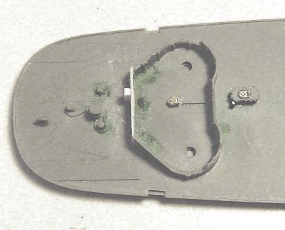
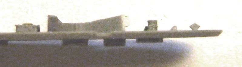
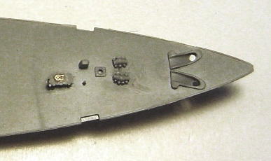
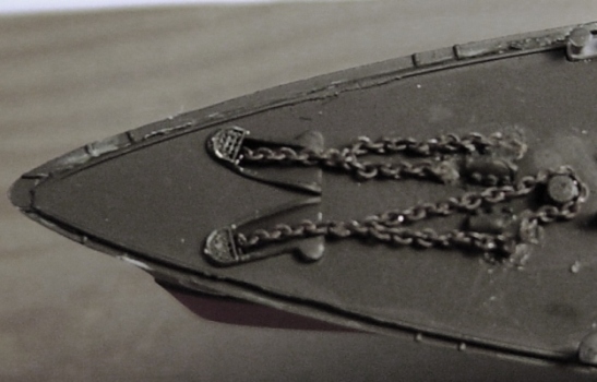
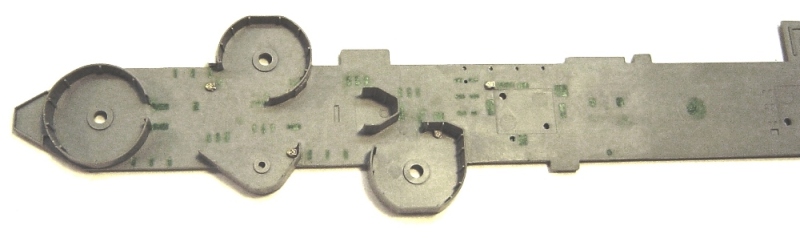
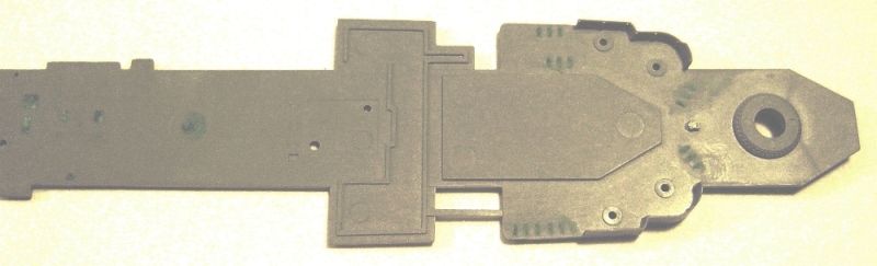
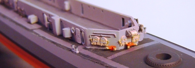

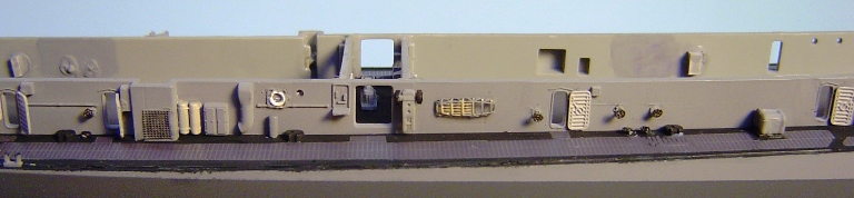
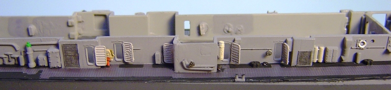
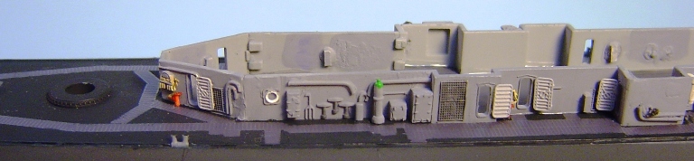
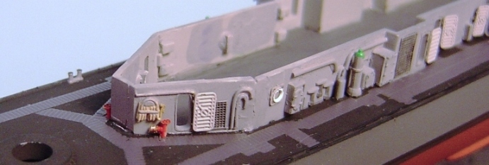
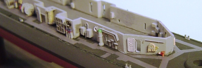
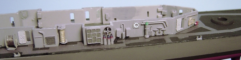
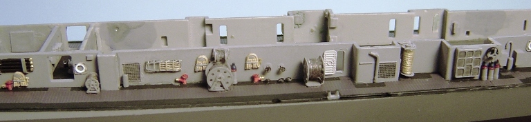
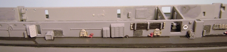
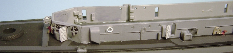
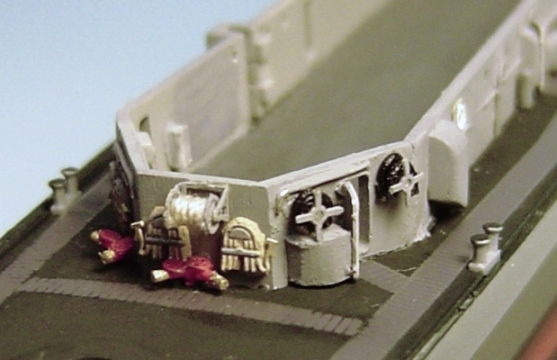
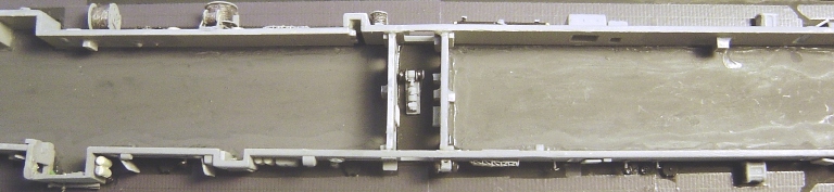
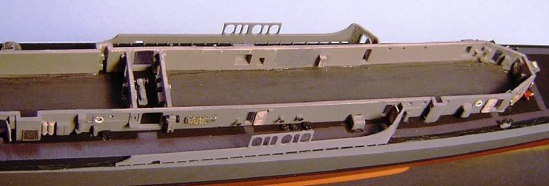
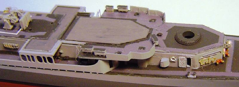
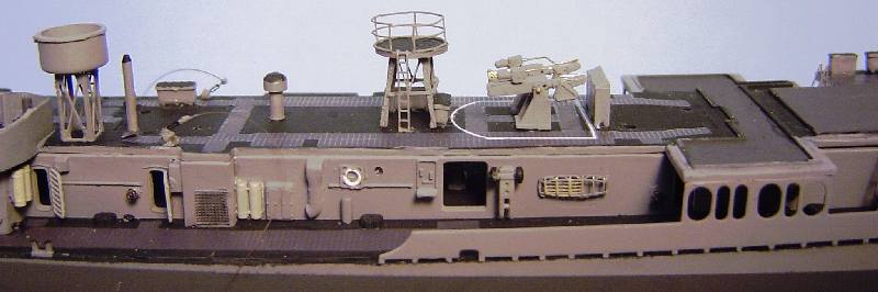
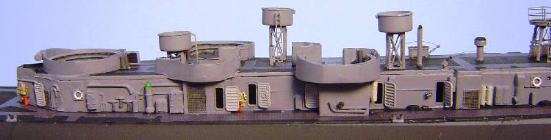
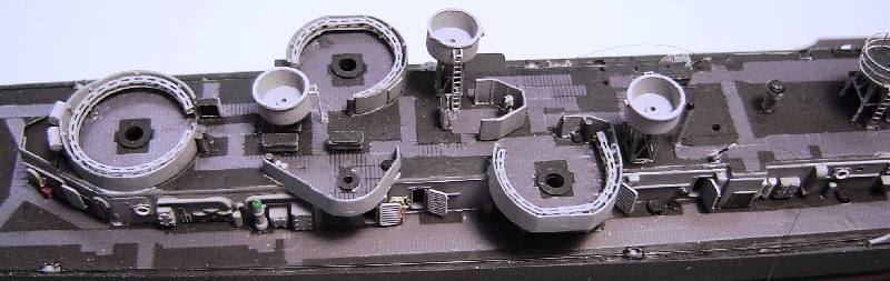
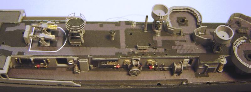
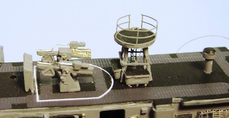
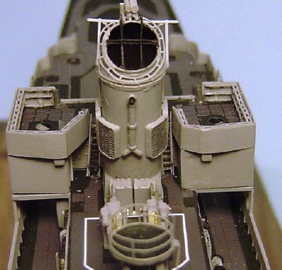
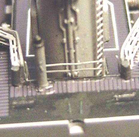
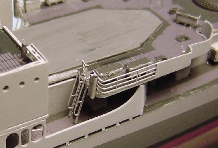
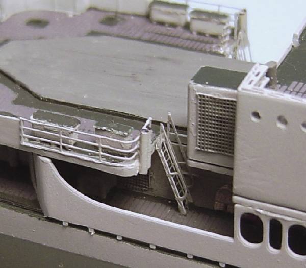
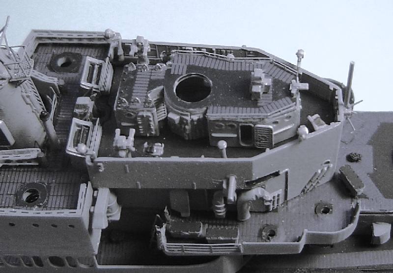
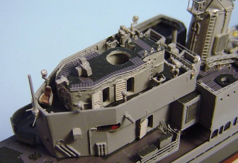
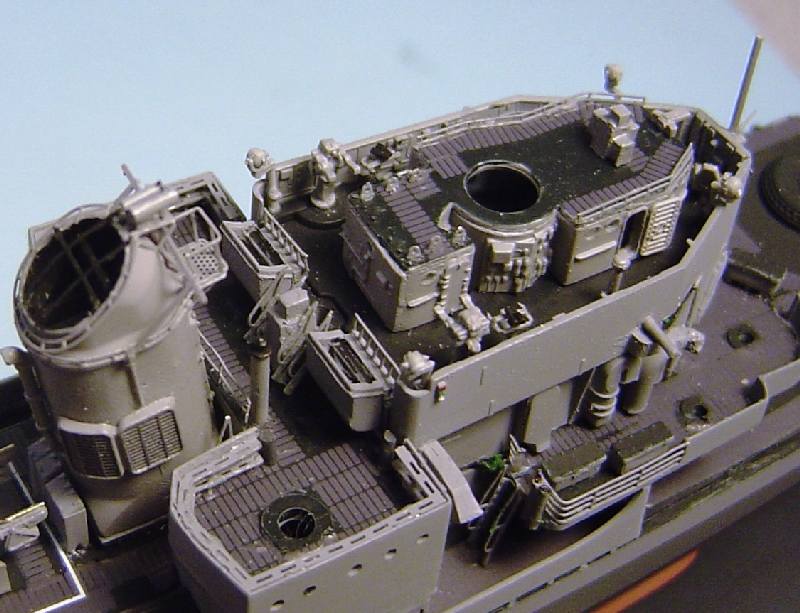
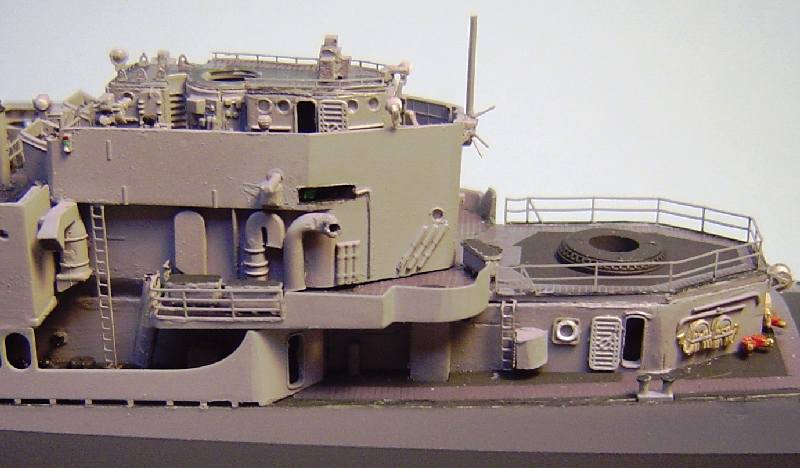
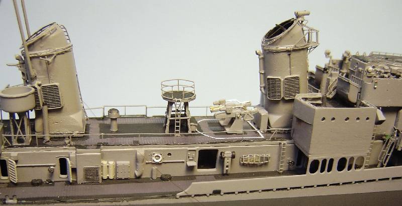
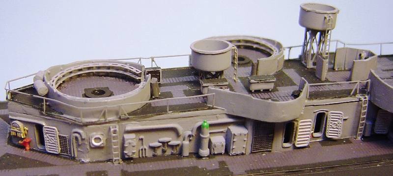
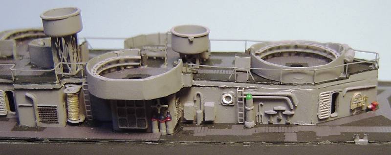
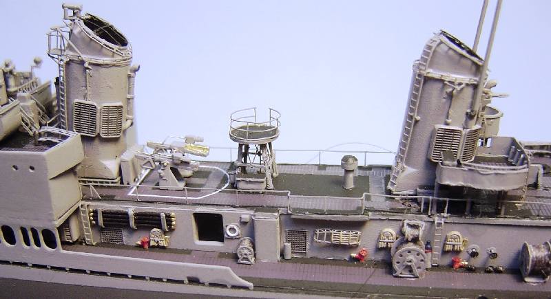
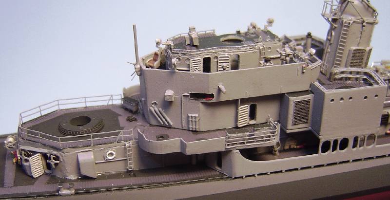
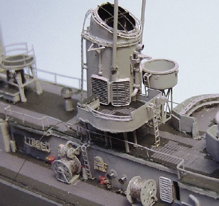
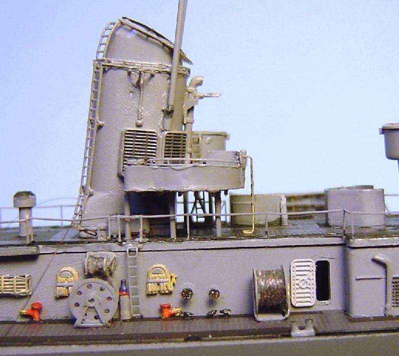
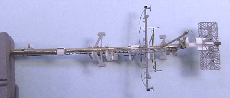
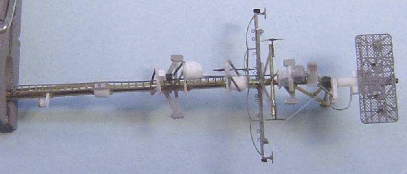
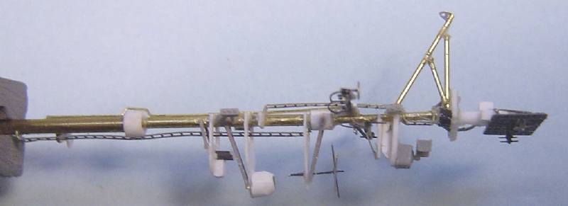
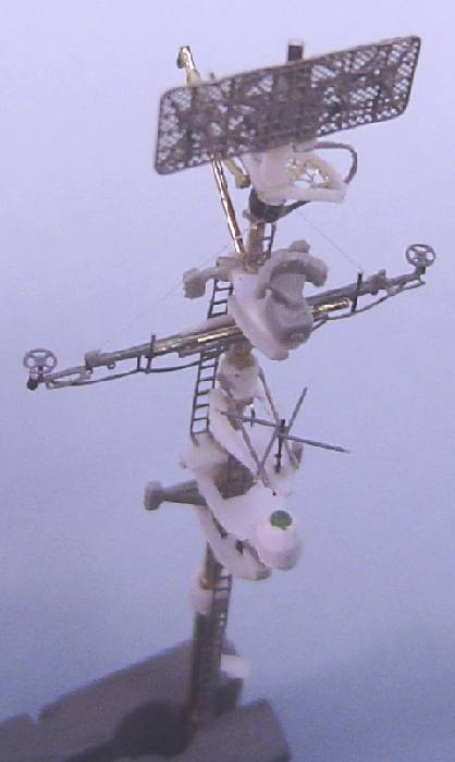
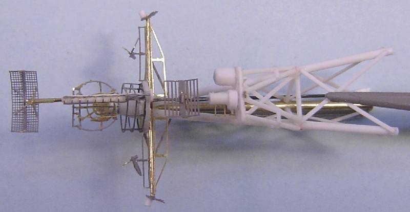
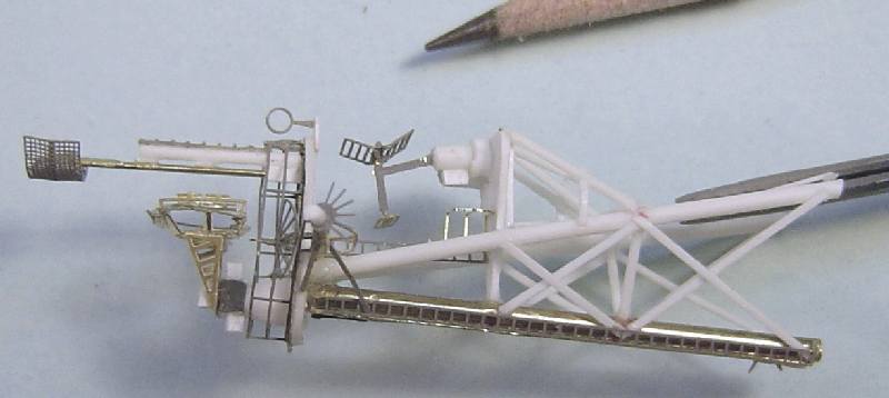
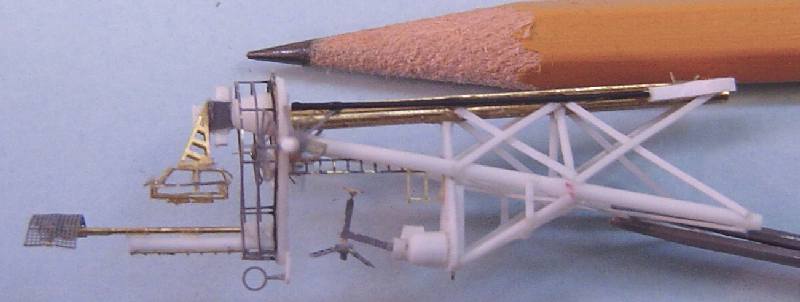
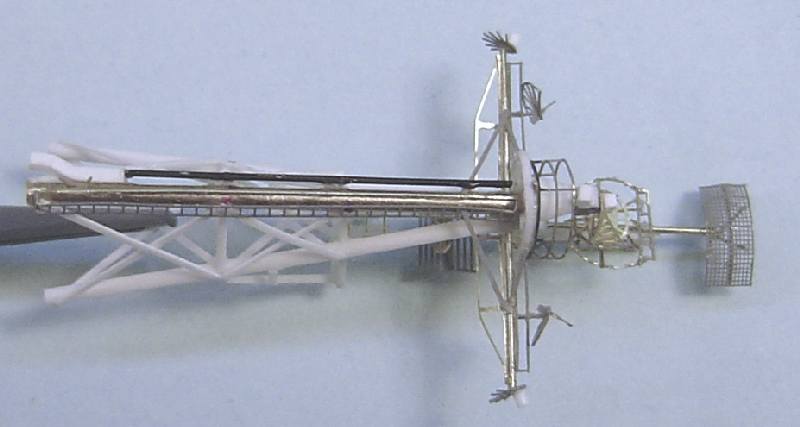
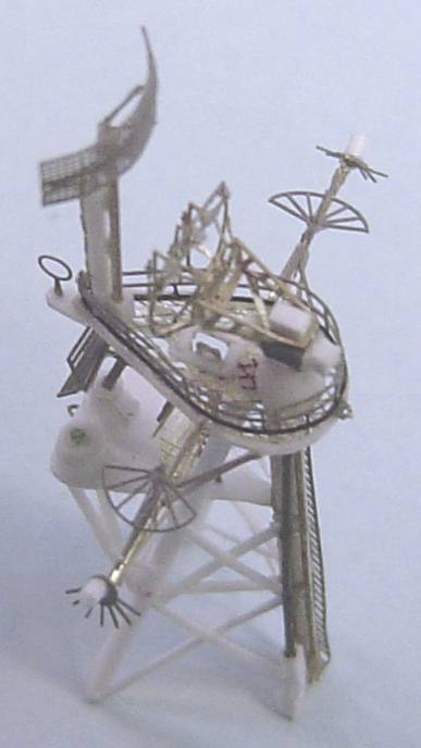
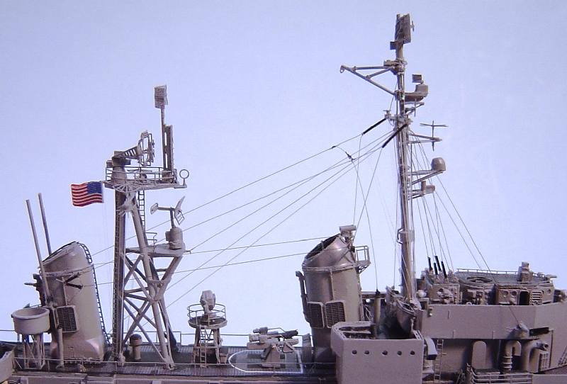
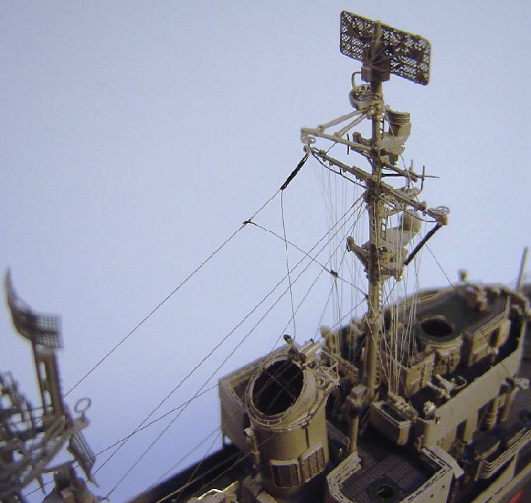
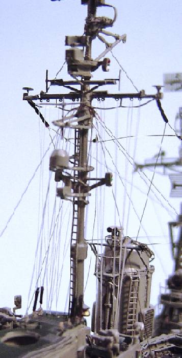
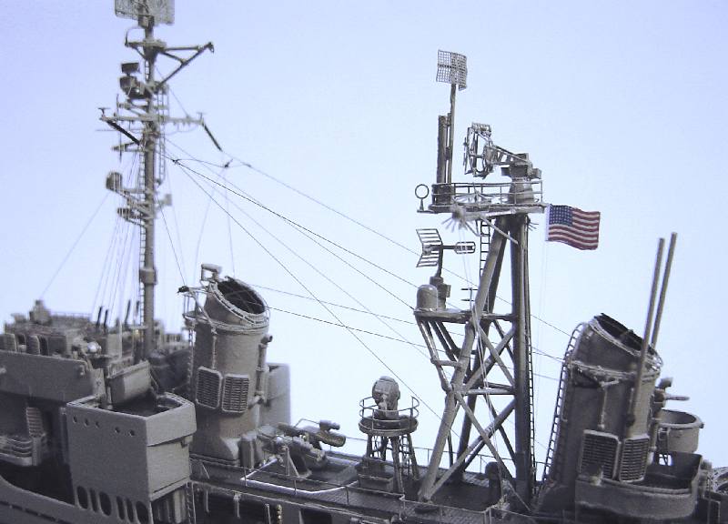
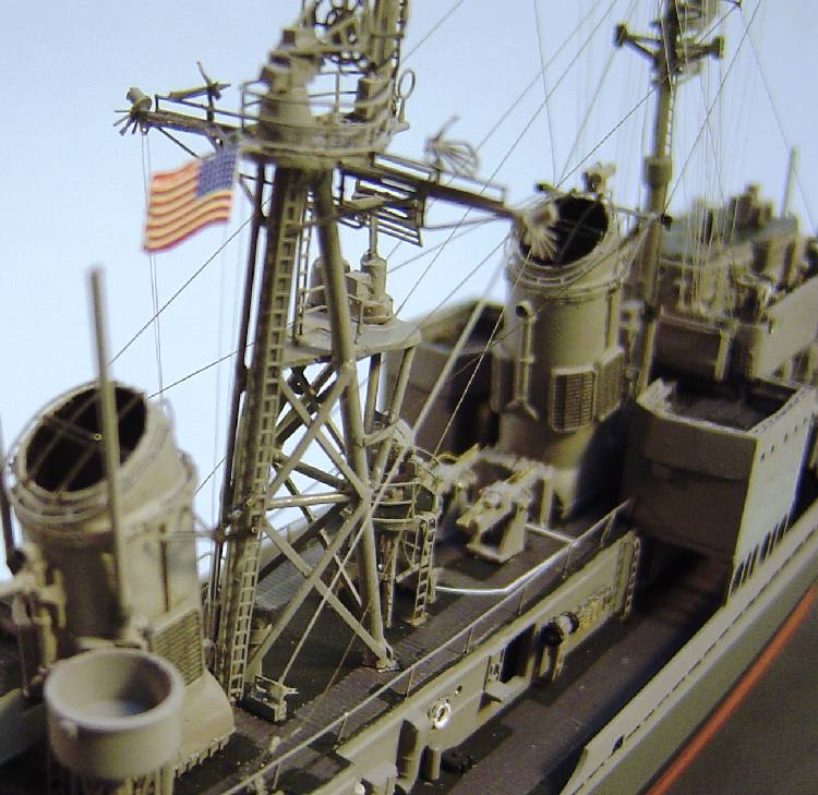
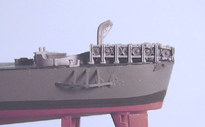
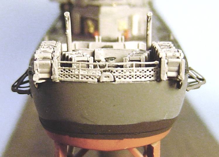

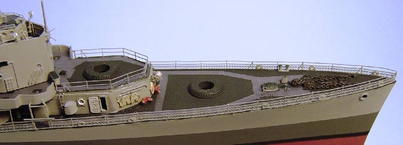
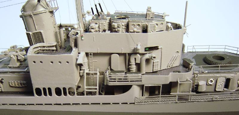
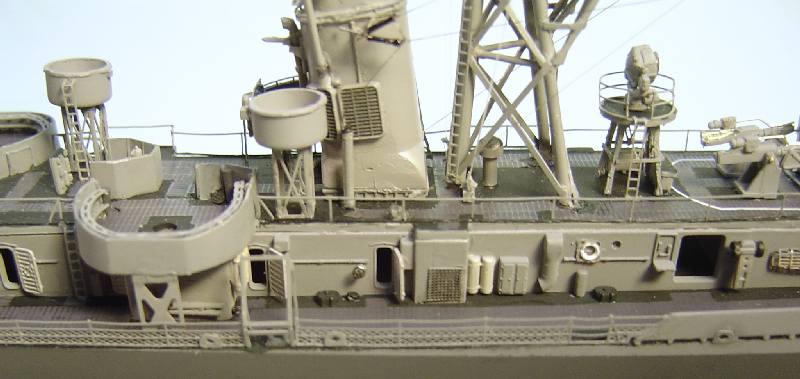
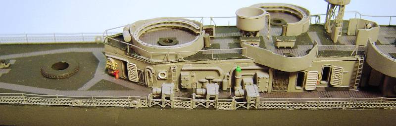
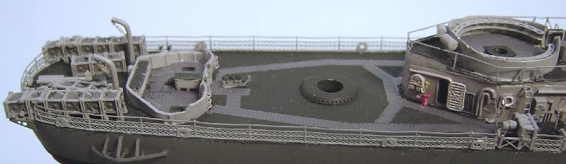
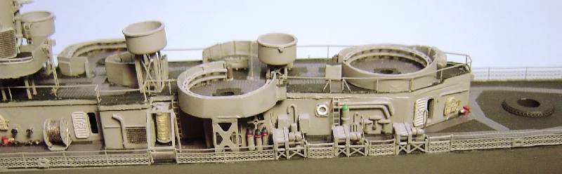
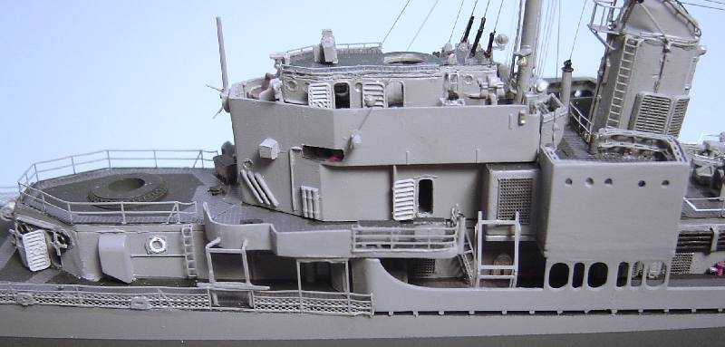
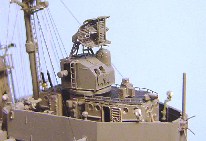
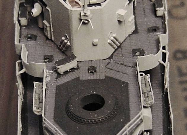
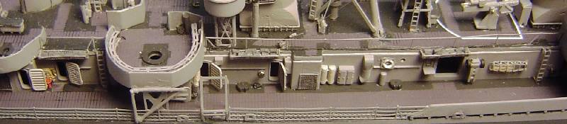
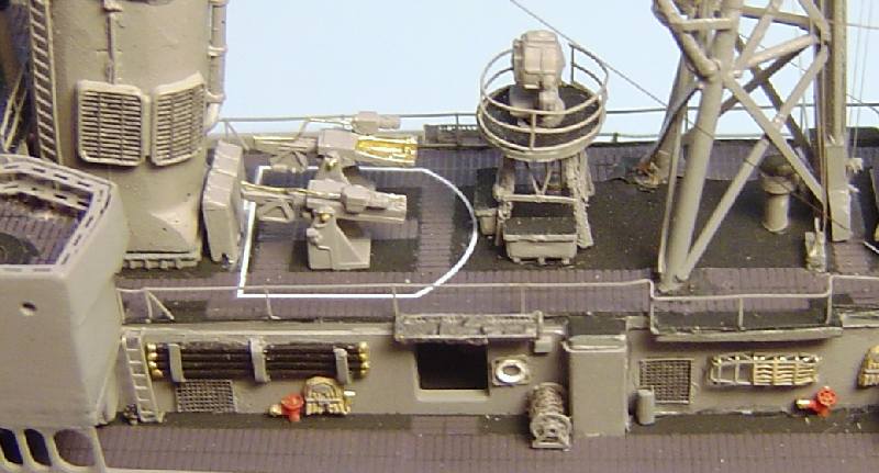
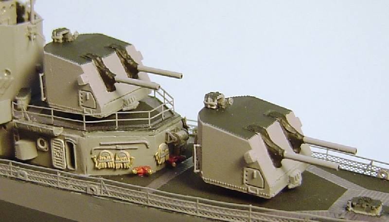
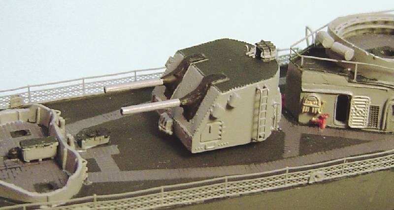
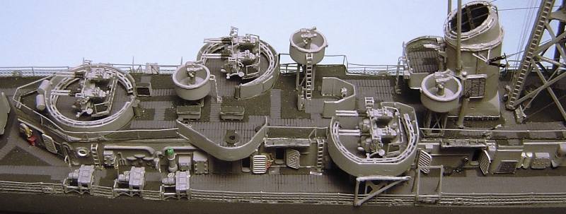
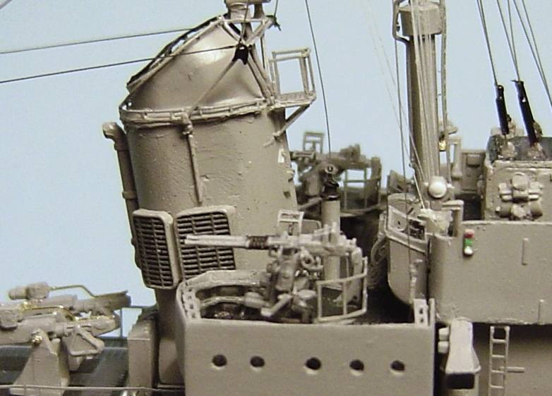
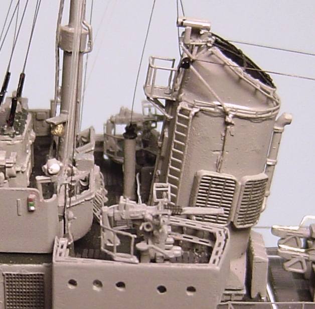
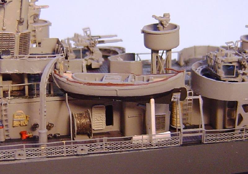
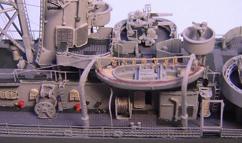
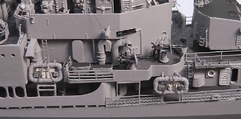
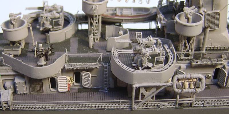
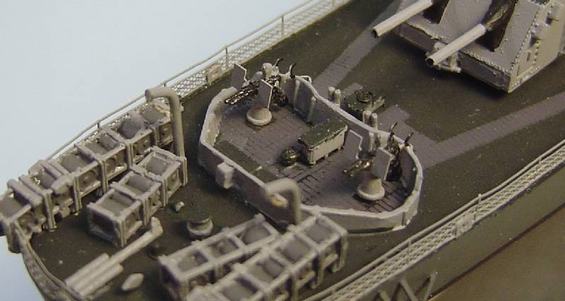
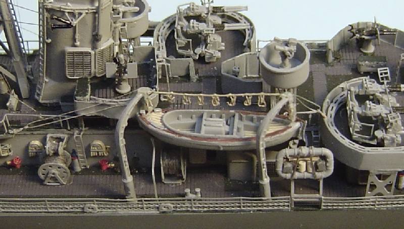
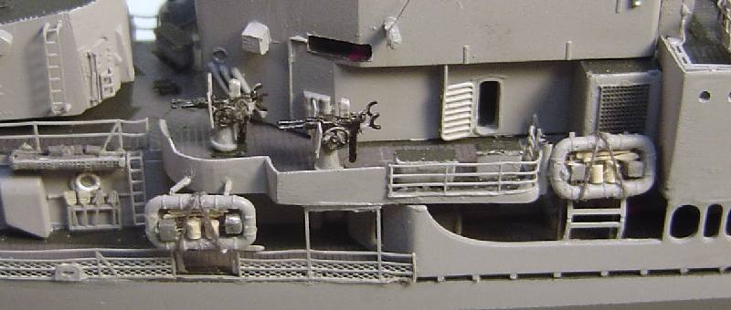
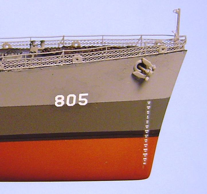
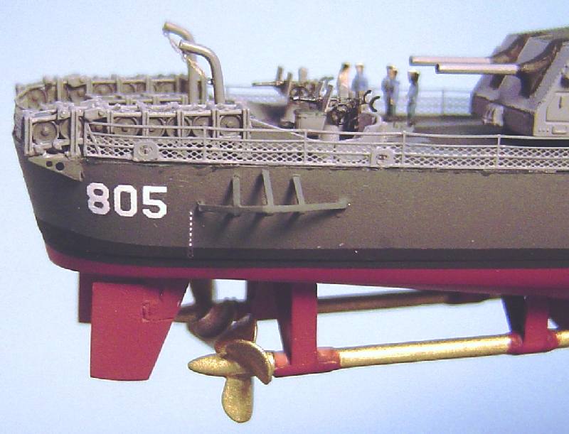

© ModelWarships.com