By Ed McDonald
photos by Ed McDonald
| THE KIT | ||||||||||||||||||||||||||||||||||||||||||||||||||||||||||||||||||||||||||||||||||||||||||||||||||||||||||||||||||||||||||||||||||||||||||||||||||
This ship was built from the Dragon Buchanan 1945 Tokyo Bay 1/350 Gleaves class kit. In 1945, except for painting, and a few other details, Buchanan and Lansdowne were nearly identical. I have no doubt that many other 1945 Gleaves class destroyers could also be built from this kit with little or no modification. Unfortunately, it seems that the Dragon Buchanan 1945 kit is, for the moment unavailable, or at the least in an as available mode. It was intended as a limited time offer when I bought it. Dragon should bring back the kit. Nevertheless, 98% of what I will be discussing applies equally to the 1942 Buchanan kit. There are few differences.
| ||||||||||||||||||||||||||||||||||||||||||||||||||||||||||||||||||||||||||||||||||||||||||||||||||||||||||||||||||||||||||||||||||||||||||||||||||
| GENERAL CONSIDERATIONS | ||||||||||||||||||||||||||||||||||||||||||||||||||||||||||||||||||||||||||||||||||||||||||||||||||||||||||||||||||||||||||||||||||||||||||||||||||
This build will require some skill. I have previously built Dragons 1942 Buchanan kit and photos of that build were selected by Dragon for use in their catalog. So, it seems that I do have some idea about what I speak. There is no question that this kit demonstrates a new state-of-the-art in plastic injection molding (slide molding, as it is called). You wont find any other plastic kit with as much detail. But, it also requires considerable patience. If you begin this build under the assumption that detail also means simplicity of build, you will be very disappointed, indeed. Quite the opposite is true. Extreme detail means extreme care and patience. Some of the parts are literally the size of a pin head. In addition to patience you will need the following tools:
Also, please note that I will NOT be assembling this model in the sequence suggested in the instructions. If you do so, things will most likely NOT fit properly! There are numerous errors, mistakes, traps and pitfalls hidden in the instructions (the worst part of this kit). For the 1945 Buchanan this is compounded by the fact that it does not have just one set of instructions. Rather, it has two. One is for the 1942 Buchanan and the second is for differences in the 1945 Buchanan. And, of course, the included Dragon photoetch and the highly recommended GMM Photoetch add two more sets of instructions that all need to be merged together in a workable sequence. This document will do that. Essentially, unlike the instructions, I will be building from the bottom-up-and-inside-out. That approach assures that things which otherwise might be difficult to access are done earlier. There is another major trouble with this kit. Several other kits that I have built suffer from a similar difficulty at times. So, it is not unique to Dragon. Specifically, parts seem to be molded in such a way that they will very tightly snap fit into other adjacent parts as if glue was not even required. Thats great if you dont intend to paint the parts before assembly. Unfortunately most of us take advantage of the parts differentiation and do paint before assembly. That process adds just a very small width to both parts perhaps no more than a combined 1/64 of an inch. But that is enough. In this kit the fit is so tight that after you have put together an entire assembly consisting of possibly 25% of the kit, you will be amazed and very annoyed to discover that it does not even come close to properly fitting the part to which it should attach! In this document I will point out those areas that REQUIRE some filing and sanding in order to assure that parts will fit together properly. Please pay attention to those comments. I will also be adding scratch built detail whenever applicable. This model will be detailed to the maximum possibility super detailed, as it is sometimes called. But, this is not required. Its just the way I model things when photos and resources are available. When I talk about scratch built details, feel free to consider them optional if you wish. Actually, there are far fewer scratch built items on my recent 1942 Buchanan build than I have had in many years. This kit is very good! But, its also surprisingly difficult and often frustrating!
| ||||||||||||||||||||||||||||||||||||||||||||||||||||||||||||||||||||||||||||||||||||||||||||||||||||||||||||||||||||||||||||||||||||||||||||||||||
| REQUIRED MATERIALS | ||||||||||||||||||||||||||||||||||||||||||||||||||||||||||||||||||||||||||||||||||||||||||||||||||||||||||||||||||||||||||||||||||||||||||||||||||
| ||||||||||||||||||||||||||||||||||||||||||||||||||||||||||||||||||||||||||||||||||||||||||||||||||||||||||||||||||||||||||||||||||||||||||||||||||
|
||||||||||||||||||||||||||||||||||||||||||||||||||||||||||||||||||||||||||||||||||||||||||||||||||||||||||||||||||||||||||||||||||||||||||||||||||
| OPTIONAL MATERIALS | ||||||||||||||||||||||||||||||||||||||||||||||||||||||||||||||||||||||||||||||||||||||||||||||||||||||||||||||||||||||||||||||||||||||||||||||||||
| ||||||||||||||||||||||||||||||||||||||||||||||||||||||||||||||||||||||||||||||||||||||||||||||||||||||||||||||||||||||||||||||||||||||||||||||||||
|
||||||||||||||||||||||||||||||||||||||||||||||||||||||||||||||||||||||||||||||||||||||||||||||||||||||||||||||||||||||||||||||||||||||||||||||||||
| THE MODELED FOR DATE | ||||||||||||||||||||||||||||||||||||||||||||||||||||||||||||||||||||||||||||||||||||||||||||||||||||||||||||||||||||||||||||||||||||||||||||||||||
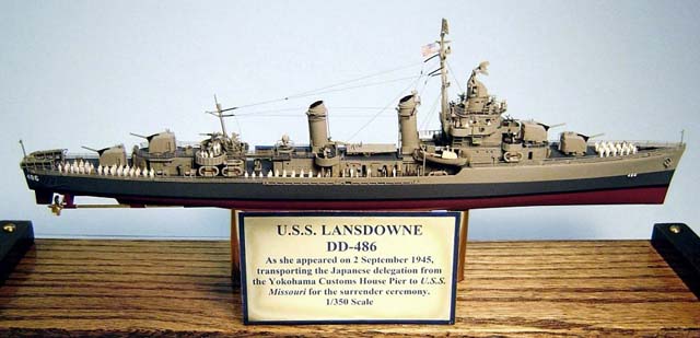
This model will be designed to represent Lansdowne as she appeared on the morning of 2 September 1945 in Tokyo Bay where she transported the Japanese delegation from the Yokohama Customs House Pier to USS Missouri for the Japanese surrender ceremony. There are several photos of Lansdowne on that day. 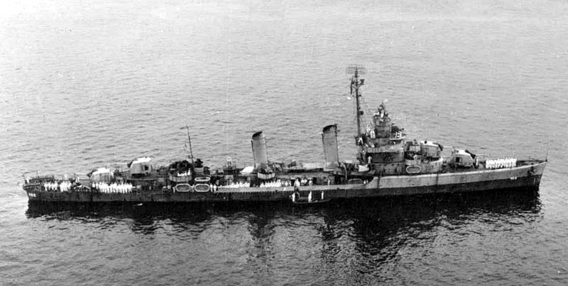 Photo: Navsource.org Additional information and photos may be found at DANFS History, NavSource Photo Archives and at the USS Lansdowne Home Page.
STEP 1 - THE HULL |
This is the lower half of step 6 in the instructions. Build the hull, shafts, struts and rudder as instructed. Lansdowne was painted in the attractive MS-22. Buchanan in the same period was painted in the gloomy MS-21; which is the primary reason that I chose to portray Lansdowne rather than Buchanan. Ill say this now and not repeat it over and over again later. MS-22 was a simple and obvious camouflage. The hull was Navy Blue (5-N) from the boot top (waterline) up to the shear line (a straight line extending from the lowest point on the main deck forward to the bow). Above that, the hull was Haze Gray (5-H). Above the main deck the superstructure was simple. ALL horizontal surfaces (including the tops of vents, hatches and everything) were painted Deck Blue (20-B) and ALL vertical surfaces (no matter how small) were painted Haze Gray (5-H). Your first test will be the removal from the sprues and file clean-up of the screw shafts and struts without breaking or damaging them. Get out those sharp tools and blades, be careful and file cautiously to remove any remnants of the sprues; which on this model always seem to be in the very most visible or difficult spot! This is also a chance for you to sharpen your skills at shaving with an Xacto blade. If you got through this well enough good work. But, it will get MUCH more difficult before you are done. Add the shafts (caution there are port and starboard versions) and rudder to the hull, putty as required and do any preparation work you might desire for the purposes of mounting the ship to its eventual base. I drilled holes in the lower hull for mounting bolts. Once the upper and lower hulls are assembled, such work will be impossible. If you are using the mounts supplied with the kit, you can ignore this step. But, I prefer something a bit more solid that allows for a possible future change of base. Paint the entire lower hull Hull Red and then add the mounting bolts, thus avoiding painting the threads of the mounting bolts. Firmly glue the mounting bolts, or whatever mounting means you choose, in place. 1945 Version - By 1945 the portholes on the forward upper hull had been totally removed. Photos of the period show no indication whatsoever that they ever existed. So, for a 1945 version, fill them with putty and sand smooth. 1942 Version - In 1942 the portholes did exist on some early Gleaves destroyers. In that case you may wish to drill them through. Additionally, I am going to choose to add the amidships spray shields (parts A21 port and A36 starboard) to the upper hull at this time. Usually, these are added late in a project (as the instructions suggest in step 9 along with the main deck railings. But, my experience is that they are VERY difficult to properly add at that time. There is just too much other stuff in the way. Plus, by adding them now, its possible to sand them smooth with the outer edge of the hull and putty the gap along their forward edges. As before, you should be very careful removing them from the sprues and filing the attachment points. They are also likely to be a bit warped, which may require a little heat and bending to correct. Attach them to the outboard edges of the upper hull and make certain there is no conflict with the installation of the aft main deck part. Putty and sand the gaps as required. But, keep the drainage ducts open.
Now glue the upper and lower hulls together, putty and sand as required. In two attempts I have not achieved a perfect fit and some putty/sanding will probably be required. And, that sanding of the hull parts gap will no doubt require some touch-up painting of the Hull Red. Normally, I would paint the water line last. But in this case, the existence of screw guards makes it impossible to mask the water line later after they are added. So, Ill mask and paint it now, then add the screw guards and paint the upper hull. Im going to spend a few minutes talking about the screw guards; which are one of the more frustrating parts of the kit. Step 7 of the instructions only poorly shows their proper installation. Take a look at the box art and the painting drawings. First, in the raw photoetch state there is no difference between the port and starboard versions. Both are part MA5. But, after bending, there is a difference. Thus, two bending jigs (parts D1 and D2) are thoughtfully provided one for port and one for starboard. BUT, they are not really parts D1 and D2. Actually they are parts F1 and F2! The instructions are wrong. Welcome to the USS Buchanan by Dragon. Well, forget that and just pay attention to the mentioned drawings. For correct installation, the bottom support shafts are perpendicular to the hull side and the upper shafts angle. Also, the longer outside shaft is forward and the shorter aft. Its pretty clear if you check the mentioned drawings. The jigs are provided and I strongly recommend using them. But, they are not the entire solution. No matter how hard Ive tried, they just do not create bent screw guards that fit correctly. Well, its very difficult to bend something such that eight different points simultaneously contact a curving surface! You also have a choice of which to use the thinner (and more bendable) GMM screw guards or the thicker (and stronger) Dragon ones. I used the Dragon ones on my last build of this kit and spent about an hour each trying to get them to fit smartly. This time I used the GMM ones. They fit correctly in the bending jigs and seem to bend just fine. But, alas, the fit problems are the same. After a couple of hours I came to the same conclusion as last time. To wit the jig is not the whole answer. It helps and you should do the best you can with it. But, be prepared to hold each leg in place one by one for as long as it takes to get these things to fit properly. In the past, Ive hand bent dozens of screw guards without benefit of a bending jig that fit just fine. I really dont understand why these are so difficult to work with. Could it be a less than correct bending jig? Nevertheless, when you get the screw guards properly attached to the hull (and eventually you probably will) you should brush paint their insides. Airbrush spray has a hard time reaching those spots. Once the glue and paint are dry, its time to paint the upper hull Navy Blue (5-N) Almost last, for this MS-22 build, the upper hull above the shear line forward is painted Haze Gray (5-H). This is also an appropriate time to spray part B10 (step 5) Haze Gray (or whatever depending on your choice of camouflage) after adding the two PE doors. Well be adding B10 soon. Part B10 is another confusing part due to a VERY misleading step 5 illustration. But that comes later. Last, the screw shafts should be painted Gloss Brass. I cant say with 100% certainty that this was the case for Lansdowne in 1945. But, it does seem to be the case for all destroyers where photos of the shafts exist. 1942 or 1945 Buchanan As mentioned, the painting described above is for Lansdowne in 1945 (MS-22). For 1945 Buchanan, MS-21 should be used. For a 1942 version of Buchanan, her complex and very attractive MS-12 (some sources refer to it as a highly unusually MS-16) should be used. There were also several Gleaves class ships that spent some time in various MS-32 patterns. The choice of painting depends on your choice of ship and date. 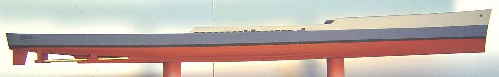 Mounted, assembled and painted hull
STEP 2 - THE MAIN DECK |
The primary effort in this step will be to get the decks painted Deck Blue and prepared for addition to the hull. So first we want to add all detail to the decks that will be painted that color. Referring to step 2H (forward deck) in the instructions, lets add the chain locker covers parts A46 and A47. Once again, the instructions are just a bit unclear about their orientation. The bend in these parts should point outboard. This may be your first attempt to deal with very small plastic parts. Treat them as you would photoetch parts. In order to avoid a lengthy search for spronged parts, instead of removing the parts from the sprue, remove the sprue from the part. As far as the forward deck is concerned, all other parts will be painted Haze Gray and thus, added later. OPTIONAL DETAIL - An exception is the forward deck hatch part A22 (and as mentioned below the aft deck hatch - part A32). This ship is being modeled in a peace time mode at the occasion of the Japanese surrender. It would have been in condition X-Ray (relaxed defense). From all I can determine, in that condition, the deck hatches (forward and aft) would have been open. So, instead of adding part A22 to the forward deck, I have chosen to open (drill, cut and file) the forward hatch and cut and add a small brass coaming around that hatch. The several other features associated with this open hatch, being other colors, will be added later. Additionally, I have added a GMM PE generic hatch somewhat aft in front of the forward deck house. 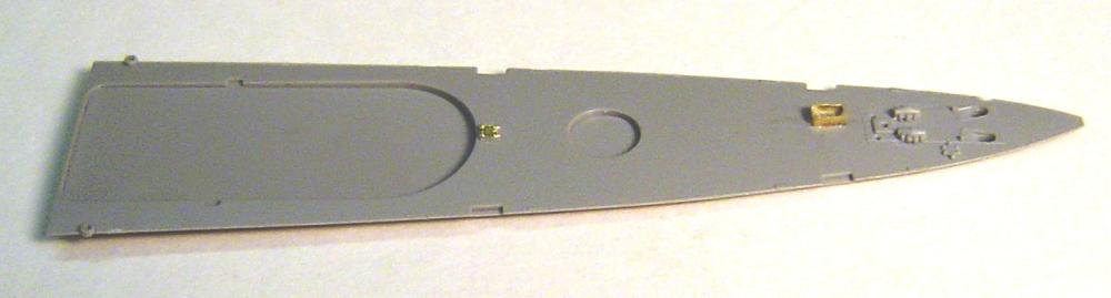 Forward deck ready for painting The construction of the aft deck is shown in step 5 of the instructions. DOT NOT add part B10 at this time. If you do, its unlikely that things will fit properly. In fact, part A32 (after deck hatch) is the only item to add now before painting the deck. Ill be opening the hatch and adding a coaming just like on the forward deck. Ill also add a GMM generic scuttle aft of that hatch. Troubles with the K-guns. Neither Lansdowne nor Buchanan every received the late war 2 rack K-guns. They ended the war with the mid-war single rack version. But, Dragon did not remold the aft deck for their 1945 version and the mounting holes are there for the multi-part 1942 early war K-guns. That means there are a lot more holes than needed. There is one other attendant issue. By 1945 the forward most of the three K-gun units on each side had been removed. In fact, the 1945 kit only provides four mid war design K-gun parts (unlike the six early war that existed in 1942). But thats rather moot since we will be using the GMM photoetch K-gun rack and gun assembly and davits and therefore there is no need for any mounting holes at all except perhaps for the davits (which I will drill later as required). So, after that long winded explanation, putty fill all of the K-gun mounting holes before painting. 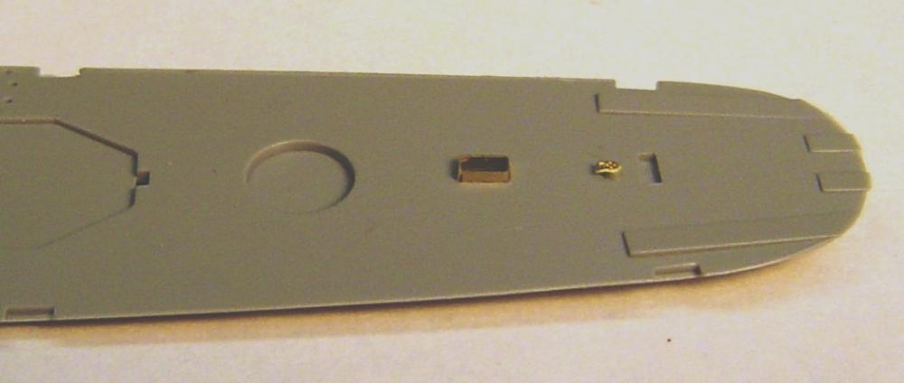 Aft deck ready for painting Now is the time to paint the decks Deck Blue (20-B). At this time Im also going to pre-paint many parts Haze Gray (5-H). That will include several sprues of plastic parts and all photoetch parts (Dragon and GMM). So, in the future, you will see very little unpainted shiny brass in the photos of this build. There are still quite a few things to be done to the deck parts before their addition to the hull. Ill discuss these individually. Generally speaking, the order in which they are accomplished does not seem to matter much, although the order described below did work for me.
|
|
STEP 3 - DECK HOUSE BASIC ASSEMBLY AND TEST FITTING |
There are three deckhouses. The purpose of this step is to accomplish the basic first level assembly of each deckhouse and to assure that they properly fit the decks. Forward Deck House OPTIONAL DETAIL I chose to open all portholes (with an appropriately sized drill bit) and all doors of this level. The usually difficult task of opening doors is one of the easiest things to do on this kit. The designers included an extra depth of plastic behind each door. To open a door, simply file it off. Presto you have a perfectly shaped open door. All models should include this feature. Additionally, I filed down and flattened the molded-in fire hose reel on part A14, which I will replace with a higher detail GMM generic PE file hose reel. Thats all we need now for the forward deckhouse. And, if you are like me (twice in a row on two consecutive builds) you will now discover that the forward deckhouse is a VERY tight fit on the forward deck. Its a hard pressure snap fit. Its so tight in fact that the very idea of snapping it into place after all the tiny detail has been added is, in fact, a very scary scenario. You want high detail very fragile assemblies to simply slip into place like butter on a baked potato. So, file the aft end and corners of the deckhouse assembly and the deck itself until it does simply slip into place. Amidships Deckhouse OPTIONAL DETAIL As before, I have chosen to open several doors and drill out all portholes. The amidships deckhouse to deck fit is a very tight snap fit. It will become much worse (perhaps impossible) once the parts are painted and the deck and part B10 bulkhead are assembled. I cant over emphasize the importance of filing and tuning the fit of these parts now so that they slide together with no difficulty at all. After Deckhouse OPTIONAL DETAIL Once again, I opened several doors and drilled out all portholes. I also filed off three molded in vertical ladders and one bulkhead mounted cable reel; which will be replaced with PE items. The fit is a lot like the forward deckhouse a very tight snap fit under considerable pressure. Filing is needed in several places now or you may be very disappointed later.
STEP 4 - ADD THE MAIN DECK TO THE HULL |
Unlike the instruction sequence, now that we know that all parts that are going to be added to the decks fit well enough, Ill go ahead and add the decks to the hull. First add part B10 (instructions step 5), the main deck forward bulkhead. But DO NOT attempt to add it to the aft deck first (as the instructions indicate) and then both parts to the hull. Odds are that it will not fit correctly. Instead, add part B10 to the hull assembly. It slips very neatly down into a slot at the forward end of the aft deck. Dry fit and test first (with decks added) so that you understand how to position it. Its really quite simple. Then glue it in place. If you have chosen to open the deck hatches, now is the time to glue the aft inclined ladder in place on the aft deck. All hatches (and doors) hinge on the forward side. So ladders incline aft (forward on the bottom, aft on the top). These ladders must be taken from a generic GMM ladder set. The ladders included in the specialized GMM set are too wide, and youll need them later anyway. Test fit the deck to make sure the ladder doesnt interfere with its placement. Glue the aft deck in place. Be sure to add glue to the arching cross-ribs since the deck should arch outward for water run-off. Last, glue the forward deck in place. The aft end of this deck should align perfectly with the top of part B10 and the bow end should fit neatly into place on the hull. 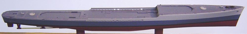 Assembled and painted hull and main deck
STEP 5 - THE AMIDSHIPS DECKHOUSE - 1 level bulkheads and 01 deck |
From now on, with very few exceptions, the assembly sequence will be bottom up and inside out. So, lets start with the amidships deckhouse. Its the lowest and most inside thing that remains. NOTE: See step 22 NOW for a late correction to the location of the catwalk between the amidships and aft deckhouses. The basic first level of the three deckhouses were already built in step 3. But, there is some room for putty and some filing to eliminate gaps on all three deckhouses. Do that now. The process now will be quite similar for all three deckhouses. Their tops should be painted Deck Blue and their sides Haze Gray. But first, add all parts to both the tops and sides that should also be painted those same colors. For the amidships deckhouse refer to step 3 of the 1942 instructions and add part A6 to the top and all doors that were not opened to the sides. I also OPTIONALLY added GMM generic scuttles to the two hatches on top. All other parts mentioned in step 3, for various reasons, should be added later. 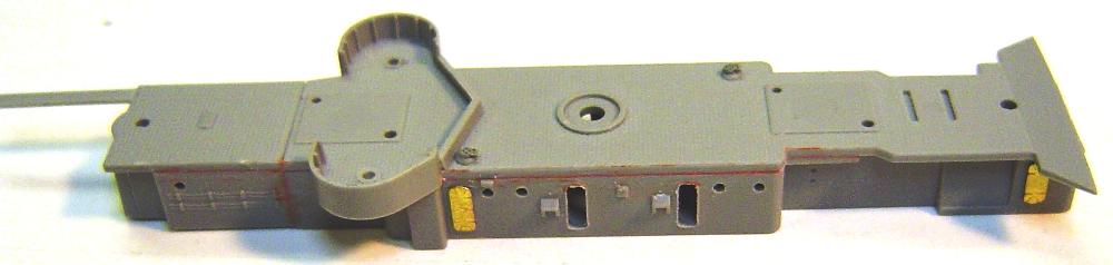 Amidships deckhouse ready to paint Now is the time to paint the top Deck Blue, mask over it and paint the sides Haze Gray. Also paint the undersides of all overhanging platforms and catwalks Haze Gray. Now well add the remaining detail parts to the deckhouse. But some should not be added until AFTER the deckhouse is attached to the deck. Those that can be added now are:
Now that everything lines up perfectly, add the amidships deckhouse to the deck. Be certain to push the deckhouse as far forward as possible, snapping its forward end into the slot on part B10. The forward edge of the deckhouse should fit snuggly with the forward 01 deck with no gap and the 20mm tub support posts should be vertical and properly inserted into their holes on the deck. If that is not the case try again. Next well add the rest of the amidships detail to the main deck:
Im going to continue with the bottom-up assembly plan and delay the addition of the more fragile guns, searchlight platform, torpedo crane and other 01 level detail until after all the main deck deckhouses and detail has been dealt with.
STEP 6 - THE AFTER DECKHOUSE - 1 level bulkheads and 01 deck |
Just like the amidships deckhouse, add the parts on the tops and sides that will be painted either Deck Blue or Haze Gray. Refer to step 4 of the 1945 instructions. Since I opened all doors and no other parts are applicable at this time, the only part I added was an OPTIONAL GMM generic scuttle on the hatch on the top. 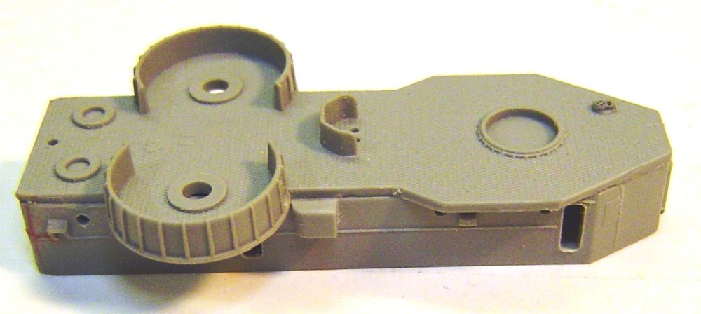 Aft deckhouse ready to paint Paint the deckhouse top Deck Blue and the sides and overhangs Haze Gray. Now, before adding it to the deck, lets add some of the detail:
 Aft Mk51 platforms
 5 inch practice loader Now, finally, add the deckhouse. It seems to work best if you slip the aft end into place, push aft and snap the forward end down. A touch of glue should be added to the aft end of the catwalk. There are only a couple of things to add to the deck near this deckhouse
Im going to wait and add the K-guns and depth charge racks in coordination with the main deck rails.
STEP 7 - OTHER 1 AND 01 LEVEL DECK DETAIL AFT OF FORWARD DECKHOUSE |
Of course, there is considerable detail to still be added to the stern, but that can be done at any time. The same is true for the bow. The K-guns and racks need to be coordinated with the main deck rails and will, therefore, come later. But there are quite a few items to be added in the 1 deck and 01 deck level aft of the forward deckhouse. My experience is that attempting to add them after the forward deck house has been added can be much more difficult due to limited accessibility.
|
IMPORTANT CORRECTION NOTE: The next step 4 does appear to be accurate for Buchanan in 1945, and Im sure many other ships. However, as it turns out after later study of photos of this area of Lansdowne, it is not accurate for that ship. Lansdowne had a different railing configuration aft of the inclined ladders. For your ship youll need to decide between continuing with this step four or skipping to the somewhat OPTIONAL step 5 below. You should read step 4 in any event.
|
Note: See photos in step 15 and beyond for correct Lansdowne amidships deckhouse forward rails.
STEP 8 - FORWARD DECKHOUSE LOWER LEVEL - 01 level bulkheads and 02 level deck |
Just like the other deckhouses, add the parts on the tops and sides that will be painted Deck Blue or Haze Gray. Refer to step 1 of the 1942 instructions. If, like me, you opened all doors, then the only part to be added is MA13 (the 1945 20mm gun platform) without its shields (MA33), which will be added later. 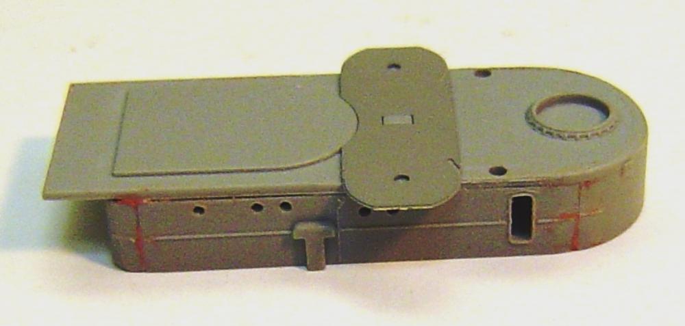 Forward deckhouse (1945 version) ready to paint Paint the deckhouse top Deck Blue and the sides and overhangs Haze Gray. Hint: For all of these forward deckhouse levels 1) set it on its bottom, paint the top Deck Blue and dont worry about spillover on the sides 2) set it on its top and paint everything that can be seen Haze Gray. This assumes you are using an airbrush; which you really should be using. Now well complete the detail on this deckhouse assembly as follows:
Additional detail will be postponed for just a while. 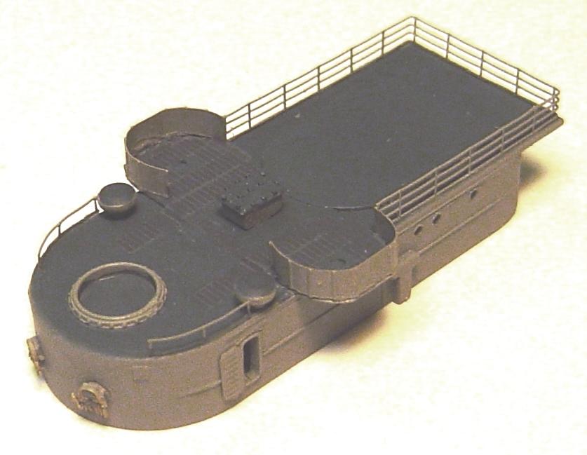 Completed forward 1st level deckhouse ready to install
STEP 9 - FORWARD DECKHOUSE 2nd LEVEL 02 level bulkheads and 03 level deck |
This is just a bit confusing due to rather sketchy instructions and one clear cut design mistake. The instructions for the 1942 build are complete and the assembled unit does fit properly. But that is not the case for the 1945 build. Refer to step 1 of the 1945 instructions, and if confused, the 1942 instructions may help. Assemble parts A9, A19, A18 and A20, being careful about port and starboard sides and left/right arrangement of part A20. The trouble is that these are actually parts designed for the 1942 version, for which part MA13 (20mm gun platform) is not used. This assumes that MA13 has zero thickness; which is obviously not the case. Unless you want this level to sit unevenly on the forward deckhouse, you will need to test fit this assembly, mark the edges of part MA13 and file off about 1/32 of the forward part of the bottom of this assembly (from part A9). Its not all that difficult if you mark the positions well and have a good miniature flat file. Ill also add part P9 (for the 1945 version) at this time so that a nicely painted top deck is possible. OPTIONAL - I chose to drill out all portholes and open the port door on part A20. You may also wish to do some putty fill in a few places. The only other details to be added at this time are any doors that you chose not to open.
Now paint the top Deck Blue and the sides Haze Gray. And, as always, there is some detail to be added:
All other detail, which is quite a bit, will be postponed until after the wing bridge shields have been added; which will be done in coordination with the combining of this level and the one above it.
STEP 10 - PILOT HOUSE (BRIDGE) - 03 level bulkheads and 04 level deck |
Refer to the 1945 instructions inset D and combine parts P2, A15, A16 and A17. The mentioned instructions fail to identify parts A15, A16 and A17. Refer to the 1942 instructions for those part numbers. This assembly does seem to fit well enough to the assembly below with no troubles. But it is different. Dont try to get it to fit INSIDE the cutout shape on the deck. Unlike all other deckhouses it overlaps forward and aft and only its sides fit inside the cutout. For proper fit, its quite important that the bottom edges of its bulkheads be smooth and flat. OPTIONAL Im going to drill out all portholes. This assembly is provided with two doors already opened and one closed. That does seem to be normal non-combat and fair weather status. So, I opened no doors OPTIONAL I filed off a molded in ladder on the aft end of the assembly, which I will replace later with a PE one. This is one of the most visible parts on the finished ship, so I do recommend some filing and putty work to get the seams really smooth. Any closed doors should be added now. In my case thats one MB3 type door aft on the portside. SORT OF OPTIONAL - There is one other item that I am going to add now. Soon well be laying out a complete plot for the rigging. Of course rigging is, to some extent, OPTIONAL. However, it is also very important and perhaps more than anything else distinguishes a good model from an amateurish one. From experience with several destroyers and this kits 1942 version I know that there will be a need for two stays (fixed ropes (wire cables)) running forward from the mast to the outside of this level. Drawings often show these stays attaching inside the canvas covered rails that will soon surround this assemblys deck. But, I know that is wrong. And that if stays had been attached like that (I tried it once) the Mk37 radar would not have been able to turn fully to the side. Further, there is a good 1943 photo of Lansdowne (and other ships) that shows the mentioned stays clearly attaching outside the rails. In fact, if you notice that small little bump on the mid starboard side of this assembly, thats where the stays attached. Only it was not a little bump. It was a post that extended a few feet outboard of the bulkhead in order that the stay could clear the Mk37 and the railings. I assure you, there will be no easier time than now to add those posts. If you would like to continue with this and if you wish to add these stays, then I can suggest no alternative other than to continue reading. I used .025 styrene rod for the post and knowing that there will eventually be some tension placed on these items, I drilled holes for the posts on each side (above the aft door on the port side). The rod was cut to a length of 4/32 with 3/32 extending outboard on each side; which is just a bit more than enough to do the trick. I also glued a bit of stiff steel wire on each side to add some additional strength to the styrene posts.  Pilot House ready to paint Now, as always, paint the top Deck Blue and the sides Haze Gray. Then, well do the detail. There is a lot of detail on this level. But, due to its fragility, much will be postponed until after the complete forward deckhouse unit is assembled. For now, Ill add the following:
Thats all for this assembly at this time.
STEP 11 - INSTALL THE FORWARD DECKHOUSE FIRST LEVEL |
Addition of this deckhouse requires a few relatively simultaneously assembled items.
STEP 12 - INSTALLATION OF THE BITS & MAIN DECK BOW RAILINGS FORWARD |
Before moving on to the remainder of the forward deckhouse, I want to add the forward deck railings. Actually, I would rather not at this time, but it seems I have little choice. The difficulty is that from test fitting and prior experience I know that the GMM bow railings only extend as far aft as the forward boat davits. That leaves a small one inch gap between the end of those rails and the 1 deck to 01 deck inclined ladders. There are multiple-bend railings in that area and they will certainly be considerably more difficult to add after the upper deckhouse levels have been added. But before I can add any main deck railings, I must add the bits (parts C3). We avoided those earlier because the instructions which suggest adding them to the deck before the deck is added to the hull just do not work. I did that on my first build of this kit and was forced to remove (sometimes with damage) all but one of the bits in order to get the deck to fit to the hull. Frankly, the process of adding them now is not a whole lot better. You will need to trim, file and test fit every one of them! With effort you will eventually get them to sit fairly level and look acceptable. This is one of the very worst parts of this kits design. And that is all the more unfortunate since the parts themselves are one of the best looking in this kit. Refer to steps 2-H and 5 of the 1942 instructions for correct placement of the bits. Then add the two bow railing parts from the GMM PE. Pay close attention to the indication of starboard (marked rt on the PE sheet) and port (lt on the PE sheet). Also, pay attention to the PE sheets indication of fwd. Forget about any PE railings provided by Dragon they dont fit right. And last, add a few assorted pieces of miscellaneous four bar PE railing from the GMM sheet, between the aft end of the bow railings and the inclined ladders. They should be properly bent and cut to wrap around behind the forward boat davit (so as not to interfere with the boat) as shown in the photos below. 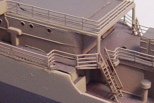 Railings aft on the 01 level near the boat davits
STEP 13 - COMPLETION OF THE FORWARD DECKHOUSE |
Im going to slightly violate my bottom-up assembly rule here. The problem is that the 2nd level shields for the bridge wings need to be added now. But, they also need to position correctly with and attach to the pilot house bulkheads. OPTIONAL - But even before that, Im going to glue a few GMM sailors to the 2nd level deck such that after the pilot house is added, they will appear to be inside of it manning the bridge. If you plan on adding sailors, on this particular day for which I am modeling (2 September 1945), enlisted men wore undress whites (no neckerchiefs) and officers wore standard khakis. Now, Ill add the pilot house to the 2nd level AND, more or less simultaneously, the wing bridge shields. This is a challenging four parts simultaneously added so that they fit correctly operation. But first, what parts are the bridge wing shields? They are shown in step 1 part G of the 1945 instructions. The trouble is that those instructions dont give you their part numbers. So you might refer to the 1942 instructions and discover that they are parts A33 (starboard) and A34 (port). This is correct for 1942. But, for the 1945 version, you will be very wrong! By 1945, on both Buchanan and Lansdowne, 20mm guns had been added near the rear of the bridge wings and the shape of the shields had been changed. The correct parts, which are referred to nowhere in the instructions that I can find, are parts P7 (starboard) and P6 (port). There is little latitude for the placement of the shields, which more or less must fit where they fit and thats all. However, there is at least some ability to fine tune the placement of the pilot house assembly. So, Ill attach the shields first and then very quickly add the pilot house, with some very slight adjustment of shield locations before the glue has set. Now (in accordance with the 1945 instructions step 1-G) lets add some of the detail to the bridge wings.
Thats all that Im going to add to the bridge wings at this time. The 20mm guns and signal lights (parts K22) are just too fragile and are traps for the rigging. There is a need for a bit of railing BETWEEN the flag bags. But the basic concept of the kit design fails here. That concept according to the 1942 instructions step 10 inset is that somehow the mast appears on the starboard side of this gap and the ladder to the deck appears to port. And that those items fill the gap and thus no railing is required. But, I assume, like the flag bags by my very careful measurement, that the mast is centered in the ship (where else would it be). Therefore, the kits instructions (or possible its design) makes no sense and just does not work. If you follow those instructions, the mast will be angled slightly to starboard not a good plan at all. Ill deal with the mast location and that bit of railing on an as required basis later on. On the other hand, if you are building a 1942 version, you still have a few items to add as indicated in step 1-G of the 1942 instructions.
Now its finally time to add the upper forward deckhouse assembly to the ship. Im going to delay the rest of the detail on the pilot house top because I need a flat area without detail that can be pushed on in order to get the assembly to snap into place. There really isnt that much to do. And it all can be done after the deckhouse has been added. So:
OPTIONAL PROBLEM There is one outstanding issue. It seems to me that there was almost certainly a 20mm ready ammo locker mounted on the forward 20mm gun tub. I have not been able to prove this, but in one of the photos that shows the open door on the shield, there is quite clearly something boxy looking visible through the door. And the kit does provide two extra single 20mm ammo boxes (parts A39) which only apply to the 1942 version. But, I just dont see any possible way that one of those would fit inside the forward 20mm tub and still allow room for a gun. In fact, the tub looks too small for a gun all by itself. Ill be looking into this more thoroughly when we add the guns.
STEP 14 - THE TORPEDO TUBES |
These are easy because the torpedo tubes provided in the kit are actually very nice with considerable detail. There are a few enhancements that could be made (file removal and replacement of some molded-in pipes here and there and just a tiny bit of extra detail around the firing station), but they are really very minor and Ill skip them. First, be sure you are using the quintuple tubes. There are variations provided with the kit. Add part D13 and paint it all Haze Gray tops bottoms and sides. Thats a bit unusual. Normally, in keeping with the camouflage plan, the tops would be Deck Blue. But, for whatever reason, for Lansdowne on the modeled for date, the tops were clearly Haze Gray. The visible ends of the torpedoes (visible on the underside) should be painted a Dark Gray. Despite being in a pseudo peacetime status, on this particular day, Lansdowne carried a full set of loaded torpedoes. Add the assembly to the amidships deckhouse.
STEP 15 - THE STACKS |
The first step is to correct the instructions; which seem to be identically incorrect in step 6 of both the 1942 and 1945 versions. The only serious error is that parts A52 and A53 are reversed. The inset instructions for assembly I (the top inset) is for the aft stack. The lower assembly J is for the forward stack. I recommend that you label them as such. If you get lost later on, the forward stack is a bit taller. Note that part A52 belongs with the aft stack and part A53 with the forward stack. Parts B4 and B6 are correct. B6 goes with the aft stack and B4 with the forward one. Both parts should be painted Deck Blue. You have a number of options concerning the stack bodies. In all cases, the sprue connections are in the worst possible places and a fair amount of filing will be required. You can choose to use parts that already have molded-in ladders and pipes - parts B5 (aft stack) and B3 (forward stack). If you make this choice, then you will also want to use parts B17 (aft stack) and B18 (forward stack) instead of the aforementioned parts A52 and A53. If you chose these parts, then you will add no PE ladder later. You can choose to use parts that do not have molded-in ladders (but still have molded pipes) parts A51 (aft stack) and A50 (forward stack). If you make this choice, then you will want to use parts A52 (aft stack) and A53 (forward stack). In this case you will need to add PE ladders to both stacks. You could also choose the A50/A53 combination for the forward stack and file off the molded-in pipes and replace them with bits of wire. This option does not apply to the aft stack, since it contains no molded-in pipes. In all cases, the stack caps are parts B9; which are identical and are not specific to either stack. Although, there is a good deal of PE work that can be done here. The instructions are correct that the aft stack pipes parts A29 and A43 belong to the aft stack and B21 and A44 belong with the forward stack. But, note that it is possible to add the assembled stacks to their bases (B6 and B4) such that they are rotated 180 degrees from their correct orientations. The stacks rake slightly aft. And, for the aft stack, the hole in the base for mounting part A29 is aft and port on the base (B6). For the forward stack, the hole for part B21 should be aft and starboard on its base (B4). There is a lot of room for improvement here in the instructions. My choice, among the above options, was to use parts A51 and A52 for the aft stack and parts A50 and A53 for the forward stack. I left the molded-in pipes on the forward stack in place. I will be adding PE ladders to both stacks and a lot of other PE items as well. After gluing together your choice of stack bodies and bottoms, you can go ahead and attach the stack caps (parts B9). Be sure to make use of the small locating pin forward and there is no possibility of adding them backwards. Also you may note that the caps are molded open. There is no need to drill and file in order to open these caps, as is the case on many other models. There is also no need to add PE stack cap grills, which dont exist in the GMM PE set anyway. These parts are very well designed. In order to assure correct positioning, Im going to delay the addition of the two pipes and caps (parts B21, A29, A44 and A43) until after the stack bodies, which are going to be painted Haze Gray, are attached to their bases (B4 and B6) which are going to be painted Deck Blue. Now there is a quite a bit of PE to add to the stacks. Well start with the aft stack since its just a bit easier. Aft Stack Assembly Now add the ladder right up the forward center. You can use part MA1. I chose to use some wide ladder from a generic GMM PE set; which is thinner, easier to bend and much easier to remove from its sprue. Well need two antenna connections one on each side (identified on the GMM PE sheet as antenna brackets). Follow the bending directions on the GMM instructions. Add them exactly amid each side of the stack. Their vertical location is different for each stack in such a way that it creates a line between them which is parallel to the deck. That works out if the brackets on the forward stack are located just below the lower footrail and on the aft stack located just below the upper footrail. Forward Stack Assembly The upper funnel footrail fits just as before, but rotated 45 degrees to port to allow an opening for the ladder. The lower funnel footrails dont work as well. GMM actually needs to design different lower footrails for the forward stack. The trouble is that if you rotate them 45 degrees to port, as is required for ladder clearance, then the opening for the aft pipe (part B21) will be rotated 45 degrees to starboard which was not the case. Those pipes (B21 forward and A29 aft) went right straight up the center of the stack. I solved the problem by cutting two segments of footrail off the port side lower rail, adding those two segments to the starboard side rail. That results in being able to position both with their ladder opening 45 degrees to port but their aft pipe opening dead center. Next Ill add Dragon PE part MA8 (whistle maintenance platform) as shown in the forward stack inset in step 6 of the instructions. Its actually shown somewhat more clearly in the GMM instructions. Then Ill add the GMM PE funnel platform railing as shown in the GMM instructions. OPTIONAL - The whistle platform you just added is actually the maintenance platform for the horn, whistle and siren; which are mounted on another small platform just above this one. Considering the extent of detail in this kit, Im quite surprised that this horn detail was not included. But, its easy to make from a little bit of styrene sheet, rod and wire. Add the ladder (part MA18) or in my case, some wide GMM generic ladder, offset 45 degrees to port. Now add two antenna brackets, one amid on each side, as explained previously, just below the upper footrail. There are two remaining GMM antenna brackets. In earlier years Gleaves class DDs had one aft on the MK37 support base and one center forward on the forward stack. But in 1945 Lansdowne, at least, had neither. I see no evidence at all that Lansdowne carried ECM antennas in 1945.
Now its time to paint the stacks Haze Gray and the insides of the stack caps Flat Black. The bases, as mentioned, should be Deck Blue. Referring to step 6 insets I and J of the 1945 instructions, add the stack assemblies to their bases (parts B6 aft and B4 forward). Be sure that after assembly, the extra hole for the stack pipes is aft and port on the aft stack and aft and starboard on the forward stack. Next well do one of the more challenging items in this kit - add the aft stack pipes (parts A29 aft and B21 forward). Remove them from the sprues with great care. They break easily. Ive done it. If your kit is like both that Ive built, you will also need to correct a slight bend in the middle of each pipe. Glue the pipes into their holes on the bases and lay them flat against the aft dead center of the stacks. Now add the pipe tops (parts A43 aft and A44 forward). Although I must admit that I really dont see a difference between them. Perhaps I would if I used a microscope. These could very well be the smallest plastic parts Ive ever seen. Be very careful. And to make matters worse, the sprue connection is on the top and most visible place on them. Do the best you can to clean that up. And, to make matters even worse, their shape defies holding with tweezers. Hint: its possible to grab them with tweezers with one point inside the vent hole. They should be added to the top of each pipe, pointing up and aft. These pipes and pipe caps should be painted Haze Gray and the holes inside the caps should be dabbed with a bit of Flat Black. OPTIONAL - Before I actually add the stacks, there are two minor items that I have seen in a photograph of the modeled for date, that I will add now while I can get to them.
STEP 16 - PILOT HOUSE TOP DETAIL |
Lets add the rest of the detail to the top of the pilot house. If you are building a 1942 version be sure to use the considerably different 1942 instructions. But for this one, refer to Step 1 inset D in the 1945 instructions:
STEP 17 - THE AMIDSHIPS SEARCHLIGHT |
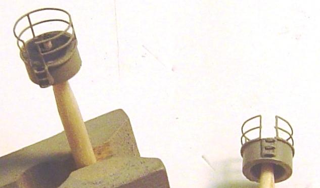
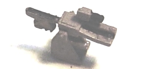
There were at least two different configurations for this assembly. Buchanan was as is represented in the kit. That is, a support tower and a basket shaped canvas covered railing around the searchlight. For that configuration you will want to follow the GMM instructions to replace the plastic tower from part K11 with the GMM PE tower. Above that use part K10 as the basket. Or cut off its canvas covered rails and scratch build some angular circular railings. Last, add a ladder to the basket forward. But Lansdowne does seem to have had the more common searchlight platform design. And with great luck and foresight on the part of Dragon (but they should have mentioned it) there is an otherwise unused part K9 that is a very nice representation of Lansdownes searchlight platform. The best photos of this platform can be found in photos of sister ship McCalla. It was about half the height of Buchanans. Its aft end was flat. It had one small central support tower and four support posts in its corners. Railing was 2 bar either canvas covered or not. On the day in question, the canvas was not deployed on Lansdowne. Access was via a short vertical ladder forward and port of the 20mm ammo boxes. The only trouble is part K9 doesnt fit! Well no surprise. Thats undoubtedly why they never mentioned it. Youll need to file off its mounting pin which is well forward of the mounting hole for Buchanan and you may want to fill that mounting hole. Youll also need to remove (thats right rip off) the double 20mm ammo locker just forward of the searchlight platform. It will move forward a bit and be mounted with side by side boxes rather than a fore and aft arrangement. Paint the bottom and support structure of part K9 Haze Gray. Paint its platform Deck Blue. Add 2 bar (3 counting the bottom) railings around the platform leaving a gap for a ladder just port of forward. Build and add the searchlight according to the inset in step 3 of the 1942 instructions. This is a bit easier said than done. Parts K40 and K39 are simple enough except of course for the incessantly poorly located sprue attachments. The clear plastic lens (part J1) is a nice feature if it fit right. But alas it does not, and requires some filing in places that are impossible to see, since its clear, which only tends to cloud the part. On my last build of this kit I painted the backside of the lens metallic chrome. That didnt help at all. This time I tried to put a bit of aluminum foil behind the lens. No luck, it just interfered with the parts fit. But, in the long run, unless the light was actually in use, its likely that the dark gray shutters were closed and the whole idea of a clear plastic lens is meaningless anyway. Now add the assembled platform with its flat edge aft, leaving just enough clearance behind for someone to squeeze by. Then re-install the double 20mm ammo box (part A45) just forward of the platform with the boxes arranged side to side. Last, add a short vertical ladder to the platform just port of the ammo boxes.
STEP 18 - THE FORWARD MAST |
Now Ill build and add the mast next. Yes it will be fragile. But, I want to add the rigging before the ship gets too crowded and complicated. So, fragile or not, the mast will come next. Also, since it is one of the most visible parts of the model, Ill devote considerable energy to it. The first thing you will notice is that the kit provides 2 parts for the mast. They must be kidding. There is just no way that it will remain straight and decent looking after the rigging and everything else is added. But even besides that, plastic masts rarely look good. They almost always bend just a bit and cause trouble. So, Im going to replace the plastic mast with one built from brass and aluminum. This is OPTIONAL. But its also pretty easy and will produce a much better result. I highly recommend that you give it a try. I also recommend that you assemble the two parts (B20 and B7) of the plastic mast and use that as a reference for positioning the various gadgets on the mast (as applicable for your chosen ship). The main length of the mast will be 1/32 brass rod cut to a length of 2 7/32. The lower portion will be 1/16 aluminum tubing cut to a length of 1. Insert the brass rod through the tubing so that just a touch extends out the bottom to act as a placement pin when we go to install the mast. Now we have quite a few things to add to the mast:
CAUTION The entire forward mast assembly is now incredibly fragile. Handle it with great care. Spray paint the whole assembly Haze Gray, being sure not to fill the halyard holes on the yardarm or interrupt the detail on the radar. The only other things to be painted are the ends of the four fighting lights. Of the three lights on each unit, the lowest light was white, the middle green and the top was red. The bell could also be painted brass, if you wish. Although during the war most brass was painted gray so as not to reflect sunlight. Add the mast to the ship gluing its bottom into the mounting hole and attaching it to the deck between the flag bags.
STEP 19 - THE MAIN MAST |
I know its nonsense, but the forward mast is always called that even though it sometimes looks like the "main" one. The next mast aft of that is the main mast. Its left over from sailing ship days. This refers to step 7 of either the 1942 or 1945 instructions. It looks really simple. Glue K34, MA23 and MA9 together and youre done. And, if you do that you will end up with a perfectly acceptable mainmast. Although once you start adding the antenna wires that attach to it do not be surprised if it bends (being plastic). And for Lansdowne at least, it will be incorrectly positioned! OPTIONAL Ill replace part K34 (the mast body) with a brass rod and part MA23 with some thin stiff wire. Part MA9 looks like it might work well enough, but it will need a small wire loop on its end through which the ensign halyard can be passed and it will be 2d rather than 3d, and being PE, it will not be very strong so Ill replace it. And speaking of that, well need a cleat on the aft edge of the mast to which the ensign halyard can attach. Additionally, I question the placement of this mast. Its pretty clear from several photos that, unlike Buchanan the mast rose from the aft deckhouse just aft of the MK51 platforms, rather than forward of them, and had an angular support post running forward between the MK51 platforms. OPTIONAL - So, the first step is to cut a piece of 1/32 brass rod to a length of 15/32 with the lower 1/32 angling about 10 degrees from the rest. The entire mast was swept about 10 degrees aft. Then add a very small collar cut from 1/16 aluminum tubing. This is to prevent the mast from falling endlessly into its mounting hole. Slide the collar about 1/32 above the bottom of the mast. OR - use the plastic mast and skip this step. OPTIONAL - Next, cut a bit of small stiff wire (I refer to this from time to time and am talking about the smallest model RC aircraft control wire that you can find) to the length of part MA23 and glue it to the aft top of the mast. OR - attach part MA23 to the aft top of the mast. OPTIONAL If you are not using the plastic mast, remove the plastic gadget from it that sort of looks like a surveillance camera and glue it to the aft edge of the brass mast at the same vertical location. I have no idea what this was. OPTIONAL Cut two pieces of small stiff wire to the length of the two segments of part MA9 (the ensign gaff) and attach them to the aft edge of the mast at the locations indicated on the plastic mast. OR - glue part MA9 to the mast. Then, in either case, we need something on the end of the gaff through which the ensign halyard can pass. Im somewhat intrigued by the GMM eyebolts. But one attempt at that failed. Ill certainly try them again later, but for now Ill use my normal technique which is to bend a very small piece of railing PE into a semi-circle and glue it to each side of the end of the gaff. OPTIONAL - What about a ladder? Its obvious that there must have been one since there were things up there that could possibly need repair once in a while. Its very difficult to see in photos of the time but there is without question some fuzzy thing that appears in portside photos of this mast, while, it does not appear in starboard photos. Ill add a narrow GMM ladder to the port side. OPTIONAL Like all masts, there were numerous electrical and electronic gadgets up there. And they need wires before they could work. That means, obviously that there were various cables running up the mast. So, Ill add a small bit of 32 gauge wire on the starboard side of the mast to represent a cable trunk. I have no information to indicate that it was on the starboard side. This is guess-work. But the portside was already used by the ladder. And, the aft side and foreword sides were blocked by several gadgets. So, Ill add it to the starboard side. OPTIONAL Okay, now last, we need something to which the bottom of the ensign halyard can attach. The geometry of this does not work very well. Photos show the halyard outboard and starboard of the surveillance camera gadget and passing it about midway in its length. The only way this is possible is if the lower end of the ensign halyard was attached to the starboard side of the lower mast or somewhere starboard of that. I chose the former and added a cleat (a short bit of railing appropriately bent) to the starboard side of the lower mast. Scratch built cleats at this scale tend to be a bit large but yet quite functional.
Now spray paint the assembly Haze Gray. As I mentioned earlier, the 1945 Lansdowne mainmast was not positioned forward on the aft deckhouse (as the kit would have us do). Instead, it was located just about even with the aft edges of the MK51 platforms. For Buchanan it does appear that it was located forward. Nevertheless, I am building Lansdowne so Ill have to do some work. First, there was an angular support brace traveling from very near the forward edge of the aft deckhouse up to the mast, just about even with the surveillance camera gadget. There was also an antenna trunk (a place for an antenna lead-in wire to attach) located at the far forward center of the aft deckhouse top (in other words, just in front of the angular support). Buchanan also had an antenna trunk at that location. Well be referring to this item later so lets give it a name aft antenna trunk. McCalla had a very different configuration with the catwalk between the amidships and aft deckhouse on the starboard side and the antenna trunk positioned far starboard on the aft deckhouse. Honestly, there just arent any photos of Lansdowne that I can find that make it 100% clear where the antenna trunk was located. So, Ill follow Buchanans example and position it as stated dead-center forward on the aft deckhouse. OPTIONAL But if you chose not to make the antenna trunk, then I really dont have any good suggestions about where to terminate the antenna. Antenna trunks are easy to make (figuring out where they were located is the hard part). Its simple just a short piece of .035 styrene rod cut to the appropriate length, in this case about 1/8 (enough to just clear the railings) and painted Haze Gray in this case. On top of that post glue a 3/64 bit of .025 styrene rod painted Gloss Black. That is the insulator and is the place where the antenna lead-in wire will eventually attach. Glue the trunk against the forward railings on the aft deckhouse, just in front of the old mast mounting hole. Now, if you are building Lansdowne, or I dont know what other ship, you will need to remove the forward mounting hole. I added just a touch of putty. Its a minor point since the angular mast support brace will most likely conceal it anyway. And, again for Lansdowne, drill a 1/32 new mast mounting hole dead-center even with the aft edges of the MK51 platforms. Add the aft antenna trunk in the center of the deckhouse as far forward as possible. Add the ensign and its halyard now while its easy to get to and add the mast to the ship. CORRECTION - If you are building a 1945 Tokyo Bay version of any ship, on that day all ships in the bay were ordered to fly an ensign from the highest point on the ship (in this case the foremast). I did not discover this until much later in this build (step 33). So, if that is your model, do not add an ensign to this mainmast gaff only a halyard. Last, add the angular support brace. The sticky back flags in this kit are interesting and are much easier to use than the old standard decal on aluminum foil technique. But the darn things wont bend. They just snap right back to their original shape flat! I may go back to the foil method next time. Flat is just not realistic. 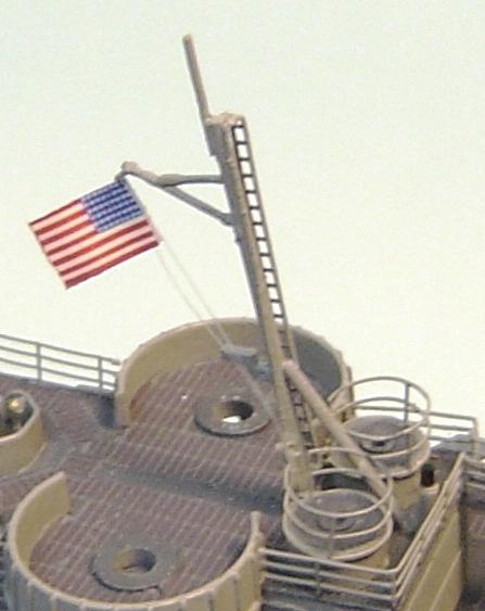 Mainmast, ensign halyard & antenna trunk added
STEP 20 - THE RIGGING |
Rigging is, of course somewhat optional. If you are doing an Out Of the Box build, then you may not wish to add it. But if you are working OOB, I doubt that youve gotten this far in this document anyway. Rigging comes in five types:
The design layout discussed below is the best I can come up with. Its always difficult to even see the rigging in 1940s photos. Plans are always good. But they are only plans and ships often turn out different due to last minute changes by either the yard or the crew. Designs (particularly in antennas) also changed from year to year and ship to ship. This design is based on photos of this and sister ships in various years (generally stays did not change unless there was some significant change in the mast). And last, its often based on very detailed close-up photos that may show a turnbuckle or eyebolt here or there with some thin line running upwards to who knows where. That where can often be figured out from other photos. I will be adding turnbuckles and perhaps eyebolts (from the GMM PE) as required. That is optional, but if you dont use them, in many cases you may have difficulty attaching the ends of various wires and rope. And simply gluing it to the deck is not something I would do. There are many good ideas about what material to use for rigging. Of course stretched sprue is the old traditional method. Paint brush bristles (from large brushes) are another idea. They are stiff, come in colors and can be cut to any exact length. Many modelers use thin fishing line. Some use very small gauge wire. Some use mylar line, but it usually doesnt glue very well. Others use silk thread. I happen to use human hair. Its strong, lasts for thousands of years, can be easily dyed to any color and instantly sticks to CA glue even faster than fingers. I will be using double lengths of rigging for halyards, so something that can pass through the eyebolts on the yardarm and then back down to where it started is required. That rather eliminates stretched sprue and brush bristles. For the antenna wires Ill also be adding insulator stand-offs to keep the wires from touching the ship. Ill explain that later. But for now just know that something very thin is required. Nevertheless, use whatever you are most comfortable with. Ill just be explaining where, and with what device, to make the end attachments. THE HALYARDS Weve already done one of the halyards on the ensign gaff on the mainmast. Later well add a couple more halyards on the bow and stern staffs. That leaves the signal flag halyards between the flag bags and the eyebolts underneath the yardarm. Its not easy. So take your time and be very patient. Also note that in this design all halyards must travel aft of the lower fighting lights and aft of the yardarm footropes. ADDITION - If you are building a 1945 Tokyo Bay version of any ship, on that day all ships in the bay were ordered to fly a large ensign from the highest point on the ship (in this case the foremast). I did not discover this until much later in this build (step 33). If that describes your model, add an eyebolt to the aft end of the radar maintenance platform and a halyard and ensign to that point from the starboard flag bag. See step 33 in this document for more information and photos.
THE FOREMAST STAYS One pair of stays (one stay per side) passed from the lower attachment point outboard to a turnbuckle outboard of the flag bags. Another pair on each side passed from the lower attachment point aft and outboard to turnbuckles outboard of the forward stack. Another pair of stays passed from the upper attachment point forward on each side to turnbuckles attached to the support structures that were added to the sides of the pilot house back in step 10 of this document. The single last stay passed from the upper attachment point aft to a turnbuckle in front of the aft stack. Be very careful! I usually damage about one item for every two that I add in this step. The turnbuckles are difficult to use. The holes should be just a tiny bit larger. Magnifying glasses may help.
THE ANTENNAS The layout for the antenna wires is not the easiest thing to be certain about. Again, fuzzy old photos, dubious drawings and plans that dont seem to match photos are the source of the trouble. Nevertheless, there are a few things that are fairly certain for Lansdowne. First there were several basic connection points: The routes taken were as follows: There were probably several antenna lead-ins, but they are invisible in photos. The only obvious one attached to the aft antenna trunk (from step 19) and connected to both of the wires attaching to P1 and P2 forward of the insulators. Actually point P9 most likely also served as a lead-in connection. Some plans, but very few photos, also show wires between points P5/6 and some unidentified location near the forward edge of the main deck. However detail photos of Lansdowne in 1945 show no connections in that area. Youll also need connector wire loops passing around P3, P4, P5 and P6. Work from the bottom and inside up and out and take your time. This configuration is difficult to explain. Check the photos online and the photos below. By the way, it appears that Buchanan was very similar in 1945 and only a bit different in 1942. Note that there are certainly other possible interpretations of the fuzzy photos many of which actually conflict with each other. Is that due to changes or just invisibility of wires in some photos?
STEP 21 - THE FANTAIL AND DEPTH CHARGE RACKS |
To PE or nor to PE, that is the question. Excellent quality depth charge roller racks can be made from the GMM rack PE and 1/16 rod (for the depth charges). But, no matter how much time you spend on the depth charges they wont look as good as molded ones. Meanwhile, not surprisingly, the plastic depth charge roller racks (complete with depth charges) that are provided with the kit have super detail. The only trouble is the obvious joint along the top where the two halves meet. That will need some filling and filing. Last time I built this I used the plastic parts and was quite pleased with the result. So, I think Ill do that again chose not to PE. But first, refer to step 5 of the 1942 instructions and build two smoke generators from parts K23, K24 and K25. The detail is astonishing. But, of course, they dont fit together very well. In order to get K25 to fit you will most likely need to file off the two part mounting pin on K23/24. Now comes the part thats rather odd for Lansdowne. Excellent photos of her fantail taken in 1943 and 1944 very clearly indicate only one smoke generator mounted on the port side. Photos in 1945 provide no additional information regarding smoke generators. What to do? Interestingly, of Lansdownes nearby sisters, all except McCalla appear to have carried two smoke generators. But, McCalla also only carried one to port. Hmmmm - so it was not some unique quirk associated with the photos. Bottom line Ill just add one smoke generator portside. Depending on your choice of ships you may want to add them both. Now build the depth charge roller racks. As mentioned, Ill use the plastic ones and Ill spend a little extra effort to get the parts joint between K32 and K33 looking good. OPTIONAL - It is possible to enhance the kits depth charge racks just a bit. There are no cross bars on the top of the plastic racks. Use the bottom piece from the GMM PE racks instead and place it on the top of the plastic racks. You can also add a release lever (made from a short bit of PE sprue) on the inside edge of the racks. Take a look at the GMM PE racks. Note that once these levers are added, the racks become port and starboard versions. Add the racks and one smoke generator portside. Note that there is something wrong with either the racks or those pads on the deck that the racks mount to. If you align the racks with the fronts of the pads, released depth charges would bounce off the deck which is not good. The racks should hang over the aft end of the ship and thus must be mounted a bit aft of the front of those pads. There does appear to have been a short bit of railing where the starboard smoke generator would usually be. Well also need an ensign staff back aft. That will probably be from the GMM PE set and therefore exceedingly fragile. Ill wait and install both the staff and the railing almost last in this project. Most photos also show a davit between the aft deck hatch and the roller racks. And, of course the aft deck hatch still needs work as well. Those items will be dealt with in the next step after the after main deck railings have been added. 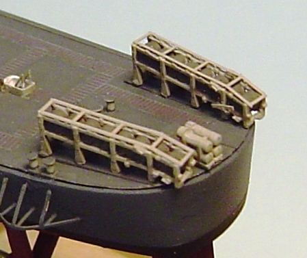 Depth charge racks and smoke generator completed
STEP 22 - CORRECTION OF AMIDSHIPS TO AFT DECKHOUSE CATWALK AND LIFE RAFT RACK |
You try hard to find all possible photos before you ever start a build. But, that doesnt always work out. While searching for additional information I have stumbled across a photo of Lansdowne in 1942 that very clearly demonstrates that the catwalk between the amidships and aft deckhouses was on the starboard side. If you are building Buchanan, the kit is correct the catwalk should be on the port side and you can ignore this step. But for Lansdowne (and McCalla at least) it was starboard. Otherwise things were pretty much the same but reversed. So, Ill need to now remove a few rails around the catwalk area, cut the catwalk out of its port location, relocate it starboard and replace the rails. If you are following this process and got here due to the reference in step 5 of this document, then relocate the catwalk now and reverse the rails in the area. Unfortunately all photos in this document prior to this point will show the catwalk on the incorrect side for Lansdowne. Ill also add a vertical ladder on the front of the aft deckhouse just starboard of center that is clearly shown in the mentioned photo. Now we should also correct the more forward aft life raft rack. Since my original design of this rack it has become apparent through photos that the top of this rack was nearly parallel to the main deck instead of angling downward and outboard. So, Im going to remove and replace that rack. The top portion of a Fletcher class life rack raft is still usable. Or if you wish, a short bit of styrene or brass sheet cut to fit will work fine. But instead of using the entire Fletcher class PE rack, Ill replace the vertical part with the longer extra part MA19s from the kit. 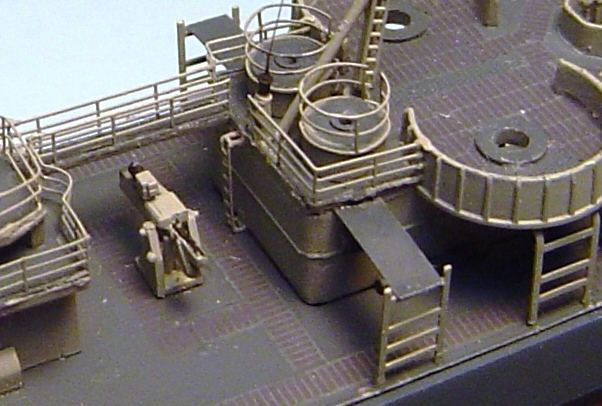 Catwalk moved to starboard side, vertical ladder added and life raft racks changed
STEP 23 - K-GUNS, RACKS, DAVITS, AFT RAILINGS AND OTHER AFT DECK DETAIL |
This is pretty much a catch-all step that will attempt to nearly complete the aft main deck detail. The first step is the K-guns and associated racks and davits. As explained much earlier, this deck was molded for the 1942 version with its several individually mounted depth charges. In 1945 both Buchanan and Lansdowne carried two K-guns per side (rather than the 1942 configuration of 3 per side). Next to each K-gun was a single row (mid-war design) depth charge rack. Thus, long ago, we filled all mounting holes on the deck and have a smooth surface to work with now. The first decision, once again is to PE or not. And, once again I know that the GMM PE, in combination with scratch made depth charges, will make a very nice looking set of K-gun racks and launchers. But, I am also very curious about using the plastic parts and just taking a look to see how they turn out. So lets do that first. If you are building a 1942 version, just ignore this and follow the 1942 instructions. Its not difficult at all. Therere just a lot of small parts. But, for a 1945 version refer to the inset diagram in step 5 of the 1945 instructions. Combine parts P1 and P8 four times. CAUTION part P8 is very fragile. I broke 3 out of 4 just removing them from the sprue! Interestingly, there seem to be no mounting pins that need to be removed. Apparently Dragon assumed that we would eventually figure out that the deck was not designed for these parts. Now bend and add parts MA32 (starboard) and MA30 (port). Be sure that you bend and assemble correctly or you may not end up with two for each side. If you have chosen to use the GMM photoetch for the K-guns, follow the GMM instructions and again be sure you bend correctly and end up with two for each side. Youll have to make the depth charges from plastic rod. Earlier I delayed addition of the K-guns in order to coordinate their locations with the railings. I thought perhaps that the K-guns were mounted all the way at the deck edge and there was no railing outboard of them, as is the case with many other destroyers. But that seems not to have been the case with either Lansdowne or Buchanan. So, go ahead and add the K-gun racks that we just made to the deck, a bit inboard from its edge, such that there will be room for the railings outboard of the racks. There are no mounting holes, so use the various top down views in the instructions as a positioning guide. So far weve just been working on (and adding) the K-gun depth charge stowage racks. The actual K-gun launching devices are parts K6. You will need four of them. You will also need to clean up the sprue attachment which is right in the very most visible spot on these otherwise difficult to see parts. And, since all mounting holes have been filled, trim off the mounting pin. OPTIONAL - There is room for some improvement on part K6. A small chain wrapped around the depth charge when it was on the launcher and held it in place. Ill use a small bit of hair for that. Also, the firing mechanism had a small adjustment hand wheel on top of it, if you would really like to be accurate. Add parts K6 such that the depth charges seem to rest on top of the aft extension of parts MA30/32. In theory, if everything fit perfectly, that would coincided with the base of K6 sitting on the deck. But, such is not the case. The French judge awards a 3.2 for being close. You will need to settle for the K6s sitting on the MA30/32 extensions, but not on the deck. Now I understand why the racks didnt sit quite level after MA30/32 were added. Like most other Dragon PE, MA30/32 are just about 10% too large. There are only a few things remaining to do aft. The aft main deck rails are next. Well use the GMM PE and be sure to pay attention to the port (left) and starboard (right) variations. Now Ill add the davits by the K-guns. Its a tough choice here. The GMM ones have some very nice detail, but they are flat. The plastic ones are round (and therefore will glue more firmly) but have no detail. Ive added turnbuckles to them before and made them look pretty good. I think Ill use the GMM ones. Locate them just aft of the launchers. OPTIONAL - In nearly every photo I see of Lansdowne there is another davit mounted about half way between the aft deck hatch and the forward end of the depth charge racks. In photos it appears somewhat heavier duty than the K-gun davits. Ill use one of the plastic davits from the kit and add a turnbuckle to it. OPTIONAL - Now lets complete the open hatch aft. Ill use a GMM generic hatch with a scuttle added to each side. Paint the underside white and the top Deck Blue. Glue it to the forward edge of the coaming and add two supports made from a bit of PE sprue. OPTIONAL - And last, a good photo of Lansdowne shows a medium size cable reel mounted near the rails outboard of gun 54 on the port side. Several lower quality photos of both sides show some dark lump in that same location on both sides. So, Ill add two cable reels in that location. Ill make them from GMM generic cable reels PE but the kit provides extra plastic ones if you prefer. As mentioned before, Ill leave the ensign staff, its chock and a bit of railing aft for very nearly last.
STEP 24 - CHOCKS, WHALE BOATS AND DAVITS |
In this step well complete the whale boats and some other detail amidships. But first, the chocks need to be added amidships so we might as well add them everywhere. The kit provides open chocks (part K4), closed chocks (part K12), one oversized closed chock (part K14) for the stern and a closed chock (part K35) integrated with the jackstaff for the bow. The instructions provide very little information about where these are all placed. But, since the railings have been added, its easy to figure out now. I have specifically waited to add the chocks until after the railings have been added. Otherwise there would be very little chance for the two items to coordinate. As for types:
I cant say with certainty that that layout is correct for Lansdowne in 1945. But there are no spares of any types, so there really isnt much choice. Be careful! They are very small, easy to lose and (once again) there are no spares. Also you probably will never be able to get these to actually look good. Just okay is probably good enough. The actual boats are next. Lets first talk colors. Unlike many other whaleboats that had their below water-line hulls painted black, an excellent photo of Lansdowne taken on the momentous day clearly shows that the whale boat hulls were the same color as their upper portions Haze Gray. Also on that particular day, other photos clearly show that she did have the canvas (nearly white looking) covers deployed over the whaleboat bows. Ill use a light tan color that I mixed up some years ago to represent fairly clean canvas. There is no doubt that the ship was very clean on this particular day. The inside of the boats is your choice. There was wood, and any tan or brown colors would be appropriate. The few B&W photos of whaleboat interiors from those days are not that much help. Usually there was more random canvas lying about than anything else. This is your chance to be artistic and create a whaleboat interior that would have made Adm. Halsey proud. Refer to the inset in step 9 of either the 1942 or 1945 instructions and combine parts K15, K20 and K47. However, the 1945 instructions fail to mention part MA4 (the rudder) which should be added to both boats. Or you could use the GMM PE rudders (which have a slightly nicer tiller, but no connection to the hull at the bottom). Additionally those little stubs of propeller shaft just scream for the GMM PE brass propellers. 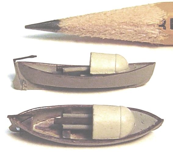 Whale boats assembled, painted and ready to install Next we need to add the whaleboats to the ship. Easier said than done. If this isnt planned well it requires a simultaneously holding four parts in place (defying gravity) while the glue sets. And if you intend to include boat davit pulleys, that would be six parts. Lets review what those parts are.
A few issues should become obvious during very preliminary test fittings.
All of that assumes that the boats will be shown in their stowed position fully inboard, which does seem to have been the case in the 1945 photos of Lansdowne. Evidently, Lansdownes boats were never actually used on that day. If you would prefer to show the boats swung out, you are on your own but things should fit much better as there is no ultimate bottom to interfere with the boat height. I actually drew up a 1/64 scale plan for the boats and everything seems to fit with just enough space if the above changes are made and if the forward davit points straight aft and the aft davit points inboard and slightly aft. That means that in order for the boat to sit level, the aft davit needs to attach to the rudder tiller. This was almost certainly not the case. But what do you know photos of that day pretty clearly show that the boat was not level! Its stern was clearly higher than its bow. So, the aft davit can attach to the platform below the tiller or maybe just inside the stern. And it all works. Brilliant! I give huge credit to both Dragon and GMM for designing parts that are just the right size to make all of this fit together perfectly. Well, well see about that as we build it. First, trim off the point below the small round blob at the top of the davits and glue a GMM pulley to each round blob. Position it outboard so it looks better and now you have made starboard and port versions of each davit. Make sure the pulleys are glued on firmly. They will need to fully support the boat and they will get messed with a bit before the boats are in position. Now glue the forward davit pointing straight aft and, after a test fit of the aft davit and the boat, glue the aft davit pointing inboard and about 10 to 15 degrees aft. Let those items dry and then glue the boat, carefully holding it in place for a few moments, to the bottom of the davit pulleys. Add the manropes, cut to the correct length, between the tops of each davit. OPTIONAL - The only thing left is the various lines that were associated with the boats. Each davit had a line from its top pulley to some attachment point. The forward davit line attached to a point on the lower davit. The aft davit line attached to a turnbuckle mounted on the inside of the amidships spray shield just aft of the most forward amidships bit. Close study of photos has shown that the marker floats on the bridge wings that were painted red back in step 13 should actually be Dark Gray. If you missed this correction in step 13, do it now. OPTIONAL - The locations of the boat booms on Lansdowne in 1945 remain a mystery. In 1943 photos they are obviously deployed alongside the main deck just forward of the boats. Some sister ships show them stowed just outboard of the forward stacks. In fact on Lansdowne in 1943, that also seems to be a stowage location. On other destroyers they were stowed inside the amidships spray shields (bulwarks). Unfortunately in 1945 there are excellent photos of all three locations on Lansdowne and there are no boat booms to be seen. Ill close this bit of research now and conclude only that they were evidently difficult to spot wherever they were stowed and are therefore not very significant in this model and will not be added. You might think, as I did, that this is a good time to add the torpedo crane (part D5). But, if added before the 20mm guns, it only makes it much harder to add the gun. The crane will be postponed for now. 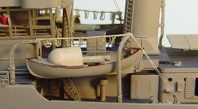 Whale boats completed - port view
STEP 25 - THE MK37 DIRECTOR, RADAR AND REMAINING DECKHOUSE DETAIL |
Photos establish that like Buchanan, in 1945 Lansdowne had a standard MK37 director with a MK12 radar mounted atop. Neither ship carried a MK22 radar. Refer to the inset in step 2 of the 1945 instructions. OPTIONAL first Ill file the molded ladders from part E13. Ill replace them later with PE ones. Then combine E13 and E10. Test fit that assembly into part B8 already mounted on the pilot house. It should be a very easy fit. There are three choices for the MK12 radar
Ill use the third method. Regardless of which radar you build, you also have a choice concerning which radar support stand to use.
So, Ill first build the MK12 radar (without a MK22 unit) using the Cyber-Hobby parts ME, MF and MD20. This is not quite as easy as it somehow should be. Youll have to properly align the four MD20 parts on part ME so that part MF slides through all four MD20 holes. Test fit MF after each MD20 is added. Then, surprise, part MF is not cut to the correct length and youll have to shorten it so that it just barely extends beyond the outside MD20s. Then Ill attach that to the top of the MK37 unit using Dragon parts E2 and E11. Once in a while the top of a MK37 was painted Deck Blue. I see no evidence of that for Lansdowne in 1945, so Ill go ahead and attach the radar assembly to the MK37 before painting the entire assembly Haze Gray. OPTIONAL you could add some very small GMM generic hatches to lay over the six hatches on the MK37. But the plastic detail is already pretty good and I really dont see an advantage in PE hatches. You could also drill open a few hatches; which was not at all unusual for that crowded space. Ive done that before and its quite difficult to get it looking good for very little improvement in the overall model. So, Ill skip both of these steps on this build.
After its all painted Haze Gray, youll need to paint the bloomers. Just as around many gun barrels there were canvas/rubber bloomers that surrounded the movable manual aiming sights on each side of the MK37. Paint those bloomers Flat Black. And, weve delayed the addition of the side ladders until after the bloomers were painted so add the ladders now. There was also some post like gadget mounted on the bracket on the aft edge of the MK37 base unit (that we added back in step 16). In earlier years the bracket may have been an attachment point for an antenna or mast stay. But in later years, photos show no evidence of an attached wire, but do show some gadget mounted there perhaps a light? Now add the MK37. If your model is cruising in a non-combat situation, the heading of the MK37 is fairly meaningless. But, if you are modeling a combat situation, the MK37 was the director for the 5 guns and wherever the MK37 pointed, the 5 guns also pointed. Last, add the postponed signal lights (K21 and K22) to the bridge wings as shown in step 1G of the 1945 instructions. Thats it. There is some value in mentioning the configuration of the 20mm guns in the aft bridge wing corners. For this class of destroyer there seem to have been at least three designs, and probably more, that varied through the years. One design (generally early war) had searchlights in the corners mounted on raised platforms. A second design (generally mid-war) had 20mm guns also mounted on raised platforms with a small height of railing (rather than shield) surrounding the guns. The third design (generally late war) had 20mm guns mounted at deck level (instead of on raised platforms) with shields surrounding the guns at a slightly lower height than the rest of the bridge wings. This 1945 kit is designed for the third option. The 1942 Buchanan kit is designed for the first option. Lansdowne appears to have experienced all three designs in her career. But in 1945, photos indicate she had the third design, as did Buchanan. For any other ship, consult your photos. 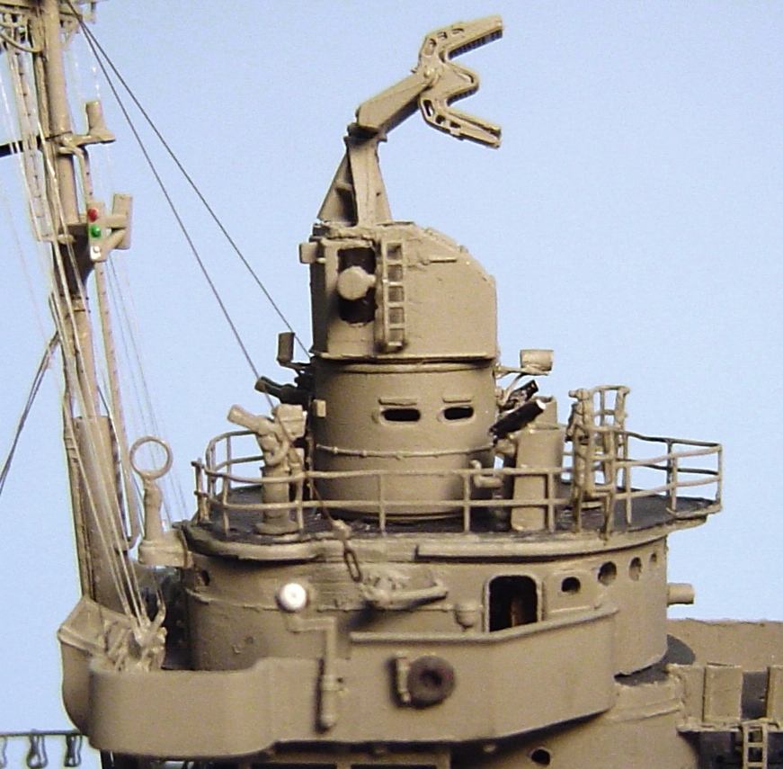 MK37 Completed
STEP 26 - SOME FORECASTLE DETAIL |
In step 28 well be adding the 5/38 guns. But before adding them, I want to complete some additional detail on the forecastle.
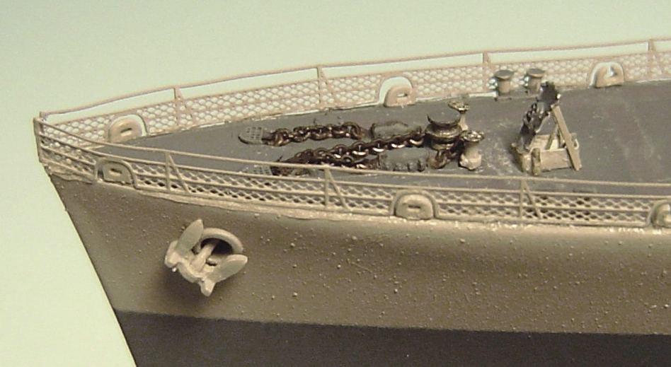 Completed forecastle detail
STEP 27 - CORRECTION OF LADDERS AFT OF FORWARD DECKHOUSE |
Once again, while searching photos it has become evident that the arrangement of the ladders is incorrect on the lower foremast and on the aft end of the forward deckhouse. This is a large and difficult change that I wish had been discovered before the boats were added. As it is now, the port boat may need to be removed (either intentionally or accidentally) in order to make the change. First, the problem should be explained. This 1945 Buchanan kit suggests one long ladder on the aft end of the forward deckhouse extending from the top of the amidships deckhouse (01 level) all the way to the bridge level (03 level). And, in all years this seems to have been correct for Buchanan. So if you are building that ship, you can ignore the rest youve already done it properly. But, that turns out to unfortunately not be the case for Lansdowne (I think). There is an excellent quality detail photo of Lansdowne in Tokyo Bay in 1945 that in its far corner shows just a part of an unexpected platform with rails on the 02 level just to port of the foremast. Its a very minor detail that could be ignored. But recent study of excellent photos of sister ship McCalla have explained that mysterious platform. McCalla had a different arrangement in this area than did Buchanan. She had a small platform adjacent to and port of the foremast on the 02 level and a vertical ladder from the amidships deckhouse top (01 level) to that platform. From that platform she had a ladder on the port quarter of the foremast extending up to the 03 level. The large ladder that spanned two levels was not present. The appearance of that 02 level platform in photos of McCalla looks identical to the mysterious platform on Lansdowne. So, it looks like I have some work to do. If you noticed the correction notes earlier in this document and are here by referral from those points, then read on, ignoring the removal instructions and paying attention to the addition instructions. You and I will need to accomplish the following:
STEP 28 - THE 5"/38 GUNS |
A brief word on quality normally the 5 guns are just about the poorest quality items on any plastic model. I almost always replace them with some third party units. But, these guns are actually excellent and accurate. So, well use them. Ill also mention that in this discussion Ill be talking about left and right as they apply to the gun with the barrel considered the front. This applies to the guns and has nothing to do with starboard and port. First lets get organized. Like all guns, 5/38 guns were numbered from bow to stern. The most forward was called gun 51. Next was gun 52, then 53 and last 54 (in the case of this 4 gun ship). There were also two types of 5 guns single knuckle and double knuckle. The double knuckles were the ones mounted in front of another gun in this case guns 51 and 54. They were slightly different in order to absorb the shock wave of the firing of the gun just behind them. Meanwhile, guns 52 and 53 were single knuckle guns. But, you cant see these knuckles since they were part of the gun mount structure. Nevertheless, you can tell them apart. Single knuckle guns had an extra hatch forward left and on top of the gun that was often opened as an air vent. Double knuckle guns did not have these hatches. If they did and the gun behind fired, everyone inside (yes there was a crew inside these things) would probably die. In this kit, single knuckle gun bodies for use in guns 52 and 53 are represented by part G2. Double knuckle guns are part G1. Now for the instructions. The 1945 version seems to only describe the assembly of the double knuckle guns assembly C. So forget that inset in the 1945 instructions step 2 and instead refer to the 1942 instructions step 2 insets B and C. Inset B shows the assembly of a single knuckle gun and inset C shows a double knuckle gun. In all cases the bases are part G3. Thats actually where the primary difference between the gun types was located. But it cant be seen, so it doesnt matter. These instructions also give you the option of barrels part G4 or G5. That depends on whether you want bloomers or not. Bloomers were canvas/rubber seals around the barrels that kept dust, smoke and water out of the gun interiors. Bloomers were normally installed at sea. And, in 1945 its very clear that the bloomers were installed on Lansdowne on the modeled for date. Check photos of your selected ship to determine which barrels you should use. OPTIONAL Double knuckle guns also had a rectangular shield over the gun captains hatch on the right rear top of the guns. This was so that the captain of a double knuckle gun wouldnt get his head blown off when the gun above and behind him fired. These shields were removable. However, Lansdowne clearly had them installed on guns 51 and 54 on the modeled date. So we need to build 4 guns: In all case well use part G3 for the base and either part G4 or G5 for the barrel depending on whether you need bloomers. If you chose to use the barrels with the bloomers, ignore the instructions that imply that you should add the barrels before the gun body. That just wont work. Combine the bases and the bodies and then add the bloomer barrels. This does require that the barrels be positioned in their shipped (at rest and not in use) state. If you wish to depict barrels with bloomers that are in action and pointed at various angles, then you will need to use the non-bloomer barrels and make your own bloomers from any number of sources (putty, white glue or aluminum foil are the usual methods). Start by assembling the selected barrel (G4 or G5), the base (part G3) and two parts G2 (guns 52 and 53) and two parts G1 (guns 51 and 54). Label them on their bottoms as gun 51, 52, 53 or 54. It may seem now that guns 51 and 54 are identical as are guns 52 and 53, but after we evaluate other items, that may not turn out to be true. So mark each gun 51 through 54. Also, if the barrels look off-center to you, that is correct. They were and should be. And, that is the normal trouble with most plastic single 5/38 guns. They are not off-center. At this point you have four very acceptable looking 5/38 guns. But there is still considerable room for improvement. Everything beyond this is OPTIONAL. OPTIONAL Ill add the gun captains shields over the hatches on guns 51 and 54. These varied somewhat in design and placement from ship to ship. But in all cases they can be easily made from some thin brass and styrene sheet. OPTIONAL The hatches on the sides near the rear of the guns were the access doors. You could open some of these if you wish. They were often open. But all of them had a short rung ladder below the doors and a hand hold (made from a short railing segment) just behind them. OPTIONAL All 5 guns had a vertical ladder to their tops. The locations of these varied significantly from gun to gun and time to time. You will need to carefully examine any photos that you have. In 1945 it appears that all four guns on Lansdowne had these ladders mounted on the left side of their back walls. More typically, the locations of these ladders vary between guns and therefore distinguish each gun individually. OPTIONAL There were gun sights (for manual operation) mounted just in front of the gun captains hatch. GMM makes some excellent detail 5 gun sights that are included in their battleship PE sets and you may have extras. If not, a GMM 20mm gun sight works well enough and if you have used almost any GMM product before, you probably have extras. Note that the actual sight targets should be Flat Black, so delay their installation until after the gun assemblies are painted. 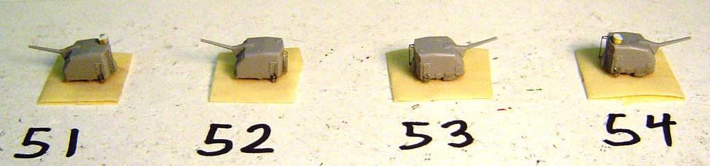 5"/38 guns ready to paint Now spray paint the guns Haze Gray and, if applicable, paint their tops Deck Blue. Paint the bloomers, if you used them, Flat Black or a canvas color depending on your ship and date. Last add the optional gun sights if you wish. Add the guns, posed as you wish.
STEP 29 - 40mm GUNS AND MK51s |
These dual 40mm Bofors guns epitomize everything that is good and bad about this kit. The good part is that they are probably the most detailed 1/350 scale 40mm guns Ive ever seen (plastic or not). But thats about it for the good. On the bad side, the parts dont fit, the sprue connections points are very poorly planned, the parts are just too small and fragile and, of course, the instructions are horrible. Anyway, here we go. Referring to the inset in step 3 (or is it 4, I cant tell) in the 1945 instructions start by removing parts Q1, Q3 and Q4 from the sprues. Take great care with parts Q3 and Q1 and clean off all sprue remnants. If you miss something, the parts just wont go together. Take great care because often the sprue remnants that you need to remove are nearly hidden behind detail that you will want. May I suggest that even before cutting the parts from the sprues you should paint or marker color the sprue connections so that later you will know what should be removed and what should not. Additionally, the mounting pins on the bottom of part Q4 do not even come close to fitting into the holes on the deck. That would be a big surprise if after you built these very fragile items, you were to discover that they didnt fit. Take the time now to file the mounting pins or enlarge the mounting holes. The instructions rather imply that part Q3 mounts to part Q4 wouldnt you say. No, thats wrong. The round base on Q1 mounts to part Q4. But, of course, it doesnt fit. So file the round base on Q1 until it fits into the top of Q4. Then part Q3 mounts to the front of Q1 and to the top of Q4 simultaneously. But, it doesnt fit. There is a small tab on the lower left of the back of part Q3 and a somewhat smaller hole on Q1 that it is evidently intend to fit into. You will have to file that tab to about half its original size. Also file flat both the lower front of Q1 and the back of Q3. There were sprue connections here and if the surfaces are not very flat, things wont fit. Be very careful that part Q3 mounts square in all dimensions or later the barrels will look crooked. Part MA27 is next. The instructions include a decent drawing about how to bend these but leave you pretty much clueless about where they should mount. They were the seats and foot pedals that the gun operators used. After installation the seats should be parallel to the deck (they are the seat bottoms only), the rails in front of the seats should angle downward and the foot pedals should bend back up. The arrangement is just like a car. There is a small ledge behind part Q3 just above the flat platform of part Q1. Thats where the center of MA27 should attach. Unfortunately, there is some part of something down there that prevents it from being perfectly level close but no cigar. So, do the best you can to get the seats level, pedals down and forward and after the glue dries, bend just a touch as required. Be sure that both seats are inside the edges of part Q1 or there will be trouble later. Now well add the operators handwheels (parts MA16). The instructions only show one handwheel being mounted on the right side of the gun. I assure you, there were two one on each side. One adjusted the bearing and the other the elevation. They were a bit tricky to aim but you got used to it. The PE does provide four. In this instance only the instructions are wrong hmmm no big surprise there. They should be bent as shown and mounted on the gun sides such that they would be directly in front of the operators seats at hand level. There is a small pin on the right side of the gun where the handwheel should be added. The instructions also show a pin on the left side, but its not really there. Add the left handwheel near the top of the small rectangular protuberance on the left side. And next well go to the GMM PE instructions and add the railing that surrounded the back of these guns. The instructions are obvious enough and an extra one is provided. 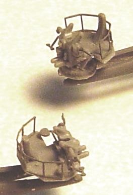 40mm Bofurs guns ready to paint Thats it for now. There are still a few parts to be added but they will involve some multi-color painting. So paint the entire above assemblies Haze Gray. Be very careful removing the barrels (part Q2) from the spue and again while cleaning up the attachment points. Paint the recoil areas on the barrels Flat Black and add them as shown in the instructions. Last, add the gun sights. You have a choice of using the kits part MA31 or the significantly higher detail GMM sights. The choice is obvious. Paint the sight targets Flat Black. Add the sights on top of the barrels just behind the recoil area. OPTIONAL - Before I add the gun assemblies Im going to add an ammo rack inside each gun tub. Several years ago I bought a large quantity of GMM PE 40mm ammo racks. They mounted inside 40mm gun tubs and served as storage locations for the 40mm ammo cartridges. But, they never fit inside anything except the tubs for which they were actually designed. In fact, in most cases 40mm gun assemblies by themselves just barely fit inside their tubs. Theres a lot of poor parts scaling going on out there. But, what do you know; there is room inside these tubs for the racks. So, Ill trim and bend them (they were designed for quad 40mm tubs rather than dual tubs) and add them. There were usually four layers but in this case one is enough. Four dont fit anyway. 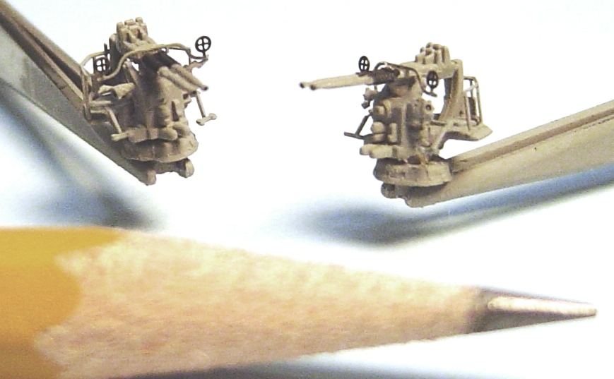 40mm Bofurs guns ready to install Now add these excellent detail guns to the ship. In a non-combat situation these guns were normally trained aft. Last, build (as described in step 15, part 4 of this document) and add two more MK51 directors to the tubs just forward of the 40mm guns. To refresh your memory (and mine), Ill actually use the parts from the plastic kit (E5 and E3). The assembly is fairly obvious despite the poor instructions (see photos below). Since the 40s train aft, the MK51s might as well do the same. Its impossible to tell orientation from the 1945 photos of the ship, since, as usual, the MK51s were covered with protective canvas.
STEP 30 - LIFE RAFTS |
This is a fun step because you have the flexibility to be a little artistic. This is also an important step because the life rafts are some of the most visible items on the model. There is however a small problem. Although the placement of the life rafts varied between Buchanan and Lansdowne both ships had 10 rafts installed in 1945. The GMM PE set provides oars for 10 rafts. But for some strange reason it only provides mesh bottoms for 8 rafts. Loren, this is a very rare GMM PROBLEM that, at least in my humble opinion, should be corrected. Luckily I happen to have exactly 2 extra raft mesh bottoms left over from some other build. If you dont have extras, then my only suggestions would be to skip the GMM instructions that replace the plastic bottoms with the PE mesh, to create your own mesh bottoms from some generic floater basket mesh or to just not replace the bottoms on the two rafts that were located behind the spray shields. The painting of rafts is always an opportunity. When a ship was highly camouflaged (measure 12 or 32 for example) the camouflage often carried over onto the rafts. Otherwise the rafts were usually painted the same color as the vertical surfaces (in this case Haze Gray) or Deck Blue if they were mounted horizontally on a deck. However, the raft bottoms, if not camouflaged, would usually be either Deck Blue or just a dark wood color. The bottoms were actually balsa and if not painted, over time they weathered to a dark brown. Ill use that method here Haze Gray sides and Dark Brown bottoms which does seem to match the color photos of Buchanan in 1942 and the B&W photos of both ships in 1945. So, first cut out the plastic bottoms of all 10 rafts in the kit. Be careful. This process is also the perfect way to destroy a raft and there are no extras. Then glue the mesh bottom to the underside of the raft. Ill then add two oars to each raft. OPTIONAL - Rafts were also equipped with two small kegs of water (small plastic rod pieces painted tan) and one gray box containing food and medical supplies (small plastic rectangular rods). OPTIONAL - Now we have to think just a bit about methods of mounting the life rafts. We can, of course, just glue them in place. But that would have been a poor and cumbersome choice for the actual ship. The fact was that they were tied in place. And, there were numerous styles of raft tie-downs. Unfortunately, the fuzzy WW2 photos rarely provide much of a clue about the method used on any particular ship. But, for Lansdowne and Buchanan there are several good detail photos of sister ships which can be referenced. The mounting styles seen in those photos can be broken down into three basic methods: Accuracy note: The fact is that the outside edges of life rafts were typically literally surrounded and covered with lines. Countless lines hung over the edges and tied this way and that in very complicated, confusing and unpredictable patterns, such that there were many places for sailors in the water to grab on to. Usually various points on these edge lines were tied to for the purpose of mounting the rafts. The mounting descriptions mentioned above are only the net result of that confusion that applies to keeping the rafts attached to the ship. There should in fact be at least 20 times as many lines as are represented here, going every possible which way. But that is beyond the scale of possibility at least so far.
STEP 31 - 20mm GUNS AND TORPEDO CRANE |
Lets see. How many 1/350 scale 20mm guns have I built? Must be about a thousand by now. And no matter how many variations and versions I find, the best looking ones always make use of the GMM PE. So, you can count on that. The gun bodies are also available in PE. But that makes them very thin and two dimensional. The plastic or resin ones are three dimensional but usually a bit short on detail. But, and by now it should not be a surprise, the Dragon plastic gun bodies are actually quite good. And, they come in two parts, base (D10) and gun body (D14) so its easy to aim them at any desired elevation. You may notice that gun tubs #1 and #2 have no functional mounting holes. So, either drill those out or, do as I did, and remove the mounting pin from two part D10s. Paint and assemble seven sets of those two parts. See the 1945 instructions step 3 inset A. But wait parts D10 and D14 just dont seem to fit properly. The barrel points downward. Whats up? The trouble is that the design requires that you first combine parts D10 and D4 (the base and shield) and then add the gun (part D14). Part D4 has a couple of small tabs that support the front of the barrel and keep it level. But I dont want to use the plastic shields. The solution is to slightly widen the space between the upwards curving supports on the rear of the base (part D10). You can file just a bit or bend the supports. But get it wide enough for the gun body to fit between. Those curving supports were the hinge point for the gun. Once you have room for the gun body to fit between those supports, you can set it at any elevation. The shields did NOT elevate with the gun and did not attach to the gun. They were attached to the base and kept a fixed position. Actually there are two other plastic parts. Ill replace the splinter shields (part D4) with the GMM PE splinter shields as mentioned. Part D3 is an ammo cartridge. Im modeling the ship in a non-combat situation, so the ammo would be all locked up in the ready ammo boxes and I dont need part D3. Lucky for me, because its the size of a pin head and I really would prefer to cut it off of a gun body when I dont want it rather than having to add it when I do want it. Ill also add GMM elevation wheels, gun sights and shoulder rests (in that sequence). These things are small and fragile. Once I had built one just for fit testing and had set it aside on my workbench while I did something else. Well, several minutes later, I caught it just in the corner of my eye, thought it was a fly and smashed it flat with my hand before I realized what I was doing. So, while working on these, ignore the flies. Photos of the ship on the specific modeled for day are vague and unclear regarding the orientations of the 20mm guns. However, in nearly every other photo of Lansdowne, the guns on the bridge wings were trained straight outboard, the two forward and two amidships guns were trained about 45 degrees forward and outboard and the single bridge level forward gun was trained straight forward. So thats how I will position them. It also seems reasonable that there would have been some 20mm ammo lockers near the three bridge level guns. I have found no detailed photos of these areas on Lansdowne. There are quite a few good photos of those areas on sister ships, but search as hard as I might, I can see no ammo lockers. So, I have added no additional lockers beyond what the kit suggests. Last Ill add the torpedo crane (part D5) from step 3 of the 1942 instructions. It has been delayed since earlier installation would have made it somewhat more difficult to add the nearby 20mm gun. OPTIONAL Ill also add a small PE hook from leftover battleship crane PE to part D5. And, Ill point the crane the opposite way than the instructions suggest, with the longer arm (and hook) pointing forward. The 1945 photos in Tokyo Bay are unclear about this. But good photos in earlier years show it positioned backwards from what the instructions suggest; which avoids an obvious interference with the 20mm gun.
STEP 32 - FLOATER NET BASKETS & STOKES LITTERS |
I can find no photo evidence of any stokes litters. They were probably there somewhere. But, not knowing where, Ill add none. The situation is not dissimilar for floater net baskets. Ive been unable to positively confirm their existence in any photos of Lansdowne in either 1944 or 1945. But they were clearly there in 1942: They are more difficult to find in photos of 1943. But it appears they may have been: Still, the fuzzy photos of Lansdowne in 1945 only suggest a slight hint of baskets at those locations. So, lets see what we can see by looking at better quality photos of sister ships. McCalla (which has previously proven useful) carried baskets outside the aft amidships deckhouse, above the aft deckhouse life rafts and inside the forward face of the aft deckhouse. Buchanan carried them outside the aft amidships deckhouse in 1944 and, if we assume the kit is correct, in 1945 outside the port forward amidships deckhouse and outside the wide portion of the aft deckhouse aft of the rafts. Several other sisters had them at these same locations. Lets look at each possible location: And, in summary of this long explanation, it appears that Im going to use McCallas basket design as shown below: 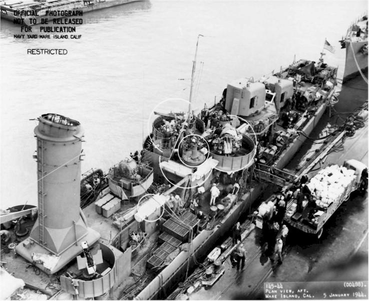 USS McCalla 1944 - Photo: Navsource.org If you intend to use the kits plastic baskets (K44 and K13), with this layout, youll be short by one basket. Ill use the GMM PE baskets and fill them with bits of styrene rod.
STEP 33 - FINISHING TOUCHES |
Now we have a few details left to accomplish: 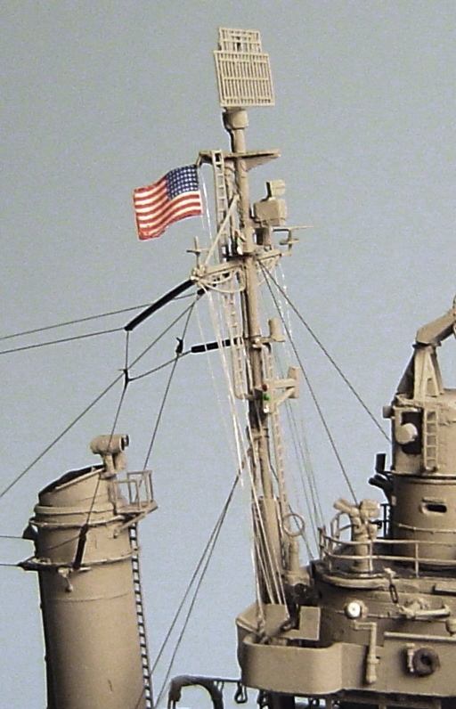 Mainmast Ensign in Tokyo Bay
STEP 34 - SAILORS |
On the famous modeled-for date, Lansdownes crew spent a fair amount of time manning the rails. Ill finish this off by adding about 100 GMM flat-folk in undress whites and a few officers in khakis.
CONCLUSION |
This was a nice build. I will not say that it was not a bit frustrating at times. It certainly was. But, honestly that was mostly my own fault for not researching things more thoroughly before I began. The project took 152 hours (excluding research time which probably exceeded construction time). For that amount of time spent, I am very pleased with what I believe is an excellent (and hopefully accurate) depiction of Lansdowne in 1945. Dragon has recently released or announced several other similar class destroyer kits in 1/350 scale. I cant wait to build all of them just as soon as GMM has developed PE sets for them. | |||||||||||||||||||||||||||||||||||||||||||||||||||||||||||||||||||||||||||||||||||||||||||||||||||||||||||
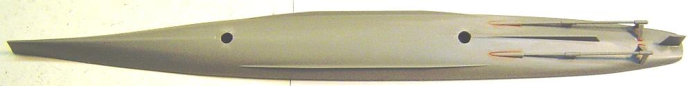
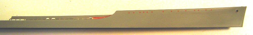
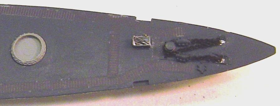
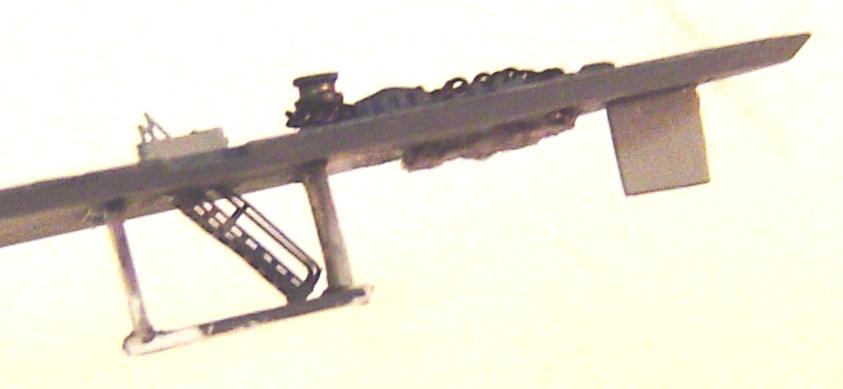
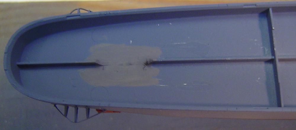

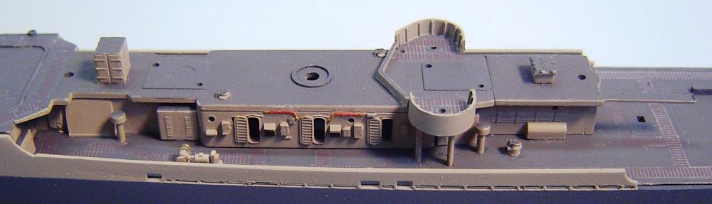
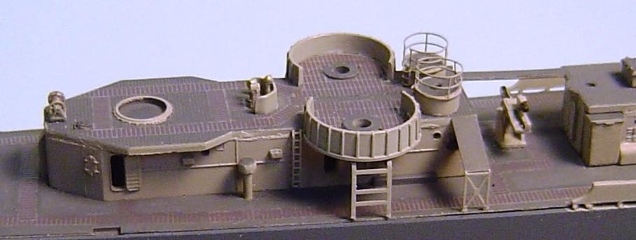
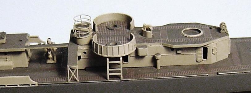
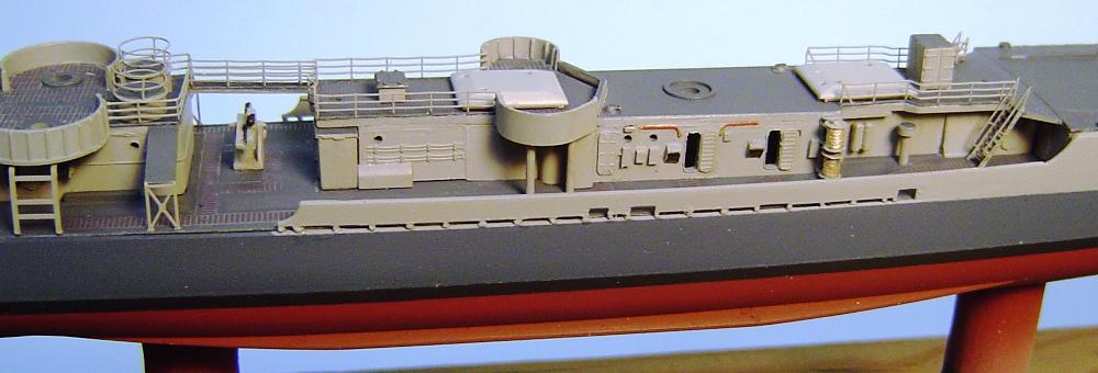
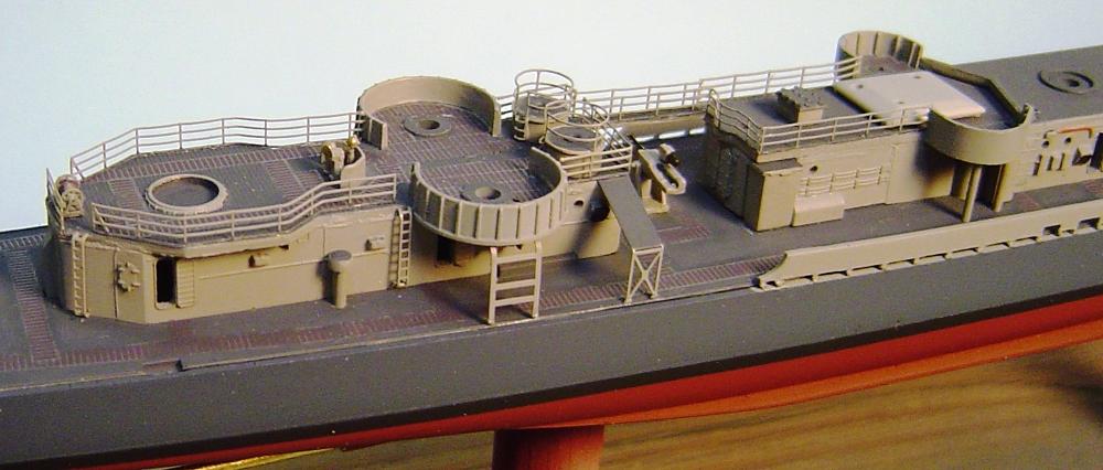
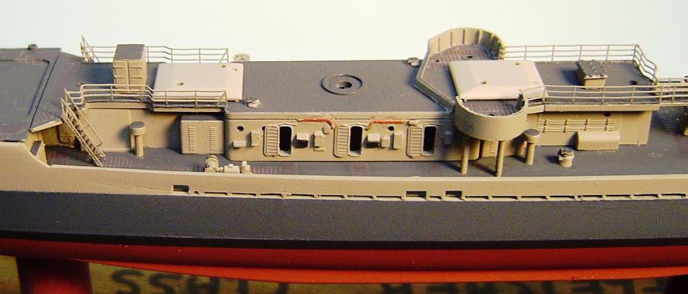
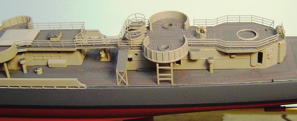
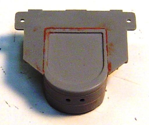
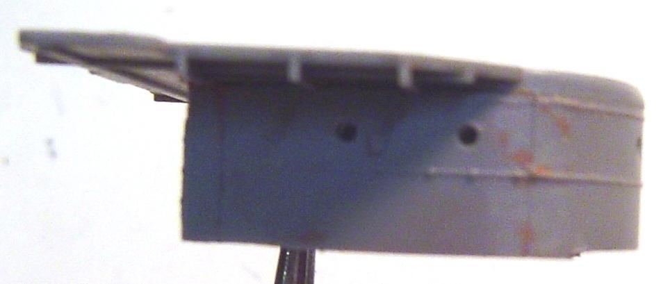
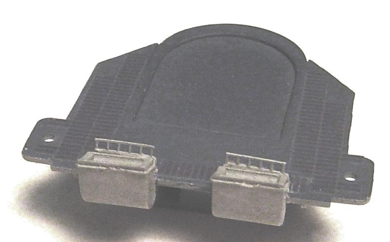
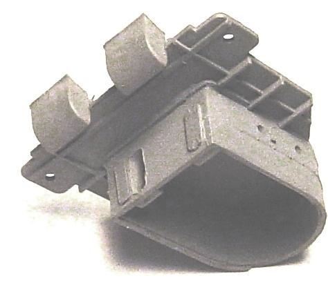
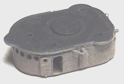
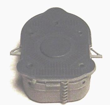
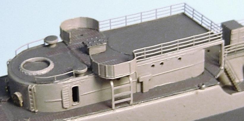
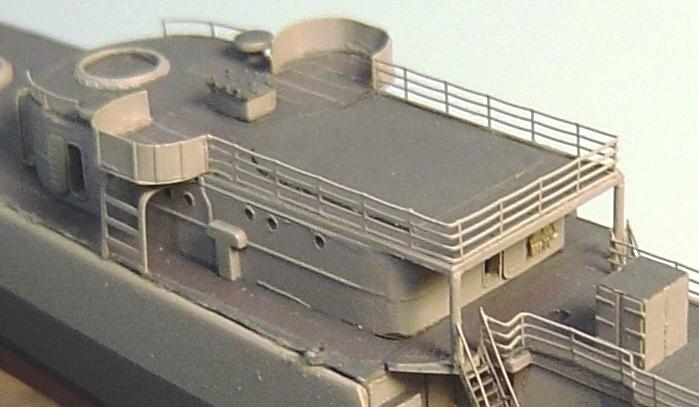
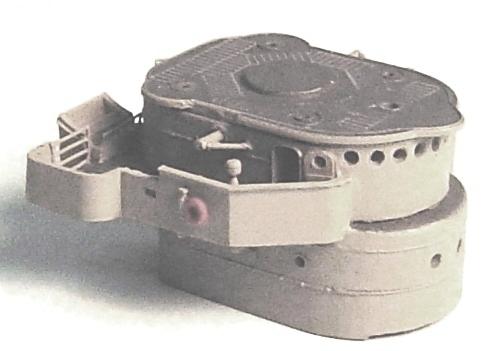
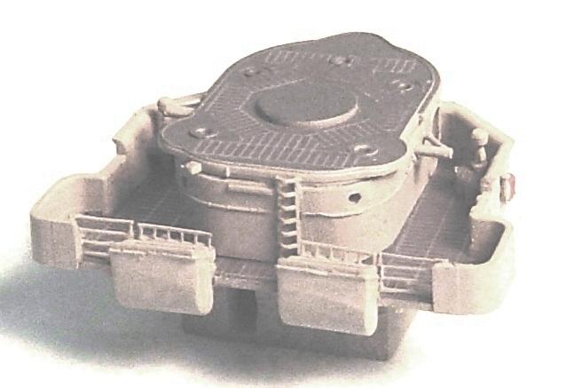
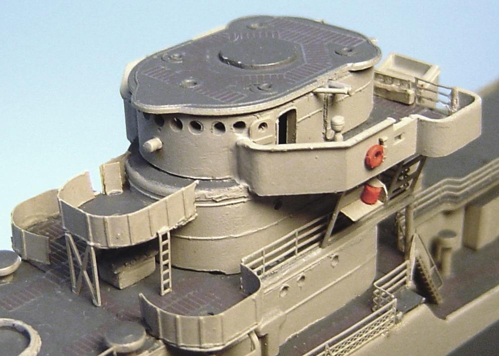
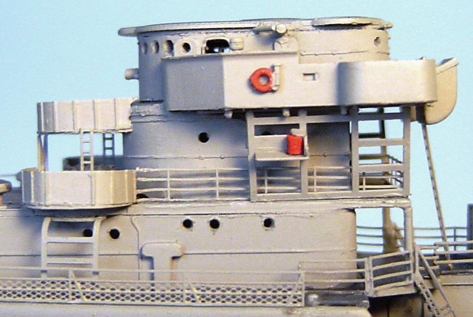
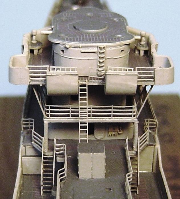
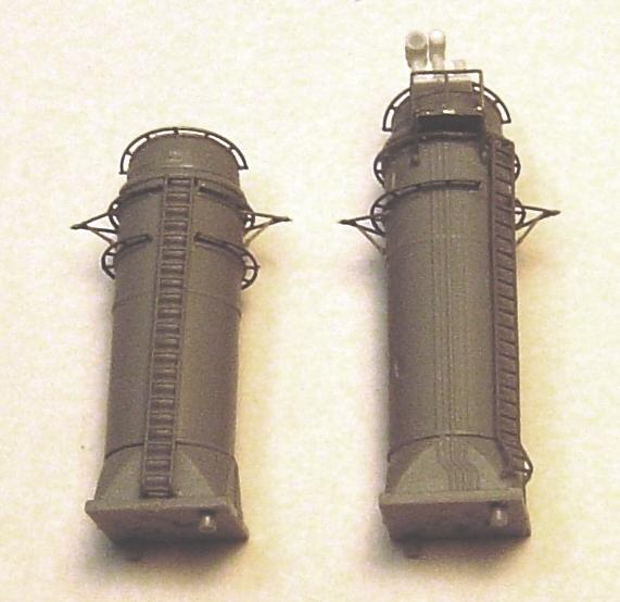
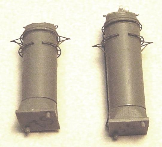
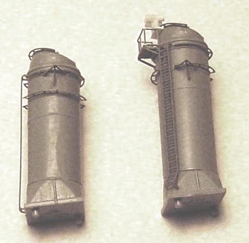
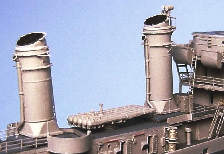
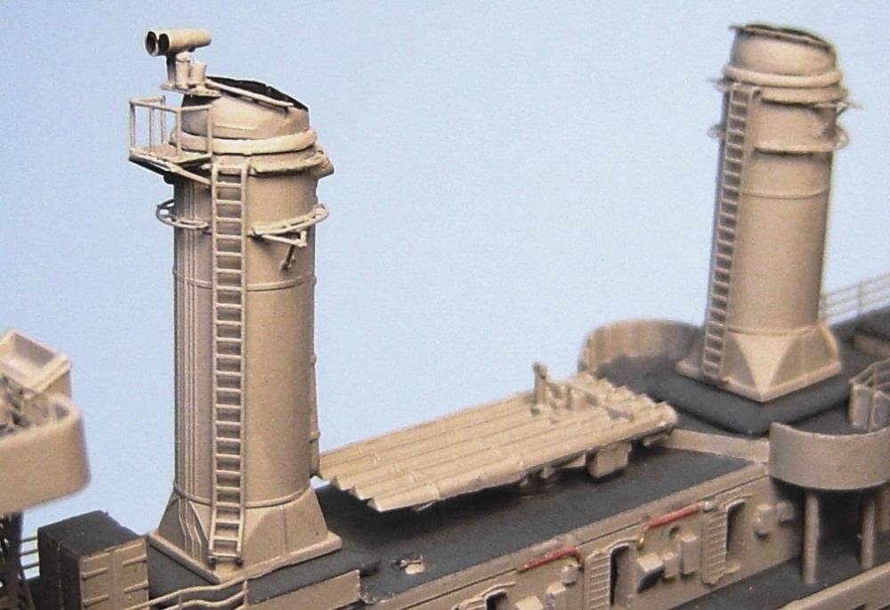
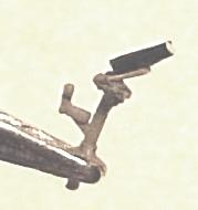
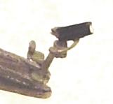
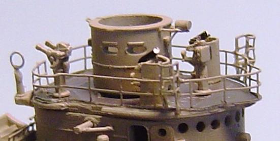
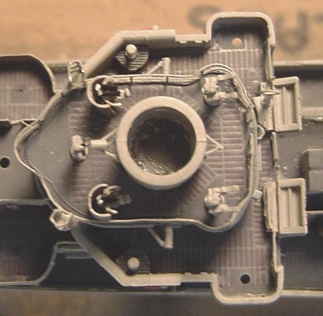
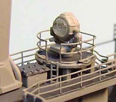
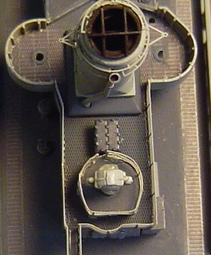
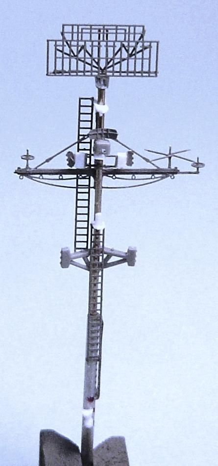
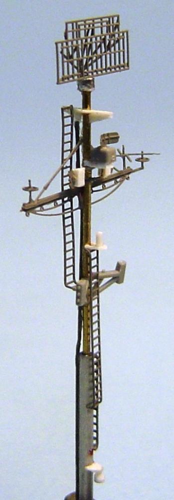
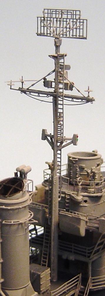
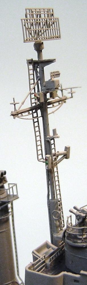
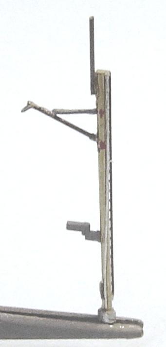
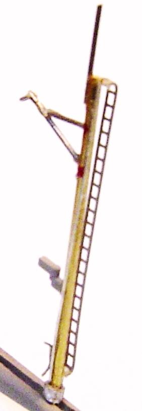
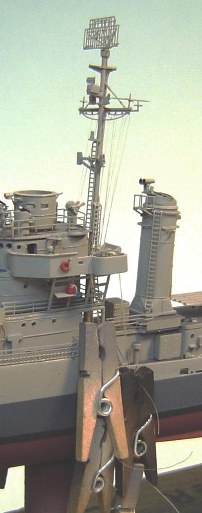
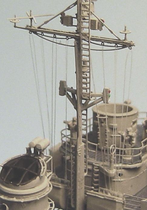
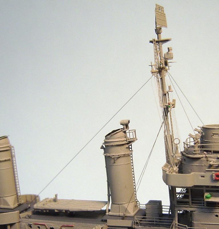
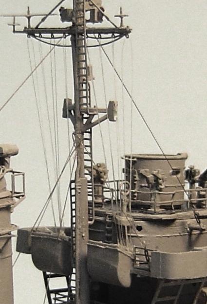
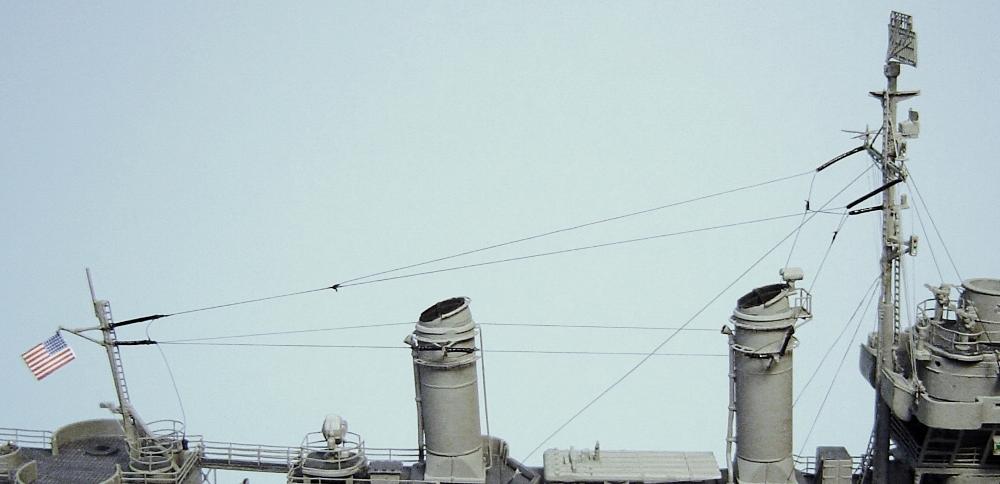
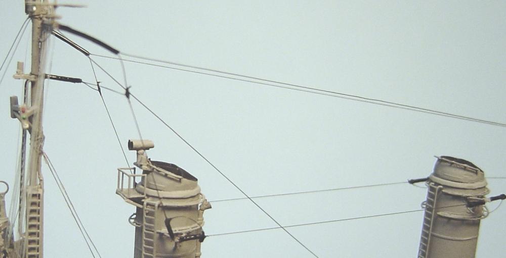
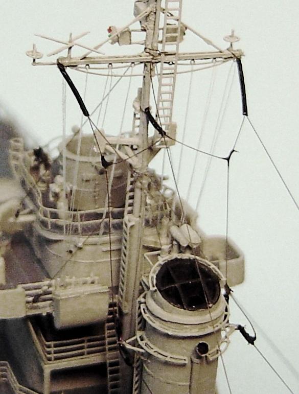
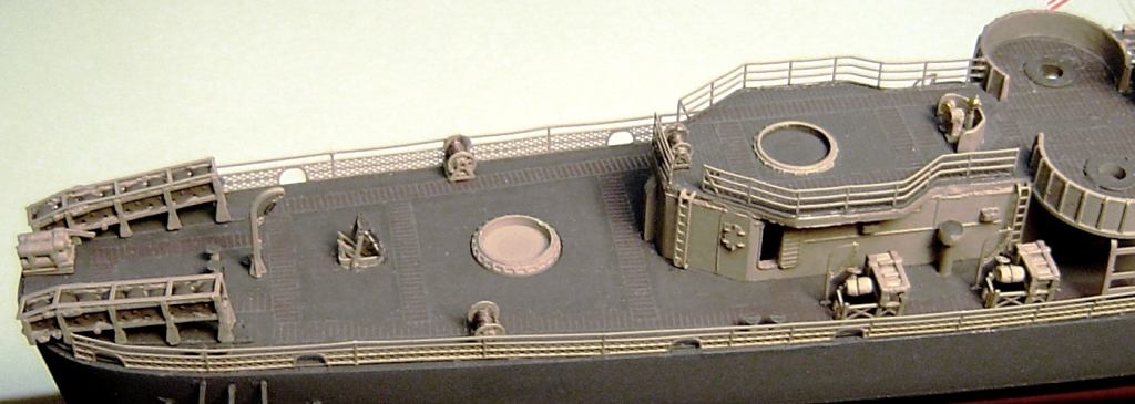
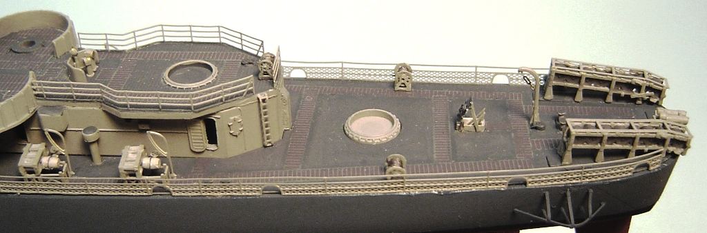
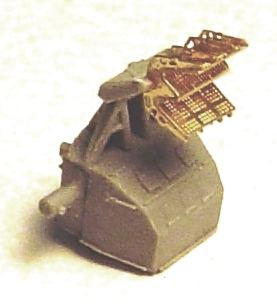
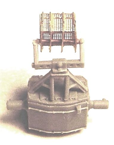

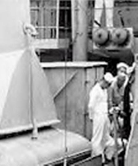
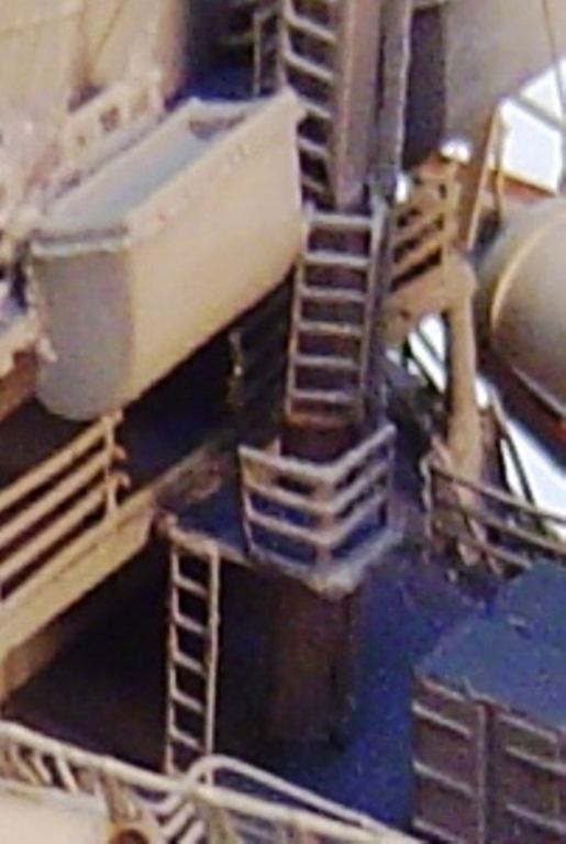
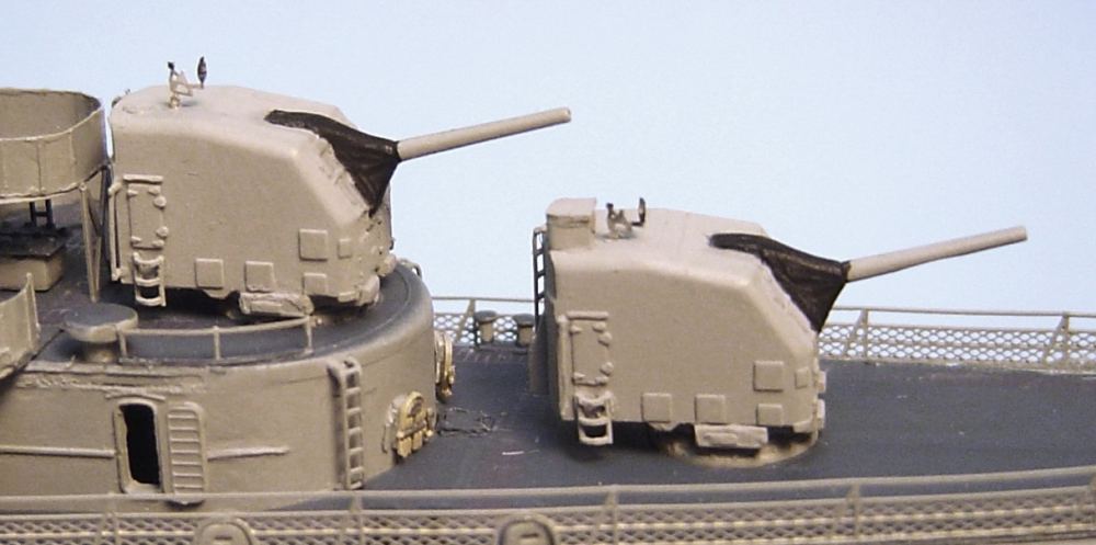
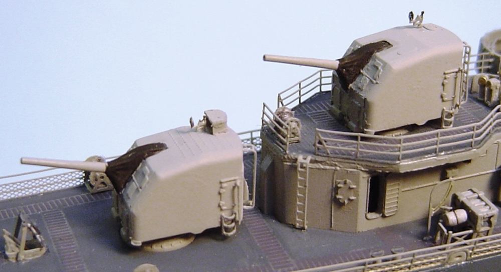
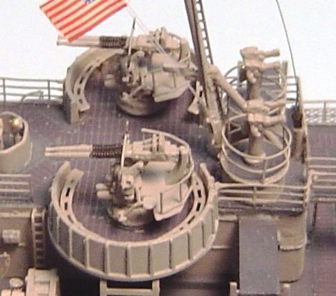
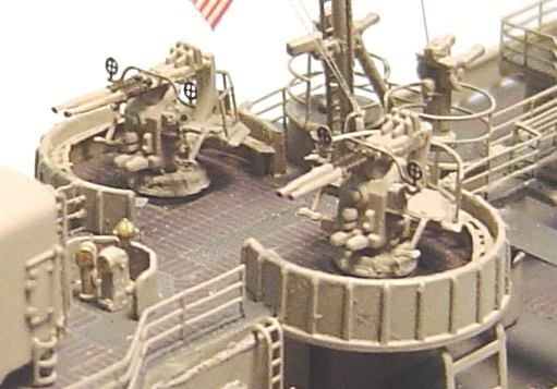
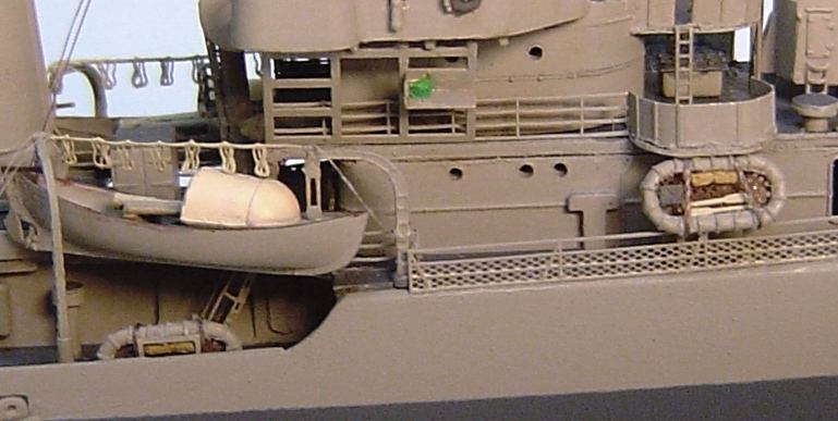
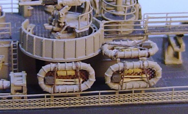
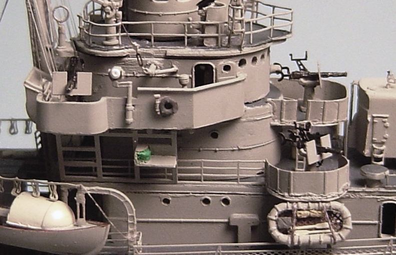
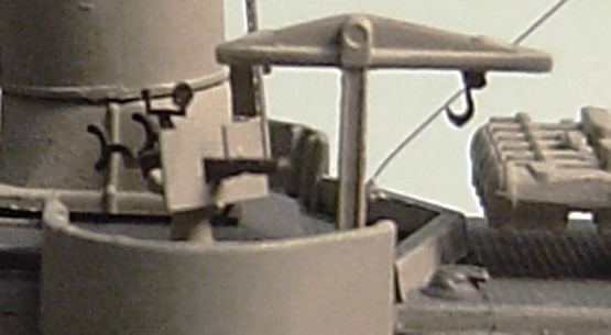
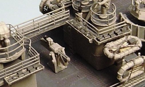
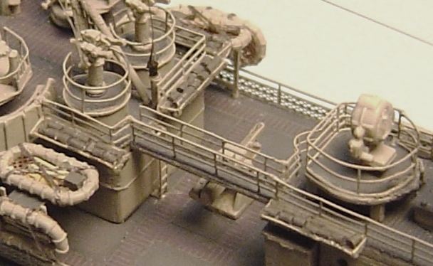
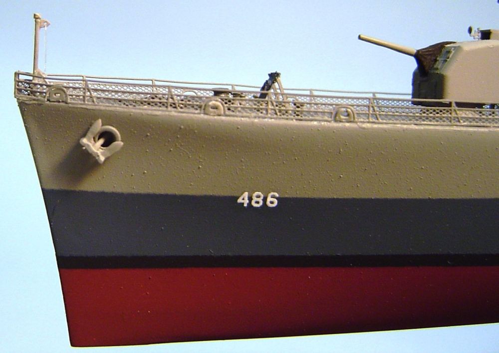
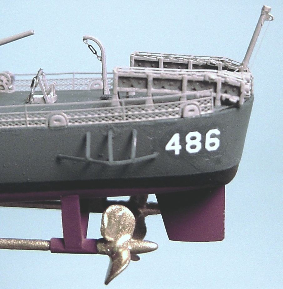

© ModelWarships.com