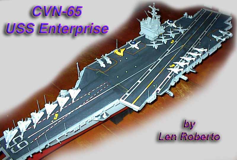
USS Enterprise CVN-65
Part 1
by Len Roberto
back to menu
| HISTORY:
Certain ships need little introduction and the USS Enterprise CVN-65 is such a ship. She is the 8th ship in the US Navy to carry the legendary name of Enterprise and was the worlds first nuclear powered aircraft carrier. Launched 24 September 1960 by Newport News Shipbuilding and Drydock Co., Newport News, Va. and commissioned 25 November 1961, Captain V. P. de Poix, in command. Some quick stats: Specifications
The Big E was one of the first ships to launch strikes in Operation
Enduring Freedom in October of 2001. For much more on the ship and
its rich history, see some of the links listed at the end of the review.
|
|||||||
| THE KIT:
This monster of a kit shocked the modeling world when released in the mid-1980s. It was huge and it was expensive. It portrays the ship as she appeared between the 1979-1982 refit and the 1990-1993 refit. A hangar deck is not included as well as many other details that modelers have been pointing out for years. This is a model that begs for modifications, improvements, and ingenuity. The hull is in two pieces with a bow section that is screwed onto the main hull. The Flight deck is in three pieces and seams need to be addressed. The kit comes with a large display stand and 2 sets of aircraft. Tamiya sells other sets with aircraft not included in the kit to round out the airwing. In order to add much needed detail to my project, I purchased the excellent Gold Medal Models set specifically made for this kit. It supplies exquisite replacement brass parts for flight deck safety netting, radars, ladders, hose reels, railings, and other parts. I also purchased the GMM decal sets for the airwing-an area that can add substantial viewing pleasure to the finished kit. To further this detail, I also purchased Toms Modelworks brass set for the aircraft including gear doors, refueling probes, tail hooks, etc. I wanted to create a hangar deck but my scratchbuilding skills are not up to par to do this right. I will have challenge enough when I get to the aircraft! One final word: I decided to build the kit full hull and to do moderate weathering. Carriers are not clean ships at least on the flight deck. I did not want to go crazy with dirtying up the model- just enough to not make it look like a toy. Also- I read so much on how to correct this for this period and add that for that period that I decided to not try and model the ship as it was for one specific year. I would follow the GMM tips and guide as well as the slew of pictures I had to the best of my ability and not get hung up on whether one part went with another. I am going for a representation of the ship as a whole and not total accuracy. Here we go |
|||||||
| CONSTRUCTION:
Hull & Deck Assembly I started by sitting down at the kitchen table and wrote my own
instructions. Since I would be referring to the kit instructions,
the GMM brass instructions, and a stack of other modelers experiences
building the kit - I thought it would be easier to write a blueprint in
logical steps. I wanted to think about when to add the brass to a
certain assembly and what painting needed to be done in what sequence.
It worked well for me.
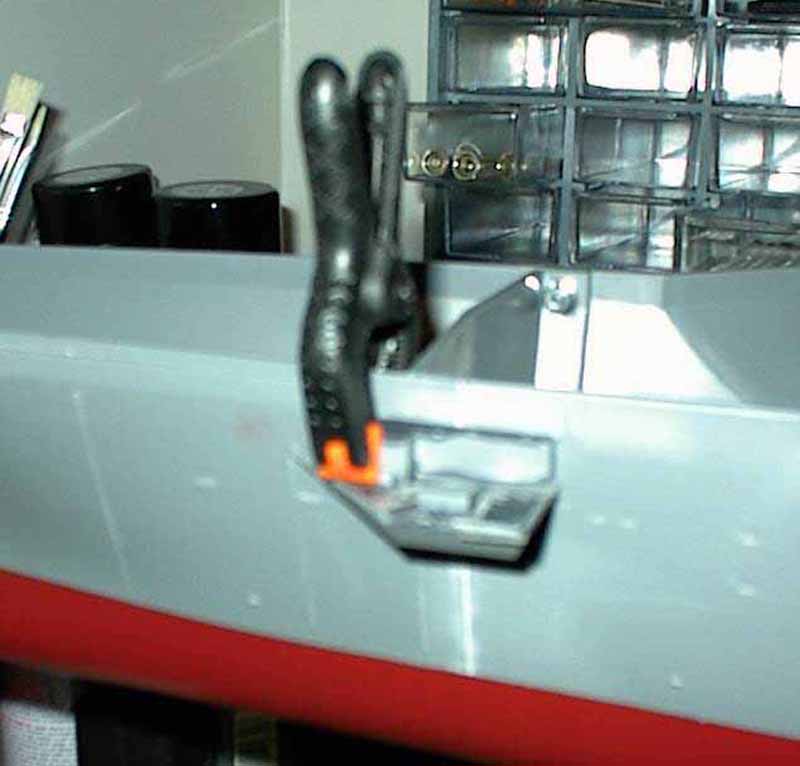
The bow section was glued and screwed to the main hull. Squadron White putty was employed to fill the considerable seam around the hull. Instead of sanding, I used the method illustrated on another webzine where you use nail polish remover to soften the putty and wipe away the excess. The acetone in the nail polish remover allows you to remove excess putty easily. Q-tips were used for this and just a light sanding finished the job. A few spots required repetition of this step but it was cleaner than sanding and saved detail. |
click images
below to enlarge 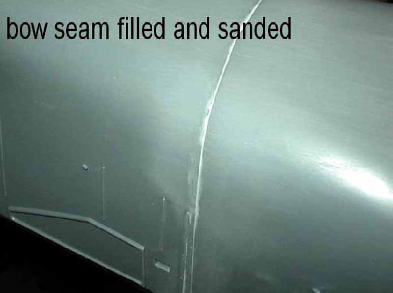 |
||||||
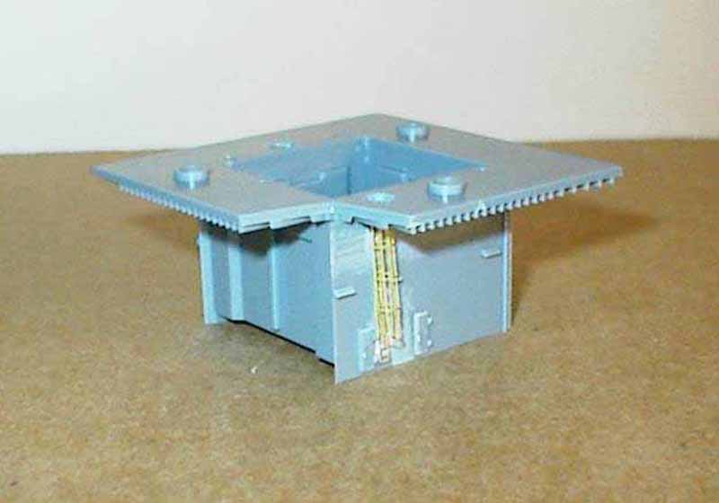
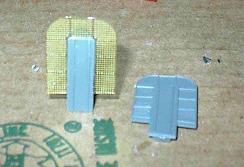
| I then proceeded to attach the hangar doors and the elevator supports. Photo-etched (Ill call the brass PE from here on out) hangar safety rails were attached as per the GMM instructions. The port and starboard bow sponsons were assembled next-one for a Sea Sparrow missile launcher and the other for a CIWS. | |||||||
| Let me take a break here and talk about paint. I read what many other modelers used for paints and not one was the same as another! I needed to find a color for the main grey of the hull and island (Haze Grey) and for the non-skid flight deck and other horizontal surfaces. The non-skid is a very dark grey that varies in shade from one square foot to another on the flight deck. I had many choices but decided to mix a batch consisting of flat black mixed with flat white until I got a nice charcoal grey. I would use sanding and chalk pastels later on to vary the shading. | |||||||
| The reason I tell you this now is because that after the sponsons were assembled- I painted the horizontal areas (the portion where sailors walk) my non-skid color. When dry, I used Scotch clear tape to mask off this color using a sharp blade to clean the mask. Then finally they were attached to their locations on the hull. This procedure was followed for all sponsons and cleat decks around the hull. | 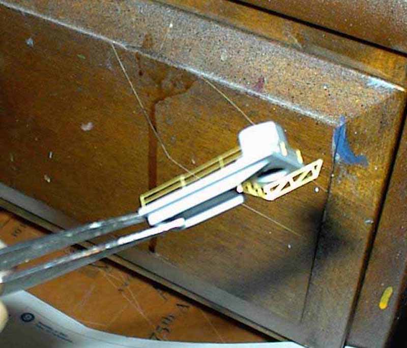 |
||||||
| I then turned to the stern. The SPS-41 platform was treated to two PE supports and a small railing section. The remainder of the stern was assembled with no trouble and a light sanding was needed to smooth the outer piece to the surrounding hull. | 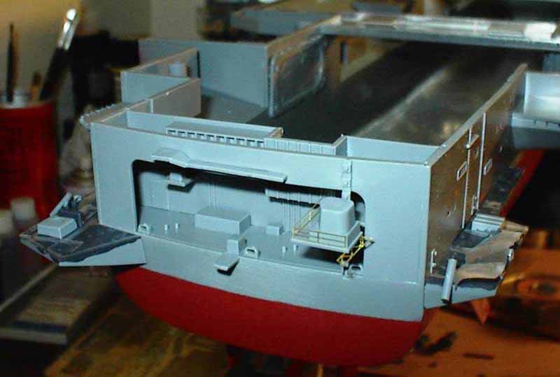 |
||||||
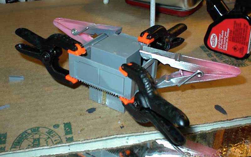
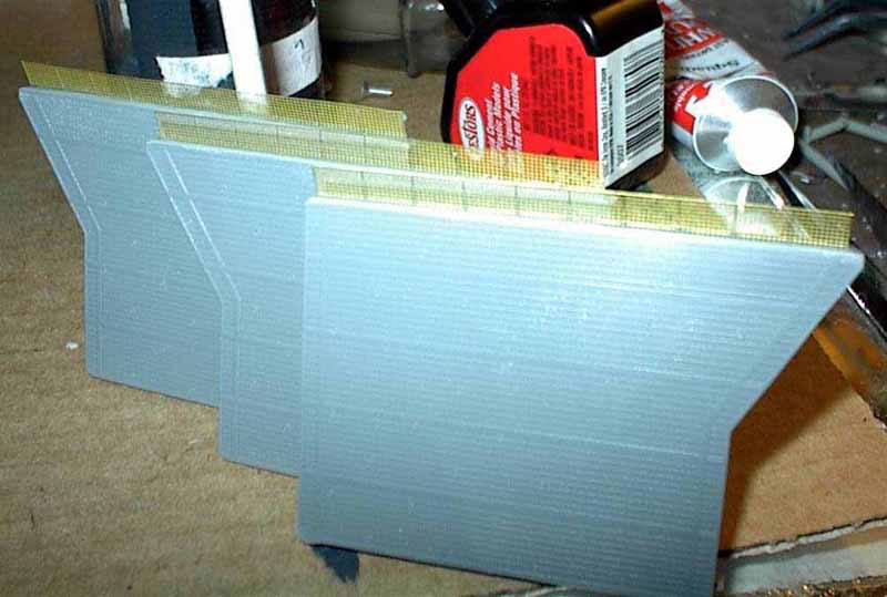
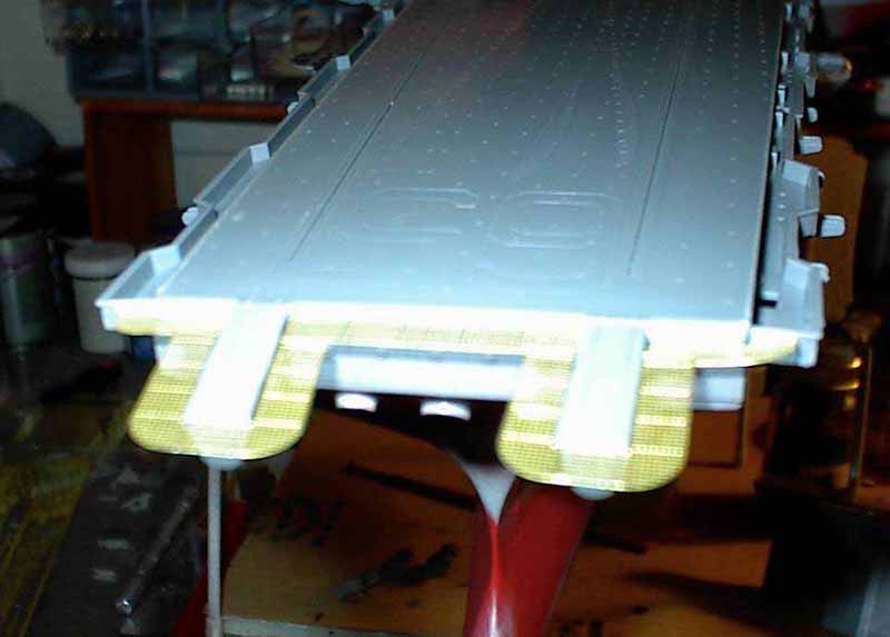
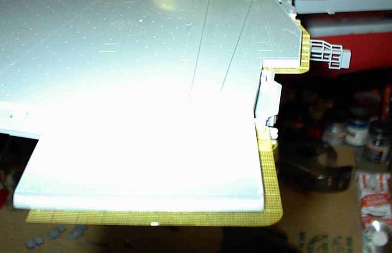
The next major task was to remove the flight deck and elevator
safety netting around the ship. The kits molded plastic netting
really detracts from the overall look and the GMM brass replaces it beautifully.
I used a combination of my sprue cutter, #11 Exacto blades, and a final
sanding to remove the plastic. To give the brass some support, I
used a scribing tool and a ruler to scribe straight line below the deck
level to give the flat brass a ridge to rest against. With CA glue
and this ridge, the brass lined up nicely and was anchored. Check
out the pics of this brass netting all around the model and you can see
how much better these PE parts make the model look.
|
|||||||
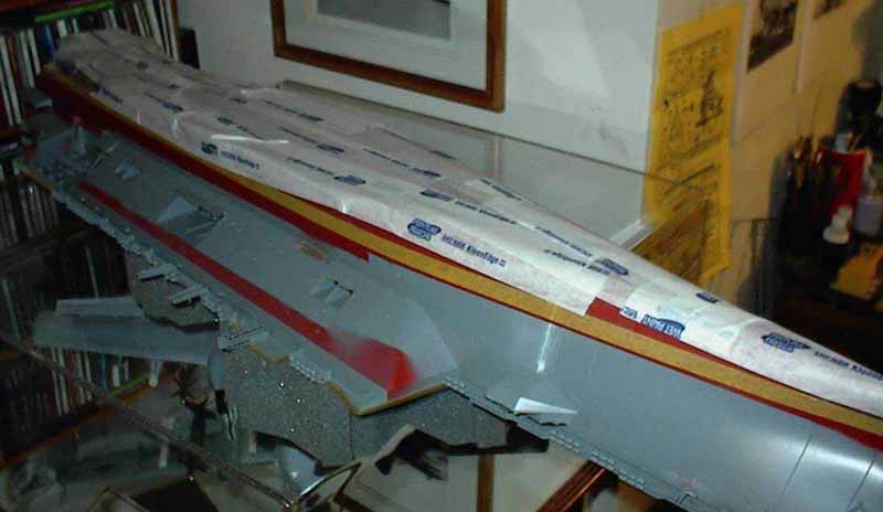
With my attention squarely on the flight
deck, I added the antenna supports and other various under-deck fittings.
I left off the numerous hose reels for now because these will be replaced
with PE and I am saving that tedious chore for the end. Elevators
were placed in their support braces and glued in the up position after
the deck was attached. The flight deck attaches with the bow section
followed by the stern section. The middle deck section fits in notches
and completes this step. I used many clamps and clothespins to secure
these pieces while drying.
|
|||||||
| Island Assembly
The island assembles easily but here is where many plastic parts
are replaced with PE. I clamped the main pieces of the square island
and set to dry. In the meantime, I replaced the plastic safety cage
with a rounded PE part using a brush handle to get the curve. The
four sides of the island fit fairly well with a bit of sanding needed to
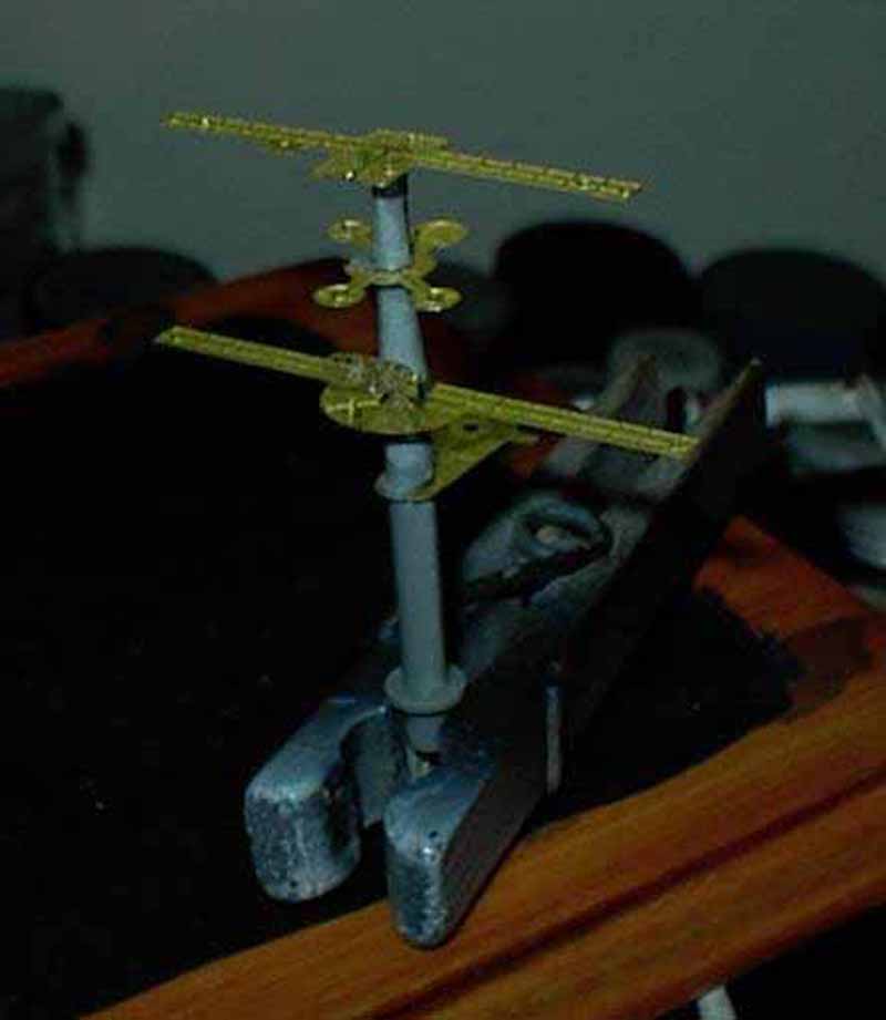
clean up each corner. The radars were replaced with brass and look
infinitely better than the plastic. Much time was spent on the masts.
Each level was replaced by thinner PE parts. The railing added on
these parts was a bit of a challenge to get the right width but they look
great. The various plastic sensors and such were attached carefully
and the final mast assembly was set aside to await painting.
|
 |
||||||
 |
|||||||
 |
|||||||
| There is a fair amount of railing to be added to the island and this was done over the course of a few nights. I measure how many rail sections are needed and also where a bend is needed trying to limit the number of bends or curves to 3-4. More than that gets to be too much for me and I end up losing the correct shape. Using this 3-4 bend method, I got the railing around the island and am very happy with the way it looks-only a few screw-ups and I fixed most of those! | 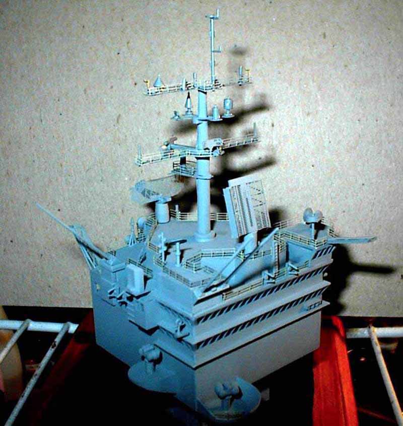 |
||||||
| The mast was carefully glued to the island and I drilled a hole in the bottom of the island, which will not be seen to use as a holding support while painting. Chopsticks have a lot of uses for the modeler for holding fuselages, and islands, while painting! | 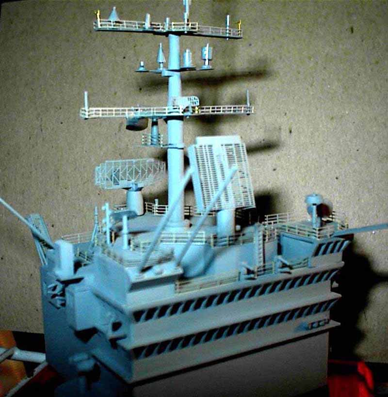 |
||||||
| PAINTING
I already discussed the non-skid color. For the main hull color- haze grey- there are no current mainstream paint manufacturers that have a close match. I have used Tamiya Spray Haze Grey but that has too much of a blue tint. Another modeler suggested Testors Model Master Neutral Grey FS36270 as a good match and I must agree. It looks spot on when airbrushed in thin coats. |
|||||||
| For the bottom hull color, I could find no color photos so I cut a
corner here. I was in Home Depot perusing their spray paint aisle
and noticed a can called Colonial Red made by Rust-Oleum in the American
Accents line of colors. For $4.00- it looked good to me.
I sprayed this color on first and I must say it went on with no runs, no
drips, and no errors. After a day to dry completely, I masked the
red off completely. Next was a thin spray of flat black for the waterline
boot. Another day to dry and this thin line was masked off following
the raised line on the plastic. Then it was a full bottle and half
of the Neutral Grey mixed with thinner in a marathon airbrush session.
I also sprayed the entire island and the brass frets with the unused railing
sections.
When dry, my next step was to brush paint my non-skid color on the flight deck. Why brush painting? My rationale was that after reading numerous descriptions and looking at many color photos of the deck; the color varies from one square foot to another. Oil and exhaust stains, foot traffic, and many other factors contribute to a variety of shades of grey. I decided I would brush on thin coats going heavier in some spots, less in others and would end it with a sanding session. Later on I would use chalk pastels to weather the deck up a bit. |
 |
||||||
| CONSTRUCTION CONTINUES IN
PART 2
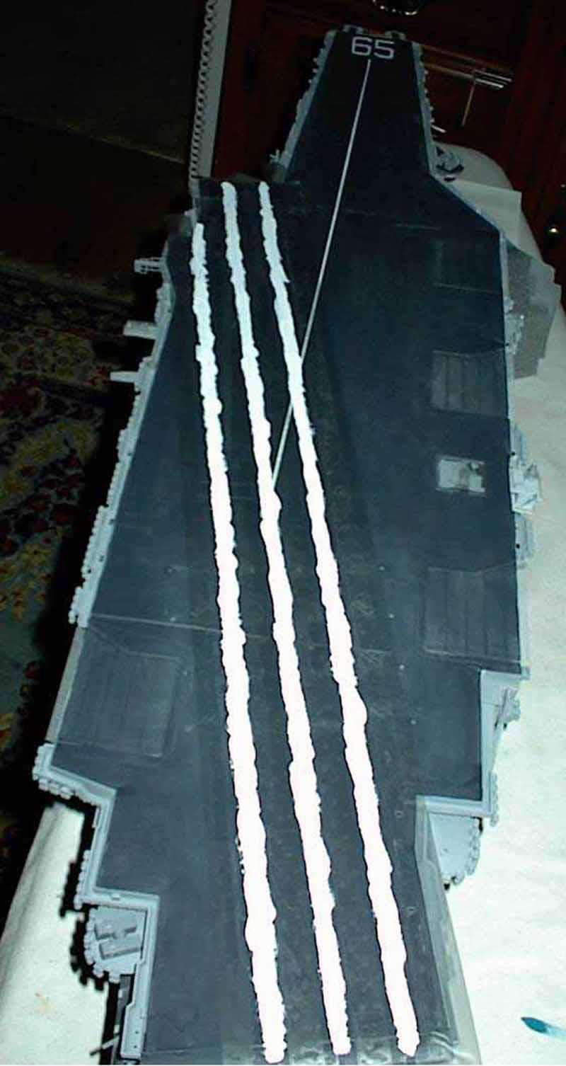
Well, I am in the process of masking and painting the various deck features not included as decals with the kit. This includes the landing stripes, 65 on the bow and other warning stripes. Thanks for reading this far! Part 2 will cover the deck painting, final assembly, the air wing, and final weathering. Until next time happy modeling. |
|||||||
REFERENCES:
|
|||||||

© ModelWarships.com