 |
|
|
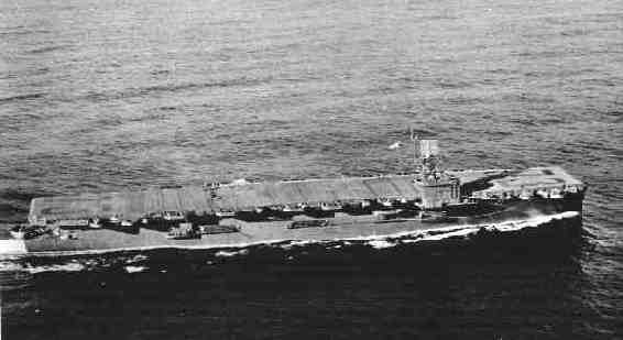
| For many years now, I have had a great interest in the Aircraft Carrier and have always wanted to model one in a large scale. However there are none that are produced in anything larger than 1/250 scale. So I was let to fend for myself if I wanted to have something like that. I didn't want to do a Fleet Carrier in 1/72 because of the size. A ship say of the Essex class in that scale would be about 14 feet long. Although impressive, it would be too large to move around and to work on without having some help and without breaking something in the process. This is when I decided to do an Escort Carrier. Small enough to juggle around, yet large enough to do justice to these great ships. I proceeded to acquire blueprints for the project from the Floating Drydock. When I received them I almost fell off my chair! I did not realize how large an Escort Carrier really was in 1/72 scale. I must admit that I was somewhat intimidated by all this and was considering dropping the whole idea. A daunting project at best. After looking over the blueprints several times I decided that I would proceed after all. The first order of business was to figure out the construction sequence, I.E. what goes where and when and what material to use for any given area. After this was somewhat determined, I proceeded with construction. Now on to the photos! | |||
|
|
Click images
 |
to enlarge
 |
|
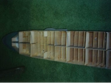
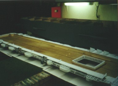
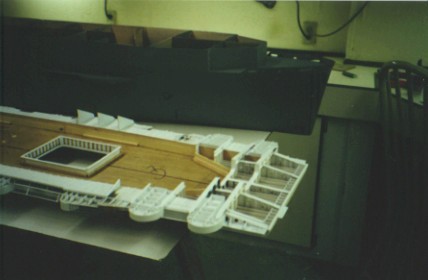
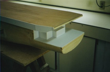
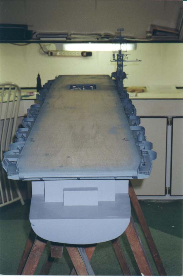
| In these photos you can see that I have added the underdeck bracing, gun tubs, etc. All these parts were fabricated from sheet and strip styrene in various thickness' and width. Some I purchased already cut, others I did myself. Note that the hull fits snugly inside the flight deck structure without moving. This way it can be readily removed for battery changes or to repair any malfunctions. Note the fwd. elevator opening. The elevator does operate but the drive components have not yet been added. | 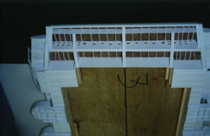 |
 |
 |
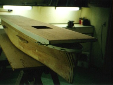
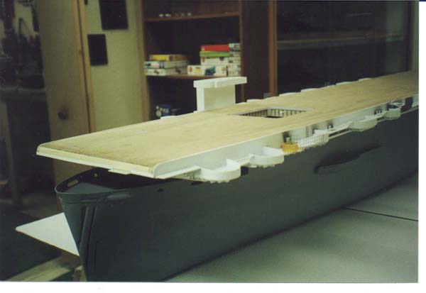
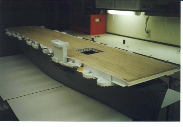
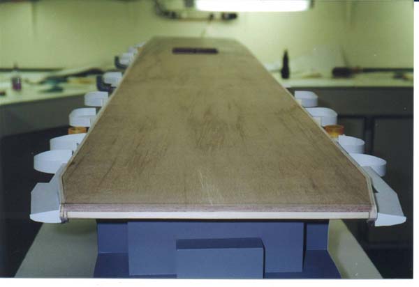
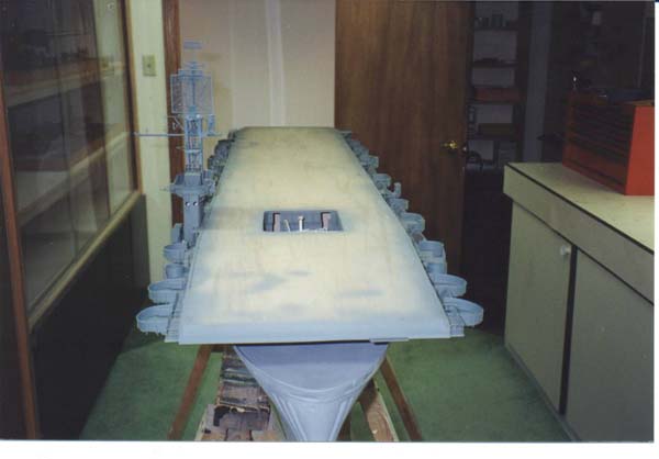
| Here you can see the flight deck sitting on the hull. In these shots the gun tubs and other items have not yet been added. Hull has not been primed yet but the resin has been applied. Any thing that is white is sheet styrene. | 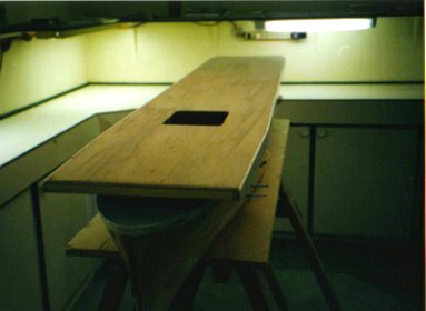 |
 |
 |
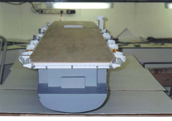
| In these shots you can see I have started work on the Gallery deck areas. The island has been roughed in and is on the deck but not permanently attached yet. Note the picture looking fwd. and up at the ship. You can see that there are gaps in the hull planking. These will be filled in later. I'll use auto body filler to shape everything correctly along the entire length of the hull structure as needed. Note the parts that are orange in color. These are the rings that go around the 40 mm gun directors. I made them from a R/X pill bottle. It was the right diameter I needed so all I had to do was to cut to correct height. I point this out because when you are scratch building you have to look around for things that you may be able to use. It could be anything. That's part of the fun of it all! | 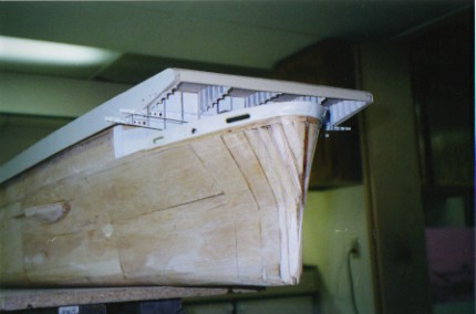 |
 |
 |
| More shots of the flight deck areas | 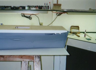 |
 |
 |
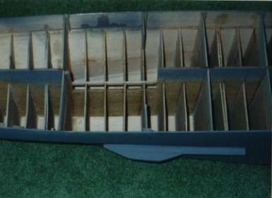
| Here we have the under deck bracing almost completed except for painting. There are over two thousand individual parts that go to this bracing structure around the entire length of the ship. This process was somewhat time consuming but the end result is pleasing I believe. I again used a lot of styrene. | 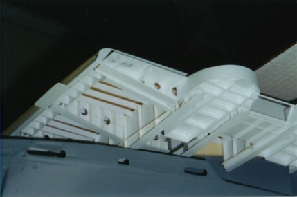 |
 |
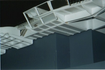 |
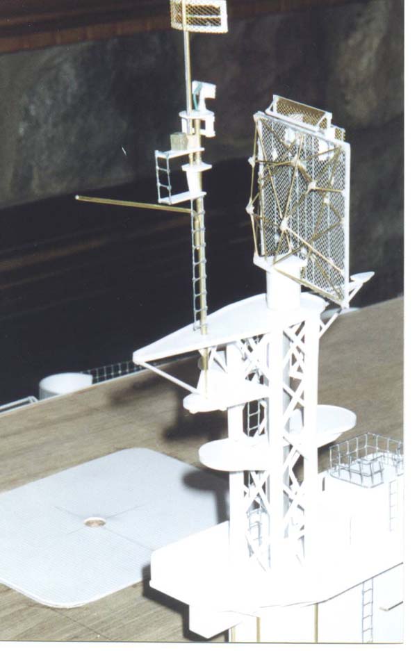
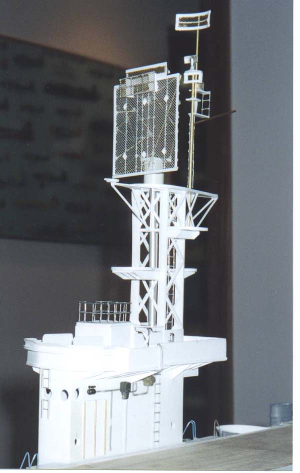
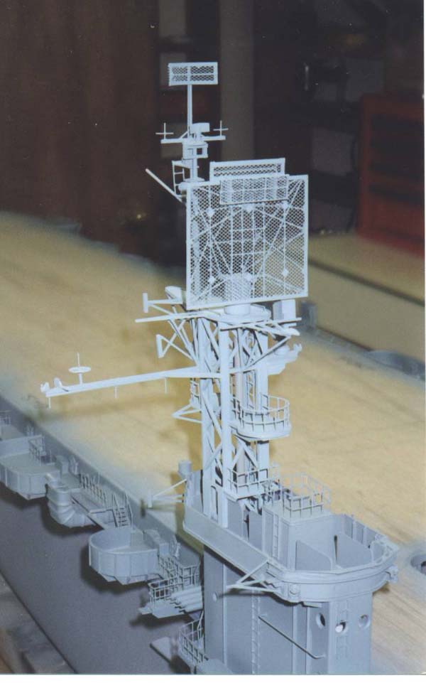
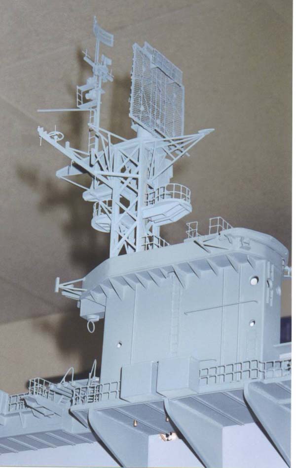
| Some nice shots of the island/tower radar assemblies. Here I used a combination of styrene in various configurations, brass wire, brass mesh screen and bridal veil! Yes, bridal veil. I used this for the large SK radar screen and for the safety netting along the edges of the Gallery deck. You can buy a ton of this stuff at a fabric store and it has many uses and is real cheap. I bought enough to do a hundred models for about $2.00. Note details on the island structure. Some of these parts came from 1/35 armor models, leftover from a diorama I had built previously. Also note the railings on the inclined ladders. These we made from telephone wire, which is another great material and has many uses. It's very thin and flexible and CA sticks to it almost instantly. You can buy a ton of this cheap too. The SK radar assembly. is operational also via a gearbox with a vertical drive shaft mounted inside the island structure. | 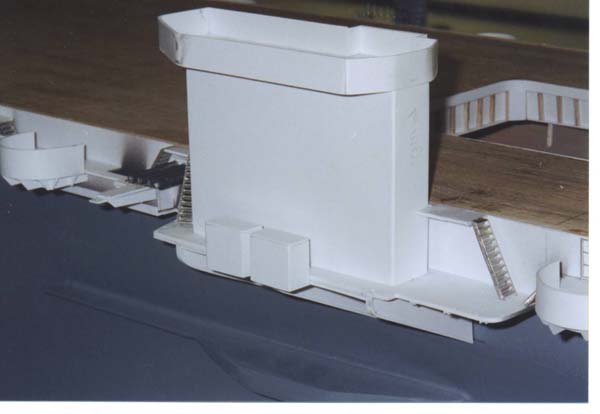 |
 |
 |
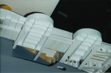
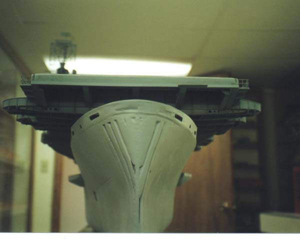
| Here we have shots of the smokestacks, the fwd. elevator and a bow shot. I'll start with the stacks. These are fabricated from sheet balsa and telephone wire. I made an L shaped configuration from the balsa sheet with a gusset added to the inside corner. I then sanded the balsa to shape the radius'. I then added the telephone wire to form the divisions of the sections of the stack. Finally, I dremeled out the opening. These go rather quick once you make one, the other three are the same. In the picture of the bow you can see where the hull needs work. As I wrote earlier, all the gaps and imperfections will be cured using auto body filler, also known as bondo. Doing this is kind of like body work on a car only on a smaller scale. The filler works great for shaping things but you must form before it is completely dry. This way it is much easier to sand and shape to rough proportions, then continue with final sanding and finishing. | 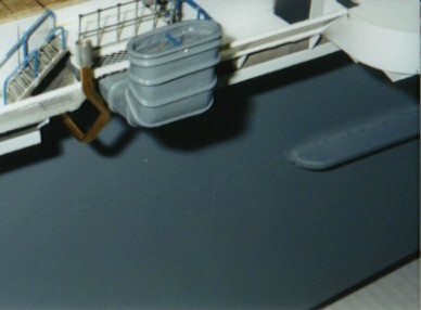 |
 |
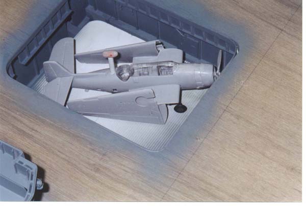 |
| Finally we have the fwd. elevator. Note the walls of the shaft. This was done again using styrene and leftover parts. The aircraft is a TBM-1 avenger torpedo bomber. Note the radome just behind the ball turret. This is not accurate as no T.M.'s carried this type of radar. This was the only way to hide the screw drive shaft. The drive unit to make the elevator go up and down is a high speed gearbox coupled to a 4/40 threaded rod. This rod is then screwed to a 4/40 blind nut mounted in the center of the elevator platform. As the elevator makes it's down travel, the threaded rod comes up through it and into the airplane ending up inside this radome assy. When completed it should look pretty convincing for the most part. I tried to set things up on this working elevator as simple as possible. I'm sure there are other ways to do it but my aim was only to show some movement. Works pretty good after much trial and error and 3 burnt motors! The other details of operation would take up too much space in this presentation, so I've only given a brief description. | |||
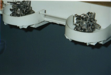
| Here a some pics. of the guns. These are from HR Products and are cast metal. They require some clean up and detailing but are pretty accurate for the most part. Note that the gun tubs are not yet detailed out, still roughed in. They will look much better when I'm done with them!! | 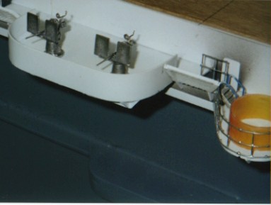 |
 |
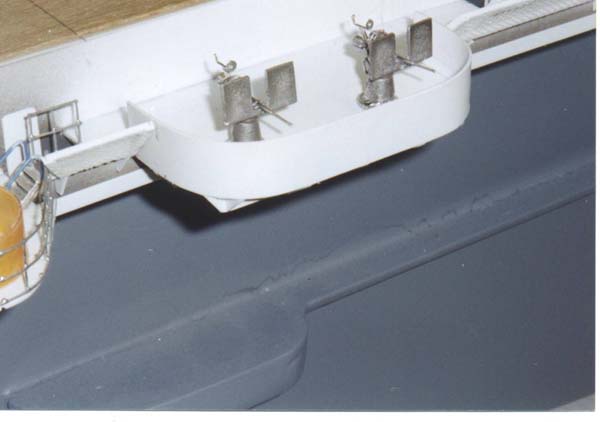 |
| Here you can see the added details to the gun tubs after painting. All railing on the ship was fabricated from galvanized wire mesh. Also are fore and aft views | 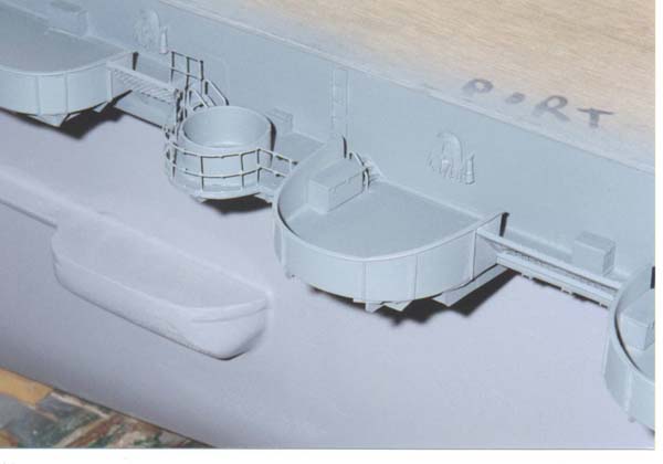 |
 |
 |
| In these shots you can see that the island/tower/radar assemblies. are mostly completed. I have a few more details to add. | 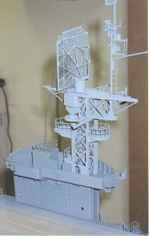 |
 |
 |
| Epilog: Well, I hope this gives everyone an
idea of where things are at. I've been on the project for almost ten months
and hope to be completed by mid August of this year if all goes well and
I don't drop it!! I must give many thanks to this Website for the opportunity
to share this with everyone. More photos to come as I proceed with things
so stay tuned.
Any questions anyone has or if I can be of any assistance, please feel free to e-mail me at bjsww@earthlink.net. Bill Waldorf
|
|||

© ModelWarships.com