|
| page 1 of 2 |
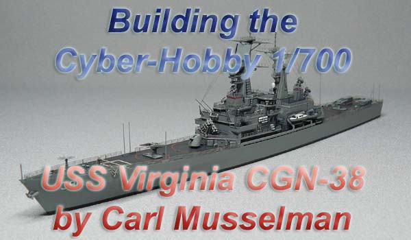
| I was flattered when Tim Dike asked me
to conduct a Build-Up Review of this new DRAGON plastic model kit.
As my first, such venture I hope that it is of a proper format and from
an appropriate aspect.
Instead of viewing this kit from a point of view of comparing anatomical features of the model and of the actual ship, I have chosen to take the point of view of a modeler with no outside reference photos, drawings, or knowledge of the actual USS Virginia CGN-38 or other ships of the same class. Although this method and point of view is difficult, for me, to maintain
throughout the build, I have referred to photos of the USS Virginia and
I have modified my model to make it a little more correct; e.g. paint colors,
the SPS-40 radar, and two additional inclined ladders, etc. This
is not a true out-of-the-box build but, it is not a strict portrayal of
the real ship at any particular period in time, either.
|
||||||
 Overall,
this new kit by DRAGON is of a very, welcomed subject and contains several
nicely detailed features including some optional photo-etched pieces.
Although I have built my model as a waterline model, the option for a waterline
or full-hull model, like this kit has, should be a standard set for all
1/700 ship models, I feel. Overall,
this new kit by DRAGON is of a very, welcomed subject and contains several
nicely detailed features including some optional photo-etched pieces.
Although I have built my model as a waterline model, the option for a waterline
or full-hull model, like this kit has, should be a standard set for all
1/700 ship models, I feel.
The mold of this kit is of good quality however, in my kit, Sprue D appears to have had an offset mold. The two sides (top and bottom / left and right sides) of each part dont exactly match up and this has led to exaggerated mold seams and flashing. This same effect is slightly present on Sprue B, as well. Luckily I have extra Sprue D equipment sets from other kits that I can use parts from. In general, Im happy with the quality and assembly of this kit but, most of my comments concern confusing inconsistencies in the instructions. A beginner modeler could find the instructions frustrating and could make some mistakes if the instructions are followed verbatim. Step 1 (Fore Mast) Although the SPS-48 radar array is adequate, I would have expected a similar piece like that in the DRAGON USS Chandler DD-996 (Kidd Class) kit which provided a photo-etched piece for the framing on the rear of the array. |
||||||
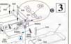
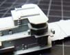
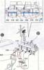
| Step 2 (Forward Superstructure)
I recommend not attaching Parts C28 and C29 (antenna trunks) until you are ready to attach Part A19 from Step 3. Parts C28 and C29 must line up with notches in Part A19. According to the instructions and guide mark on the model, the Phalanx CIWS (Parts D20) should be positioned flush with the edge of the deck. On the real ship, these were set back from the decks edge. I chose to follow the intent of the instructions. |
 |
|||||
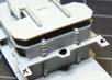
| Step 3 (Further Forward Superstructure Assembly)
O2 deck platform Part A19 has two notches on the forward edge which may need to be enlarged in order for Parts C28 and C29 to fit within. |
 |
|||||
 |
||||||
| Part A19 has molded-in signal flag bags which are oriented horizontally and should be oriented vertically. I removed the molded-on bags and replaced them with the signal flag bags on the extra parts Sprue D included in the kit. This must be a really embarrassing mistake for DRAGON. If you intend to use PE railings, I recommend attaching the replacement signal flag bags after you position and attach the railings on the deck section where the flag bags are located. | 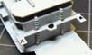 |
|||||
 |
||||||
 |
||||||
| Part C63 (forward superstructure, port side main deck bulkhead piece should be attached when youre ready to attach Part A18 form Step 4. These two parts hook into each other under the O1 deck and both need to align with the guiding edge line on the main deck. There is no guiding edge line beneath the O1 deck to line up Part C63. | 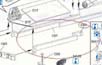 |
|||||
 |
||||||
 |
||||||
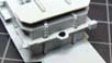
| Although these are nicely detailed pieces, the instructions to attach the port side life raft canister racks (Parts B2 and B3) show up in both Step 3 and Step 5. In Step 3, the instructions indicate to place the port side life raft canister rack (Part B2) into the wrong hole in the deck but, it shows up in the correct place in Step 5. | 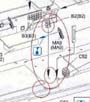 |
|||||
 |
||||||
| The instructions show three saluting guns (Part B36) but, one of them
has no attachment direction arrow. This third one appears to be a
stray image and is not intended to be attached nor is a third gun provided.
I had to putty some deck-to-bulkhead seams on the forward superstructure. |
 |
|||||
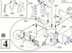
| Step 4 (Aft Mast and Superstructure)
Both plastic and photo-etched SPS-49 optional parts included with the kit are really anatomically incorrect. And in the reference photos that I have of the real ship dating from 1976 through 1992 (StillMotionsPhotographics.com DVD included) I have not seen the USS Virginia, herself, with an SPS-49 radar, just with an SPS-40 radar. I have used the SPS-40 from the Gold Medal Models 1/700 Naval Ship Photo-Etch Set. |
 |
|||||
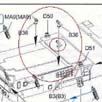
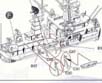
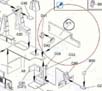
| Step 6 & 7 (Small Boats and Davits)
Although there is a really nice insert diagram of where the small boats and their davits are supposed to be positioned on the port side, all of the small boat davits (C36, C34, C32 port side; and C30, C31, C47, C48 starboard side) and port side platform C18 should probably be attached after the superstructure assembly is attached to the main deck rather than attached to the superstructure assembly first, as shown in the instructions. The davits need to line up with holes on the port and starboard side edges of the main deck. I preferred to let the holes in the main deck be my guide to the alignment of the davits proper positions. |
 |
|||||
 |
||||||
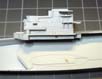
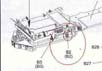
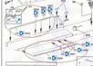
| Step 8 (Hull and Main Deck)
Bulwark pieces C3, C5, C6, C8 (ports side) and C2, C4, C7, C9 (starboard side) should be attached after the small boat davits have been attached to the main deck. The davits provide a guide as to the proper positioning of the bulwark pieces. Even after that, I found that I had to alternate pieces C3 and C5 and clip them shorter to fit between the davits. |
 |
|||||
| Anchor hawse pieces A7 and A6 are nice replicas of the real thing when compared to other kits that I have been built with a bow two-fluke anchor and a danforth anchor. But, I dont quite understand why they couldnt have been molded into the hull rather than as separate pieces. | 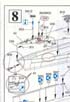 |
|||||
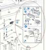
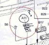
| Among the separate equipment pieces on the forecastle,
Parts B42, B35 are shown in place but, are not identified by their numbers
in the instructions. And Part B35 appears in the instructions image
a little forward than where it should be.
Also on the forecastle, in the instructions, is a Part C42, which appears to be an anchor brake, doesnt exist on the C sprue. I merely inserted a piece of brass rod in the hole intended for this Part C42. The actual Part C42 was used on the forward superstructure and is a platform extending outboard near the bridge. There is a Part B40 which looks like a hand wheel with no shaft but, is not addressed in the instructions, anywhere, and is not blued out in the sprue inventory images. This could be part of an anchor brake but, there is no part that looks like its shaft. And there should be two anchor / capstan brakes instead of just the one. Part B40 also looks a little too, large for this scale, as well. Gun turrets B29 are much nicer than previous versions (DRAGON SKYWAVE/PIT-ROAD, TRUMPETER) that Ive had to use in the past. I didnt have to putty fill the rear of them like those on other extra equipment sprues. The aft SAM launcher subassembly is annotated as A11 in the instructions, which is rather confusing when it is built from Parts B1, B10, B15, B16, and B19. The sub-step for the SAM subassembly indicates two paint colors (H11/62 & H25/34) but, these codes are not referenced in the paint color table. |
 |
|||||
 |
||||||
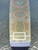
| Decals
In order to allow for attaching PE railings at the main decks edge and by using Part B18, (Tomahawk ABL foundation) as a guide, I found that the instructed positioning of the red warning line markings for the ABLs wont align with the guide pin holes for the Part B18. I have clipped off the guide pins on the bottom of B18 and centered it (port and starboard) within the warning line decal. |
 |
|||||
| General Comments
The chocks/fairleads are molded onto the hull section and are a nice detail unless you plan to use photo-etched railings like I have. The chocks/fairleads are in the way of placing the railings flush up to the decks edge. I dont like having to cut the bottom rail(s) of the PE pieces. The chocks/fairleads would probably interfere with the stanchions of the PE rails, anyway. So, I clipped off all of the chocks on my model. The molded-in life safety rings are too, large and not to scale. I found the photo-etched inclined ladders (4 are supplied by the kit) to be too, wide for my liking so, I replaced them with those from Gold Medal Models and added two more missing inclined ladders for a total of 6. At least there were no plastic or molded-in inclined ladders included with the kit. I used Model Master Acrylic Paints: Neutral Gray, Engine Gray, Gloss Clear Coat, Flat Clear Coat, Flat Black, and Flat White. For the main deck finish, I first applied the Engine Gray and then used a brushing of black pastel chalk to darken it. The railings are by LArsenal. The rigging is Caenis 20 denier
thread. The SPS-40 radar is from Gold Medal Models.
|
||||||
More
of Carl Musselman 's work.
Updated 2010

© ModelWarships.com