A build up review of the 1/700 Imperial Hobby Productions kit
by Martin J Quinn
A build up review of the 1/700 Imperial Hobby Productions kit
by Martin J Quinn
I started as I always do, by checking out the in-box review here on ModelWarships. Then, I started looking for references. Outside of the aforementioned Gibbons book, there aren't many, given that these beauties were never finished as originally designed. However, the fact that they were never completed worked in my favor, because it gave me a little leeway in completing the model.
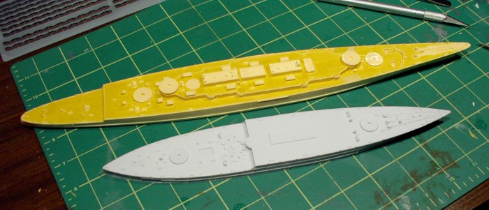
After washing the model and parts in warm soapy water, I airbrushed the deck with teak from the White Ensign Models paint line. I then started to mask the deck in preparation for painting the overall Standard Gray color, when I noticed the paint was peeling off the deck. So, I rubbed down the hull with acetone and gave the model another wash in soapy water, then re-sprayed the deck.
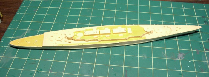
Masking the hull |
Partially masked deck with dry-fitted pieces |
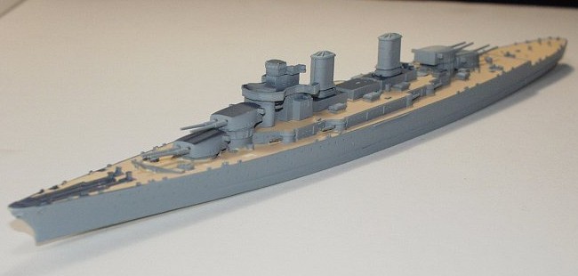
Sara was BIG - Waveline USS Maryland along side for scale |
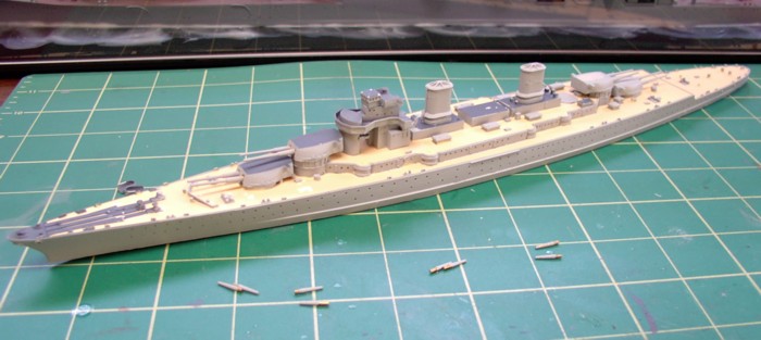
Sara before the #5 Standard Gray was airbrushed on |
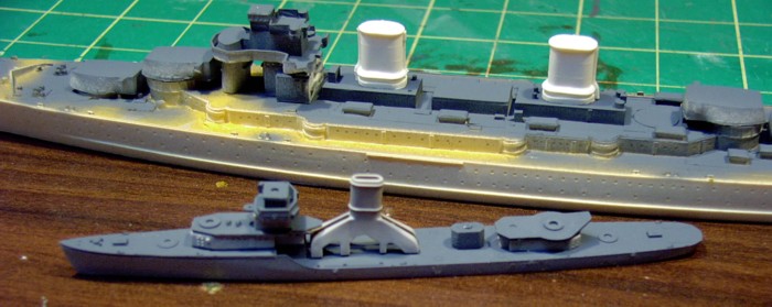
Midship Models DD USS Benham alongside Sara |
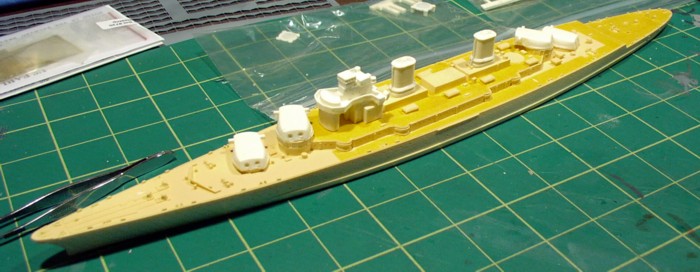
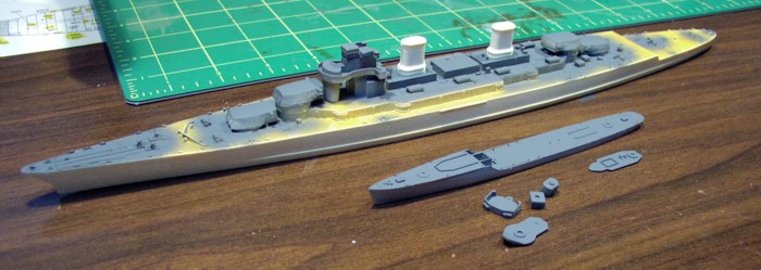
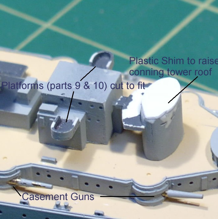
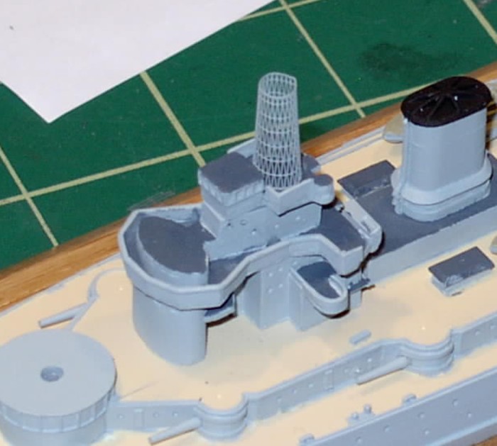
Upon test fitting the parts, I found Part C1, the top of the conning tower and navigation bridge, fit correctly onto part C2 - the superstructure - but then there was a gap between Part C1 and Part A3, the conning tower. I slid a few pieces of scrap plastic into the gap until I found the right thickness, then cut and glued a piece onto the top of Part A3. Once it was dry, I trimmed and sanded it to fit the oval conning tower and test fitted Part C1 again. This time the fit was perfect. However, I decided to leave the bridge off for now and work on some of the other details.
 |
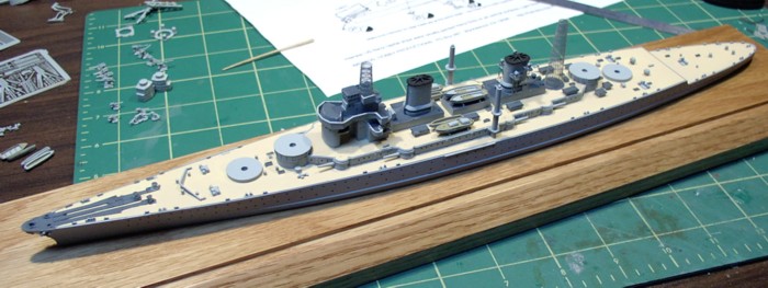
Painted with parts dry fitted |
 |
Since the casement guns were now in, I turned my attention to the 6 inch secondary guns and the 3 inch AA guns. The 6" guns look like knock-offs of Skywave's 5" guns. About half of the 8 white metal guns had bent barrels. These were easily fixed. The 3" guns were a different matter. Almost all of them (there are 6) were missing their barrels. I also thought they stood too tall. I dipped into the spare pool and found similar guns from Skywave. These guns looked more to scale and didn't sit nearly as high. All of these guns - both 6" and 3" - were assembled, painted and set aside to be added later in the build.
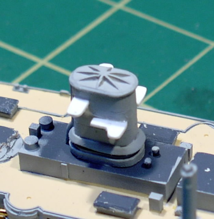
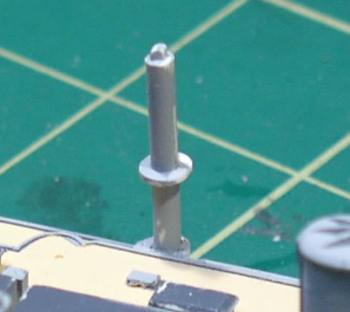
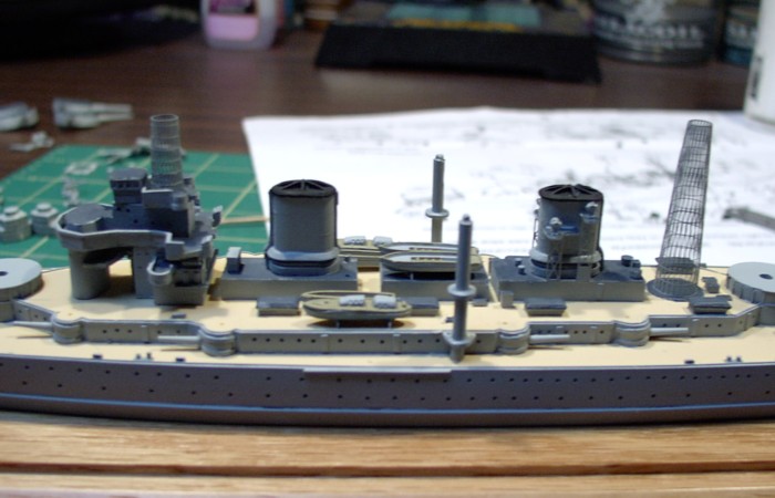
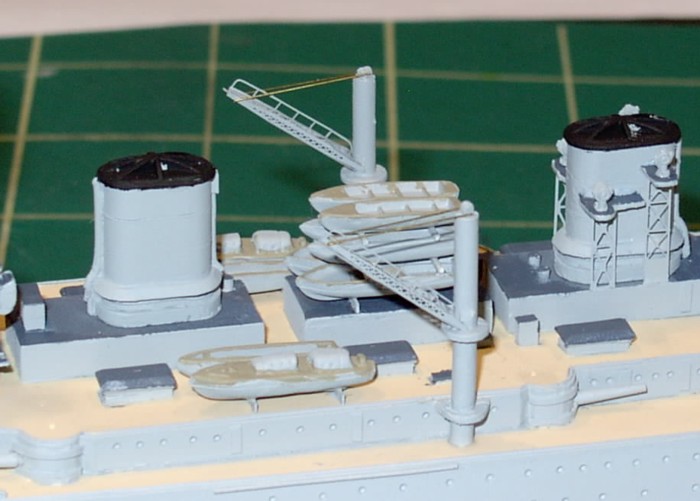
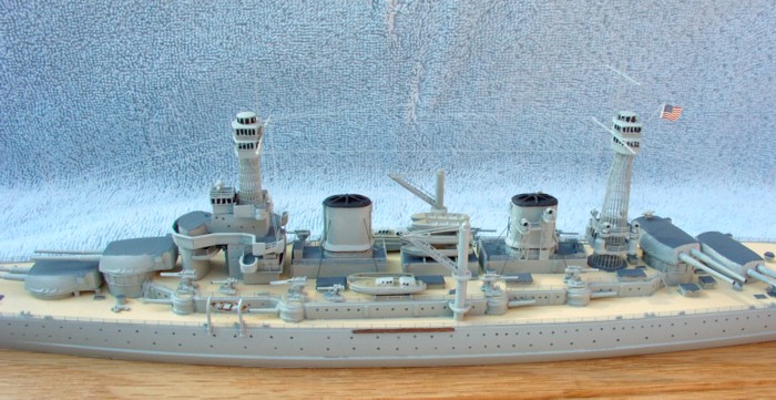
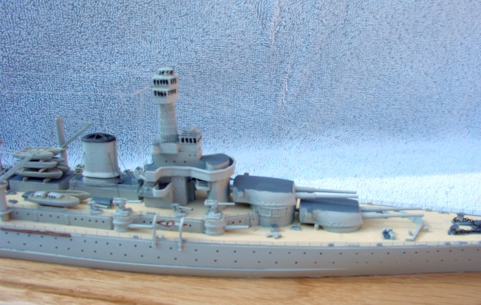
Next I added the funnels and then went to glue the platforms for the aft funnel into place. Both platforms (parts C6 & C7) were warped. I also thought they were a little over scale, so I made new ones from evergreen sheet plastic and glued them into place. I decided to replace the solid "lattice" support structures (parts C11 & C12) with pieces of photo-etch from an old GMM Japanese carrier set - but not until later.
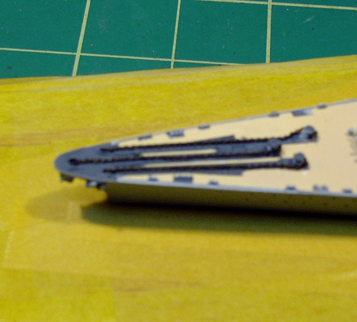
Once the platforms were dry, I added the posts for the boat cranes (A5) to either side of the hull. These massive posts look a little odd here - but the instructions and drawings/profiles from Beyer and Gibbons both match. They also match the boat cranes found on the Big 5 battlewagons. The crane posts were warped - I straightened them before mounting them, but noticed they had a tendency to bend after time. This part may have been better served being white metal and not resin. Since the resin "cranes" (part A7) were solid and too heavy looking, I left them off and elected to add photo-etch cranes from the Tom's ModelWorks #720 Early US Battleship set (which I originally bought just to have extra cage masts). The photo-etch cranes were left aside to be assembled and added later.
I moved back to the superstructure, concentrating on parts C9 and C10, which were platforms on either side of said superstructure. The instructions seem to show the platforms being added at the very front of the superstructure, while the included drawing from Beyer shows them further back. I elected to go with the drawing. Once I test fitted them, I found the two platforms protruded out too far for my taste, so I cut them down and glued them to the side of the superstructure. I then added some splinter shielding to make the superstructure look uniform with the platform.
The new platforms on the aft funnel |
The boat crane before adding photo-etched cranes |
Bridge assembly |
At this time, before going any further, I mounted the model onto the base I had ordered from Micro Mark. Using a small trowel like took, I spread some acrylic gel on the bottom of the hull, which was placed and then clamped onto the base and left to dry overnight.
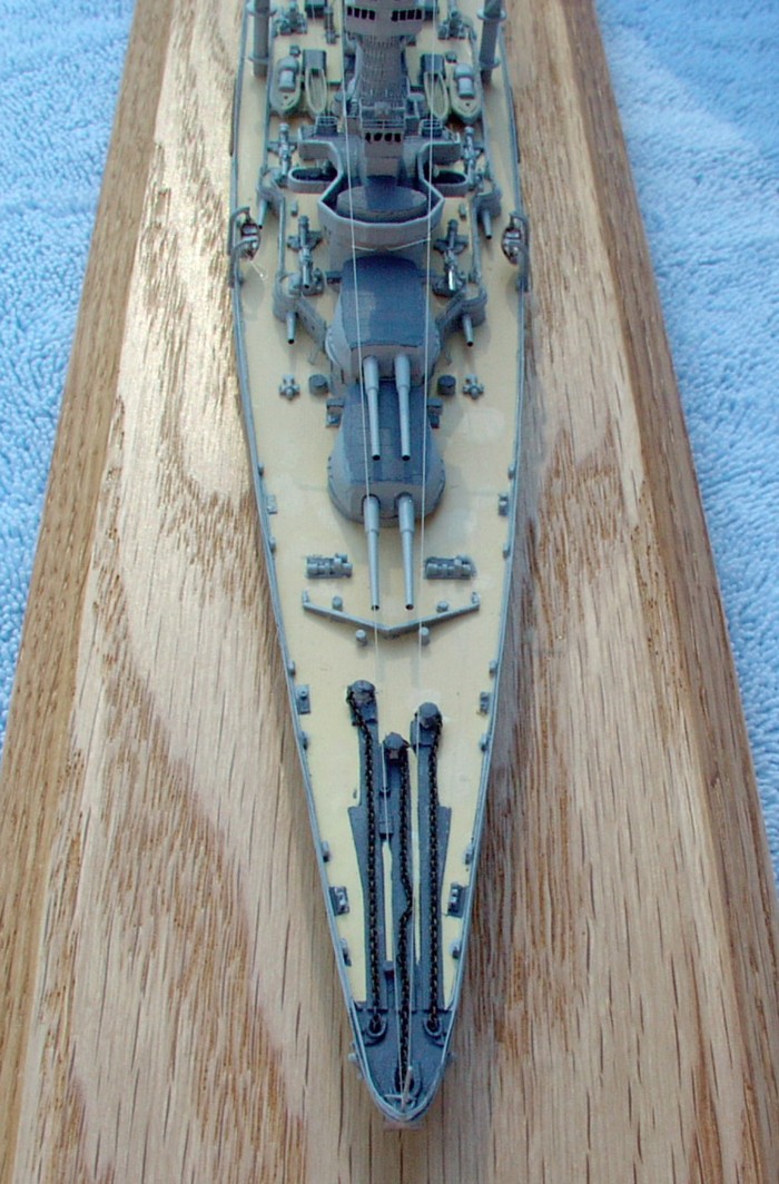
I now turned my attention to the ships boats - which I wanted to build and install before I put the photo-etch cranes and finished the cage masts. Knowing my tendency to be ham-handed, I figured it was better to get these on now before I started knocking parts off later. Since there were no boat cradles, I made some from strip styrene, cutting notches into them for the boats to sit. I made three pairs and installed them, using the line drawing and instructions as a guide. They were then painted and the boats mounted. For the center section of boats, I had to make two more sets of cradles, since these boats were stacked on top of each other. These had to be painted before being installed. So, while the paint on the cradles for the boats were drying, I started making my cage masts.
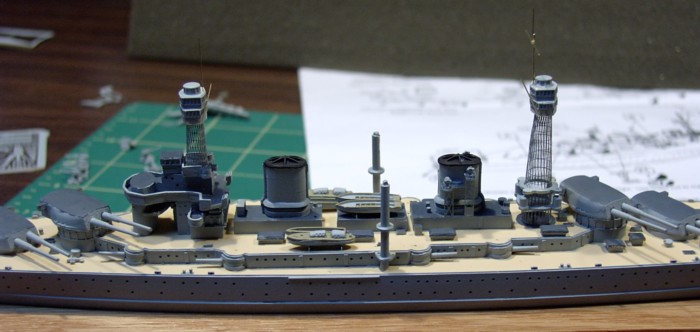
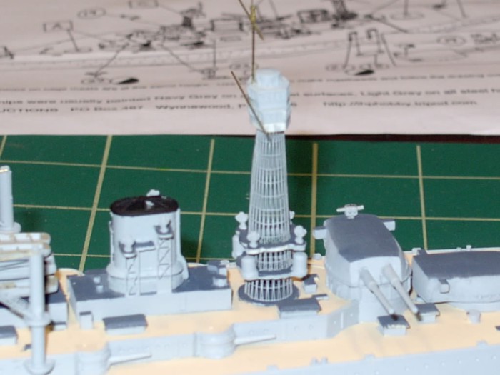
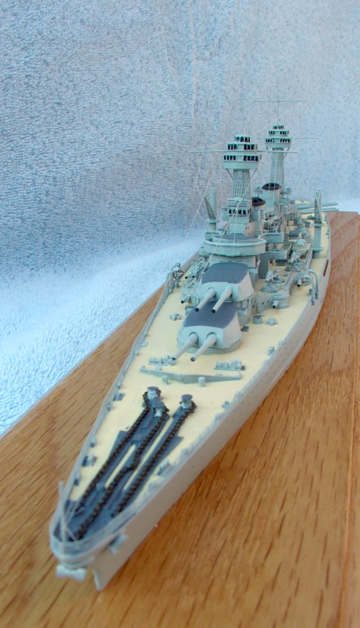
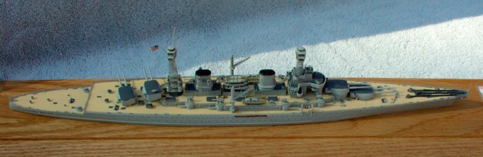
I have to admit I was a little timid about tackling the cage masts. I knew I had some leeway, because the photo-etch set I bought to supplement the kit had extra cage mast in it. Still...I knew I could go through both sets easily. I cut the foremast off it's runner, took out a large paintbrush and started rolling. To my surprise, it wasn't as hard as I thought it would be. I kept rolling the paintbrush gently over the photo-etch cage mast, gently bending the mast more and more. Before I knew it, I had an almost perfectly round mast. The trickiest part was mating up the two halves of the cage mast. I first brushed on some accelerator, let that dry, then held the tops of the cage mast together in my fingers. A drop of CA glue kept the top together, so I worked my down, mating the seam and adding CA. Once I was done, I placed it on the top of the forward superstructure and admired my handiwork. My first cage mast! I did the same thing for the mainmast, but accidentally glued the top of the mast to the paint brush handle (rrrrr!). I was able to gently pry the cage mast off the paint brush without too much damage.
 |
 |
 |
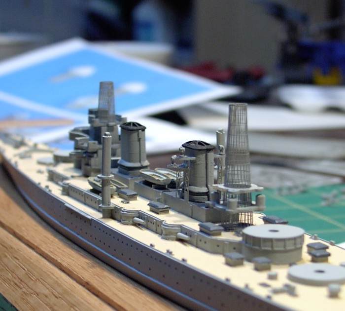 |
With the cage masts attached, I test fit the fighting tops. These are probably the roughest cast parts of the model, with rough casting inside the molded on "windows". The bottoms come with a protrusion that is supposed to fit inside the cage mast to help alignment. However, since the typical cage-masted ship in the USN didn't have this protrusion, I cut them off and sanded the bottoms of the fighting tops flat. One thing that surprised me when I first started working with resin was how fast you can sand it - so go slowly if you sand the fighting tops, lest you sand off too much!
 |
 |
The ships boats and completed boat cranes. |
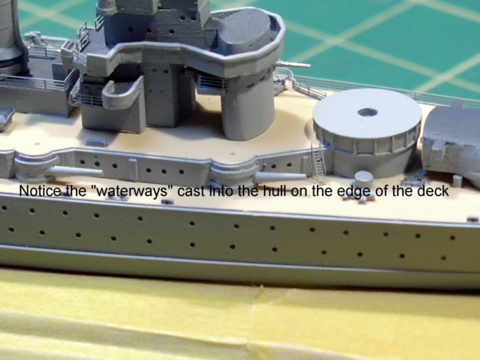
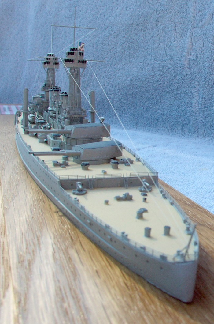
Once the paint dried, I started adding the photo-etched railings. Using some old Accurate Image railings for the USS Salem that my buddy Jeff had given me, I started with the forward superstructure and started working my way backwards. The railing of the midships superstructure areas was especially tedious. With the midships area done, began railing the boat deck level. If you build this model, you'll notice there is a raised waterway molded into the side of the deck on the main, quarter and boat deck levels. This helps facilitate the installation of the railings - assuming the you actually notice it.
 |
 |
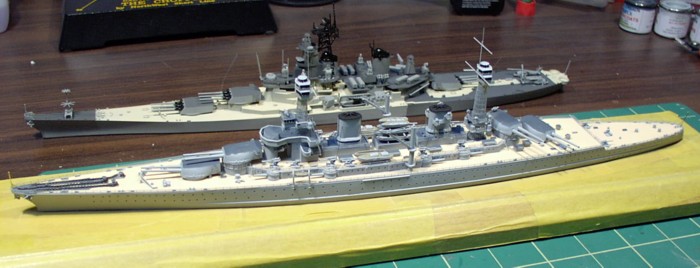
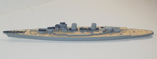
Garden State Firepower Lexington-class battlecruiser Saratoga alongside the Tamiya New Jersey - note how similar they are in size, but not design |
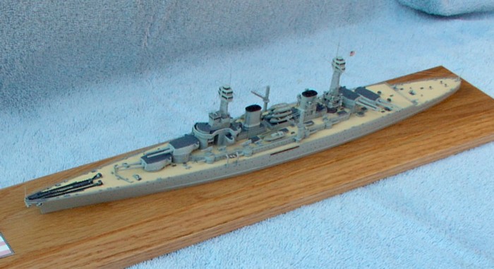
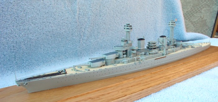
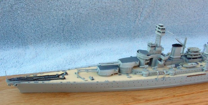
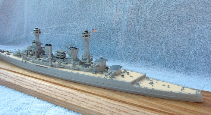
The model is marketed as, and is supposed to represent, the USS Lexington (CC-1), which would have been a fleet flagship. I couldn't find any references that indicated any differences between flagships and non-flagships, so I opted to "christen" my completed Lexington-class kit as the Battle Cruiser USS Saratoga, (CC-3). Saratoga was built at the now defunct New York Shipbuilding Corporation, located in the city of Camden in my home state of New Jersey. (The remains of the shipyard are located just south of the current site of the Battleship New Jersey Museum).
| Conclusion: |
|
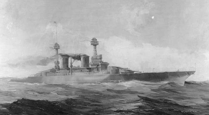
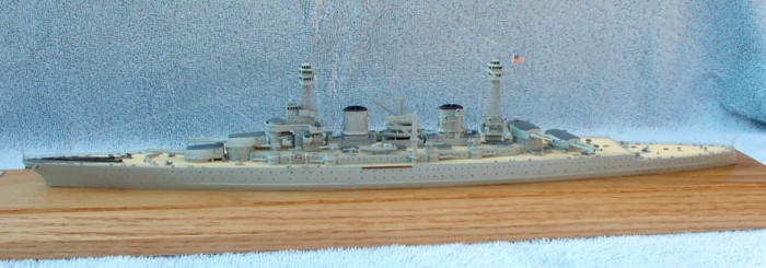
| The IHP Lexington presents
an intriguing "what-if". This kit gives the modeler a glimpse
of what the US Navy might have looked like if the Washington Naval Treaty
had not come to pass. The Lexington's - while flawed
- were majestic, powerful looking vessels.
Overall, the hull is well cast, but some of the smaller resin parts are a bit rough. IHP should have cast some resin parts (like the crane posts) in white metal, and done a little better quality control on the AA guns. Additionally, for the cost of the kit (approx $175 USD), I feel there should have been a complete set of photo-etching included, not just the cage masts. Finally, the directions are a little lacking. In the future, I'd like to see IHP include a separate page with a plan and profile of the ship for reference. Regardless of these shortcomings, I was pleased with the model and enjoyed building it very much. I heartily recommend it to anyone with a few resin kits under their belt who wants to round out their 1/700 battle fleet. Thanks to Imperial Hobby Productions for the review sample. |
|
 |
 |
 |
|
 |
 |
 |
|
 |
 |
 |
|
 |
 |
 |
|
 |
 |
||
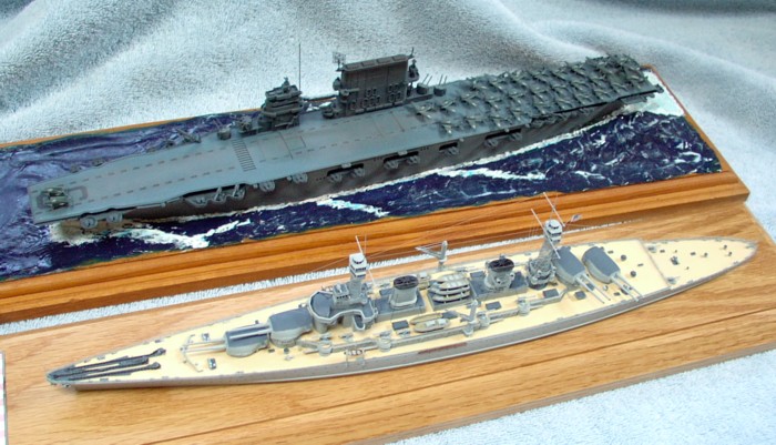
A Tale of Two Saratoga's As designed (1920) and as completed (1944) |
|||
