Scratch-building the Heavy Cruiser
USS San Francisco (CA-38)
Depicted as in January, 1936
Scale 1:192  (1/16” to the foot)
Model and Text by Gary Kingzett
Photos by Gary Kingzett, Brendan Quinn and Martin Quinn
 
 
The Ship
USS San Francisco was a heavy cruiser of the New Orleans class.   San Francisco was built at the Mare Island Naval Ship Yard in Vallejo, CA.  She was laid down  Sept 9, 1931, launched Mar. 9, 1933 and commissioned Feb. 10, 1934, Capt. Royal E. Ingersoll as her first commanding officer.
 
Length overall 588 feet
Beam  61 feet 9 inches
Draft  23 feet 
Displacement  9, 950 tons
Power plant
8 boilers driving 4 Westinghouse turbines, giving 107, 000 horsepower and a top speed of 32. 75 knots
Armament  9 - 8”/55 cal    main battery
8 - 5”/25 cal    antiaircraft 
8 - 0.50 cal       machine guns
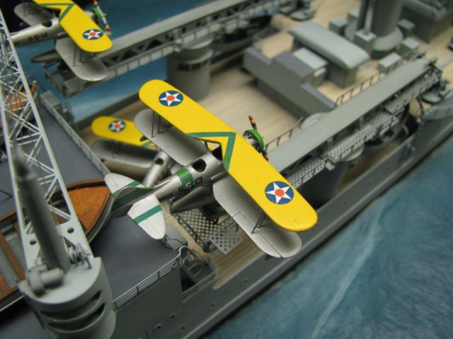
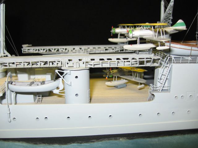
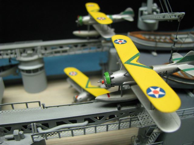
Aircraft  4 - Vought O3U-3 Corsair float planes
Complement  101 officers   803 enlisted men
 
Brief History
San Francisco received 17 Battle Stars, and one Presidential Unit Citation for outstanding performance of duties during World War II.  She was the 2nd most decorated US ship of WW II.  Most notable for her efforts in the Solomon Islands and at Guadalcanal in October and November, 1942,  she and a few other US cruisers and destroyers confronted Japanese battleships and cruisers,  when we had no larger vessels available.  218 men died in combat aboard San Francisco during WW II.  She fought all during the war, was decommissioned in 1946, and was sold and scrapped in 1959.  The navigating  bridge, on which the admiral commanding the US force at the Naval Battle of Guadalcanal, Adm. Daniel Callaghan, and her Captain, Cassin Young, were killed, has been saved as a Memorial to the ship and her men.  The Memorial is at Land’s End in San Francisco.   It looks out over the Pacific, along the great circle route across the water toward her old wartime adversary, Japan.
 
The Model
The ship is depicted in a fairly calm sea,  sailing at about 20 knots.  The overall gray paint is Standard Navy Gray # 5, which was a peacetime color.  Metal decks are Deck Gray # 20, with all wooden decks depicting holystoned teak.  The 4 aircraft are Vought O3U-3’s,  which she carried until April, 1936.   The boats are 2 - 50’ motor launches and 2 - 26’ motor whale boats.
 
The green stripes on the forward turrets designate the flagship of Cruiser Division 7.  The yellow upper surface of the #3 turret is specific for the San Francisco, and the green stripes on the aircraft represent the ship’s assignment as flagship of that division.  However, these recognition colors and patterns are the subject of much contradictory information.  Various published sources indicate that San Francisco was either in CruDiv 6, or 8, or 7, and her position in those various divisions is unclear.  I have a copy of the San Francisco’s Cruise book, written and published by her own crew.  it states unequivocally that she was flagship of Division 7 from 1935-1940, so I selected that.  Apparently, no one knows for sure about the recognition color on the aft turret.  I interviewed a member of San Francisco’s air crew.  His shipmates all say he has a fantastic memory.  He says that the San Francisco’s #3 turret top was painted all over Chrome yellow, to match the color of the aircraft wings, and that her number was painted on it, as shown here.  He should know, it was his job to use that color and number to spot his ship and get himself, his plane and his pilot back to the ship safely.  In absence of harder data, and as a tribute to a man who was there,  that is the paint scheme I chose.
 
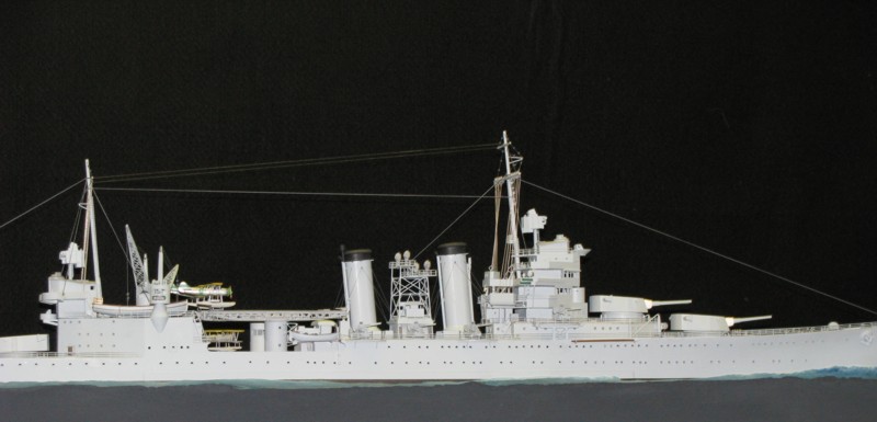
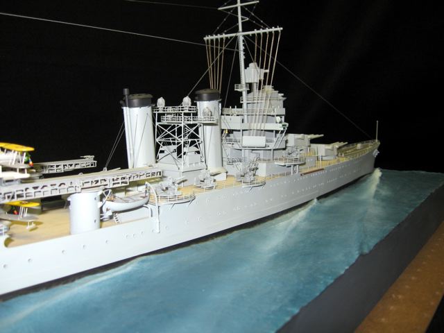
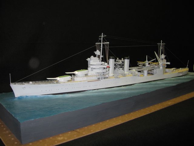
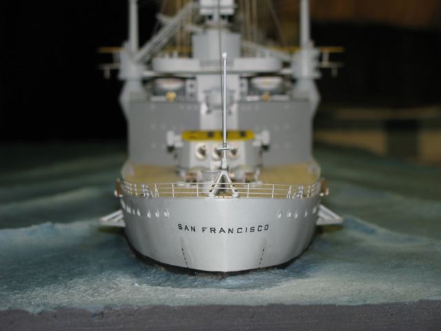
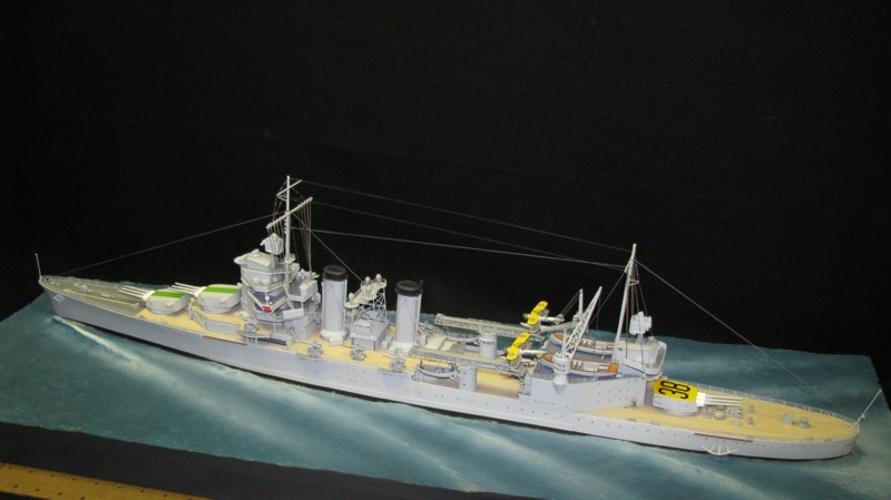
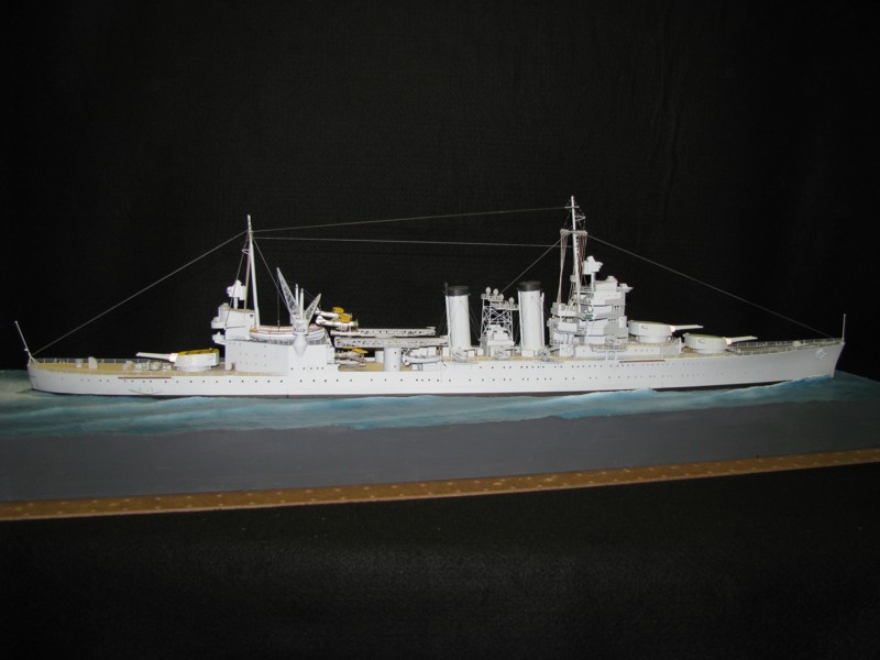
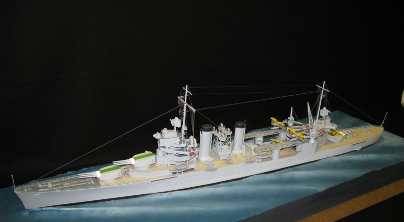
The water is SculptaMold,  a paper mache which I mixed with carpenter's white glue and applied with a teaspoon and other instruments.  The white glue makes it tough,  and it can be painted with both brush and airbrush.  The SculptaMold was applied around a ship shaped piece of 1/4" Masonite, which was removed after the material dried, leaving a perfect depression in which to mount the ship. USS San Francisco, sailing about 20 knots in a fairly calm sea.  The model is 1:192, mostly scratchbuilt,  with purchased photo etch from Tom's  Model Works and Blue Jacket Shipcrafters. The photos were taken under fluorescent lights, which gave a yellow cast to some of the pictures.  Hopefully it looks a little like bright sunlight.
 
References
Plans 
  • Tom Walkowiak, Floating Drydock, Kresgeville, PA,  drawn 1962
  • US Navy Bureau of Construction and Repair Booklet of General Plans, original undated, alterations corrected to October 10, 1944
Books and publications
    US Cruisers,  A Design History,  Norman Friedman  US Naval Institute Press,  1984
    US Naval Weapons ibid. 1985
    Warship Pictorial  #5, San Francisco,   Classic Warships Publishing 
    Warship Pictorial # 2  Minneapolis  ibid.
    Warship Pictorial # 7  New Orleans Class ibid.
    Warship Pictorial #14 Wichita ibid.
    Profile Morski  USS San Francisco, BS Firma Wydawniczo Handlowa 1995 
    US Heavy Cruisers in Action  Squadron/Signal Publications  2001
    Model Ship Builder,  periodical, article in 3 consecutive bimonthly issues, 1982  Building USS San Francisco, by Ray Crean
    Battleship & Cruiser Aircraft of the US Navy, 1910 - 1949 William T. Larkins   Schiffer Publishing 1996
    Battleship Country The Battlefleet at San Pedro/Long Beach 1910-1940 Harvey M. Biegel ,  Pictorial Histories Publishing   1983
    Cruisers   Anthony Preston
    Cruisers of World War II  M.J. Whitley
    USS San Francisco,  One Ship    The Crew’s Cruise Book  circa 1946
    USS San Francisco, A Technical History,  Hansen Publishing Chuck Hansen  1981
Internet sources 
(Google searches for websites and photos)
    Dictionary of American Fighting Ships 
    Naval Historical Center
    NavSource
    San Francisco Memorial Foundation
    ModelWarship.com
    Steel Navy.com
    American Aviation Historical Society
    Vought Aircraft. com
    Aviation Enthusiast’s Corner
Individual sources -  from personal Interviews and conversations
    Art McArdle  San Francisco crew member 1936 - 1940
    Dana Bell  a retired Smithsonian curator, expert on ship and aircraft painting and markings
    Art Herrick  retired professional model maker and naval researcher
    Fritz Koopman  naval propulsion engineer and naval history enthusiast
    Al Ross  author, designer and model maker for Bluejacket Shipcrafters
    Charles Landrum  retired Navy Commander and naval historian
    Don Pruel, master model maker annd now curator of the ship model collection at the Naval Academy, Annapolis
    Dick Jansen  amateur naval historian and collector
    Steve Wiper  researcher and publisher of  Warship Pictorials 
    Ray Juncal  professional model builder and researcher of Navy subjects
    A.D. Baker III  historian and draftsman,  responsible for most of the drawings found in published information on naval ships
    Jack Wallace, retired Navy commander, commercial pilot and the son of John Wallace, recipient of the Navy Cross for his heroism when the San Francisco was hit by a crashing Betty Nov 12, 1942
    Darren Scannell, naval historian, producer of ship models and decals
    Steve Nuttall  machinist and producer of miniature brass gun barrels.  Steve produced 10 beautiful guns for San Francisco, using my and his dimensions
    Louis Parker,  San Francisco crewman, 1944 - 1945,  naval historian and photo archivist, acknowledged source of many of the photos published in the references cited here and many more.
 
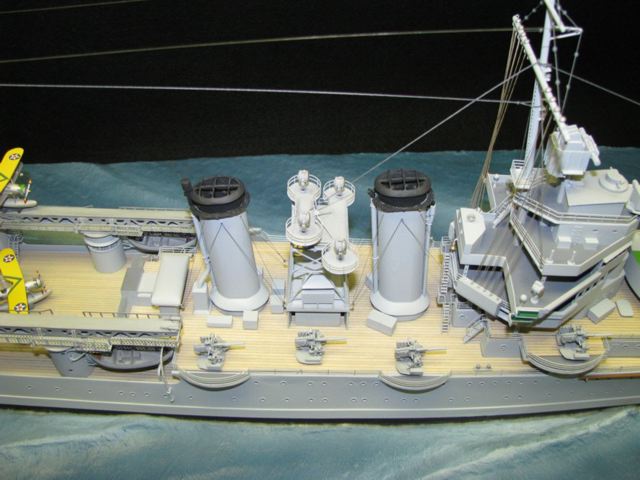
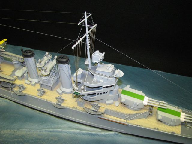
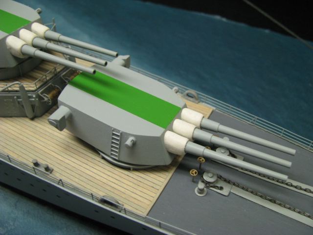
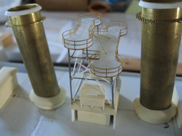
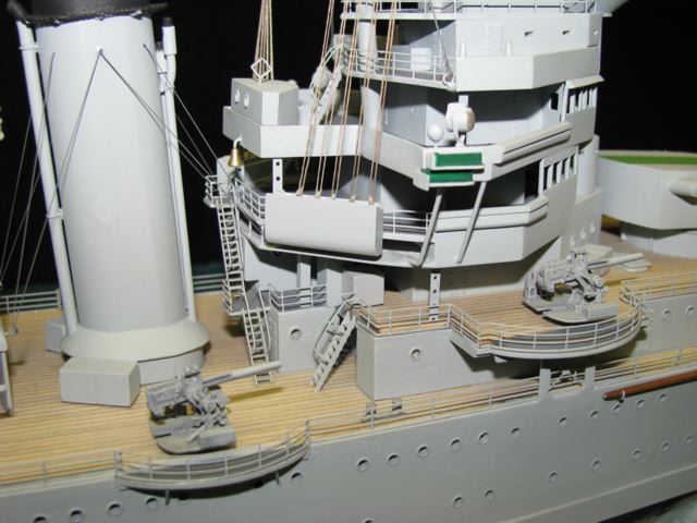
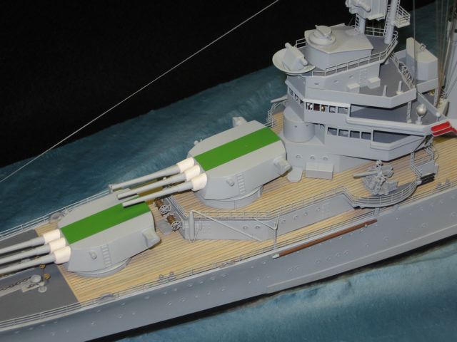
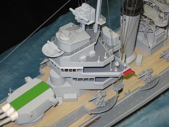
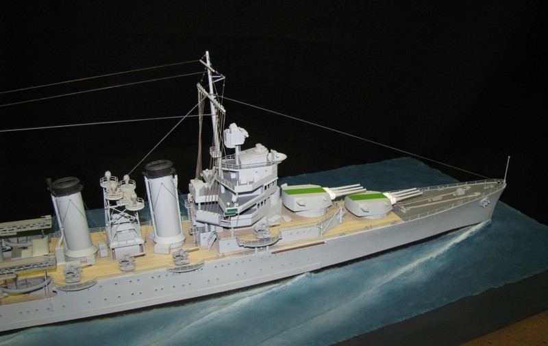
The wood deck is actually pre glued basswood sheet from Northeast Products.  I toned down the basswood color with a coat of Dune Gray wiping stain, most of which was wiped off, leaving a hint of gray which matched the color scheme very well. The green stripes denote the flagship of CruDiv 7.  I picked that color, to conform to the Willow Green stripes on the aircraft. View of the funnel and searchlight platform.
 
Materials for Constructing the Model
The hull of the model is constructed from .060” polystyrene,  using a central profile board (spine),  an .080 styrene plate at the water line, and bulkhead formers at every hull station.  The hull was plated using .030 styrene sheet, with cast blocks of ButterBoard, a cast urethane material cemented to the bow and stern, then carved and faired to shape.   All the plastic joints are welded using solvent cement.  Joining of dissimilar materials, such as the butter board and the wood to the styrene uses 2 part epoxy.  Any joints subject to physical strain are pinned as well as glued.
 
As built, the San Francisco had many portholes. They are a very distinctive part of her appearance.  I made each one by drilling a suitable size hole, then sliding in a short piece of plastic tubing, gluing it and leaving it protrude just a bit.  I then used a small tapered reamer, to enlarge the portholes to the correct size, which thinned the tube to just the right thickness as a rim.  I didn’t put glass in each porthole,  I liked the visual contrast between the hull and the portholes.
 
The main sub-deck is styrene, with pre-glued basswood planking installed on all weather decks. Fully enclosed upper structures are ButterBoard, exposed decks and open structures are fabricated from styrene sheet.  The turrets are ButterBoard, cut and sanded to shape,  the gun barrels are mounted behind a faceplate, so they protrude through the turret face, but the barrels are fitted with fabricated blast bags to cover the joint.
 
The aircraft cranes,  housings and supports are fabricated from brass and plastic;  The crane jibs and the catapults are photo etch from Tom’s Modelworks, folded and strengthened before mounting.
 
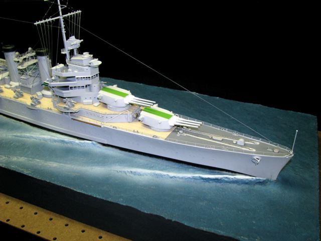
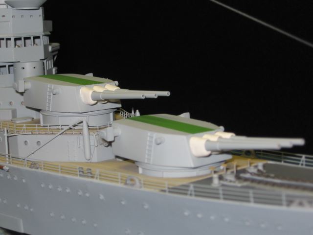
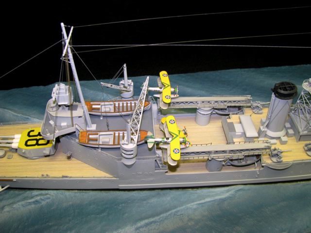
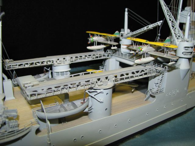
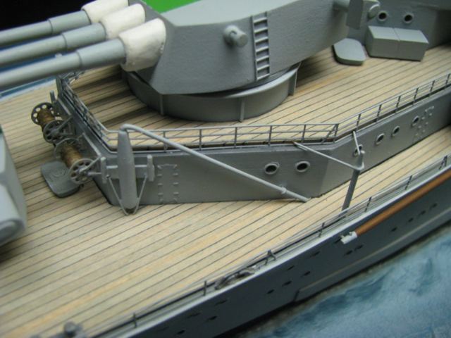
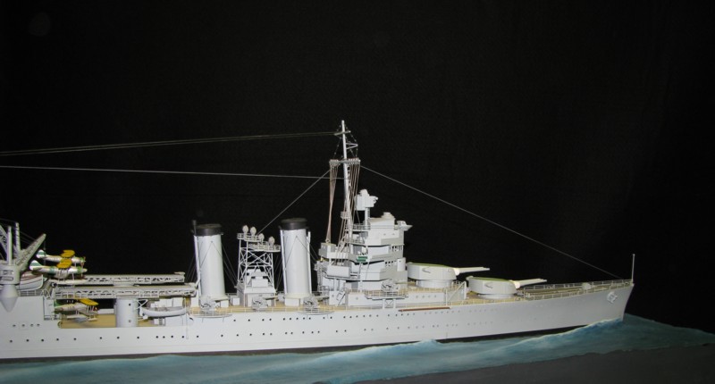
The catapults, aircraft and ships boats I put in all the detail I could for 1936,  but it  is apparent that there was a lot of deck space for the installation of 20 and 40 mm anti aircraft guns when war broke out. A very nice angle where you can see the lean contour of the ship.
 
The 50’ launches are vacuum formed styrene, with decks, fittings, strakes, rudders and props cemented on.  The whale boats are cast pieces purchased from Bluejacket, with extra details added.
 
The 5”-  25/cal  weapons are castings from Don Pruel at J & D Productions.  Each of the 8 assemblies consists of 13 separate cast parts, which I assembled, then added some extra detail and installed.  I fabricated the Mk 3 mountings for the 50 caliber machine guns, but I left those guns unmounted, assuming they would be stored in peacetime.
 
Deck machinery and fittings are a combination of cast Bluejacket parts, chocks, bollards etc.,  and fabricated fans, controls, hydrants, etc.
 
Masts and spars are fabricated and formed from brass tube and rod,  tapered and shaped, then soldered together for strength.  The recognition lights are tiny glass beads.
 
The 4 aircraft are scratch built from ButterBoard for the fuselage and floats,  and styrene and wire for the wings.  Each of the rotary engines has individual cylinders in proper location,  covered by the cowl.   The propellers are fabricated from styrene.  The plane dollies were fabricated of brass and plastic.  Art McArdle told me how the planes were spotted.  The section leader’s plane is up on the starboard catapult, his wing man is on the port catapult, No. 3 is in the well deck, with No. 4 behind it.
 
Up in the pilot house on the navigation bridge, the binnacle, ship’s wheel, engine telegraphs and repeaters, voice tubes and chart tables were fabricated, painted and installed.

 
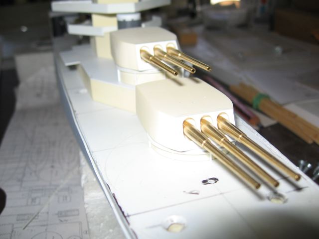
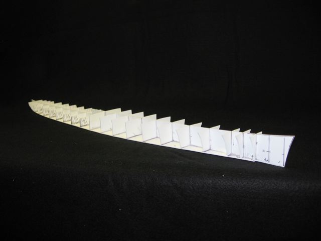
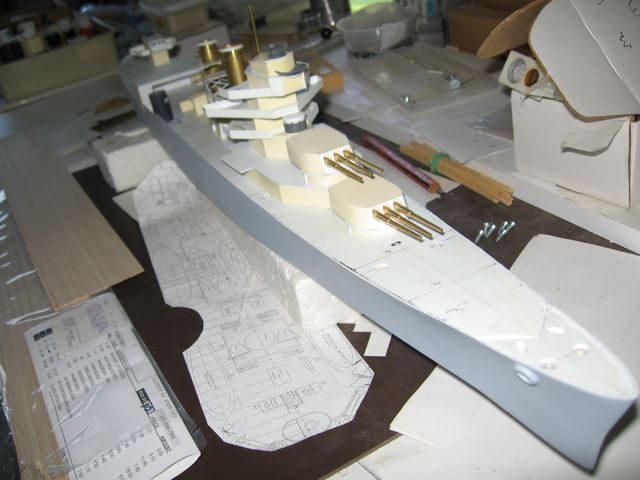
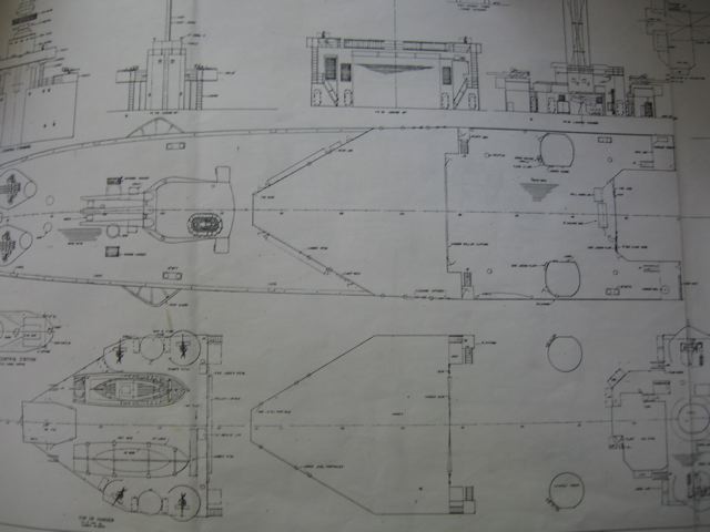
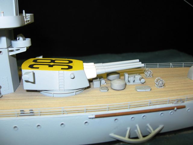
The hull is fabricated from a waterline plate, inboard profile,  and bulkheads at every hull station.  The Floating Drydock drawings show all these shapes, it is a simple matter to lay them out, cut them and make them into an eggcrate. The hull was plated with a sheet of polystyrene on each side.  The bow and stern are carved from solid blocks of butterboard, glued and faired into place.  The main deck was left loose until late in the construction. Steve Nuttall supplied the barrels.  He had the overall dimensions, and I supplied the dimensions of the muzzle.  I got those from several superb photos in the original San Francisco Crew's book which I have.
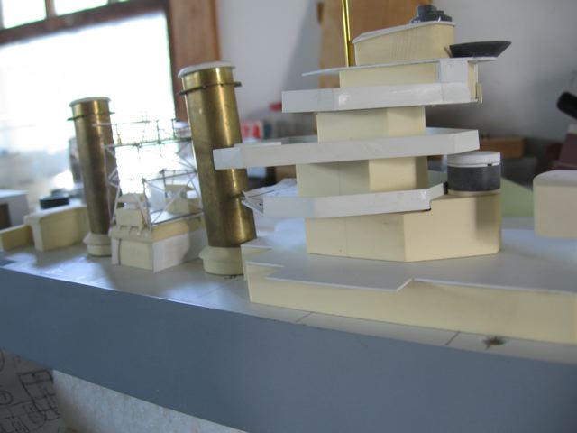
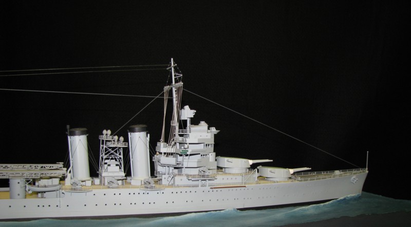
The stacks were made from flattened brass tube.  The searchlight tower is supported on steel wire, hard to form and cut, but very strong. The Floating Drydock plans were originally 1:96, I had them photographically reduced to 1:192.  Perhaps you can see the detail of the front of the hanger.  The drawings depict the 1944 fit. I didn't have plans for the superstructure for the date of my model.  I scaled a lot of photographs to develop the size and shape, but ultimately, I spent much time doing temporary fit ups to make sure there was room for everything.

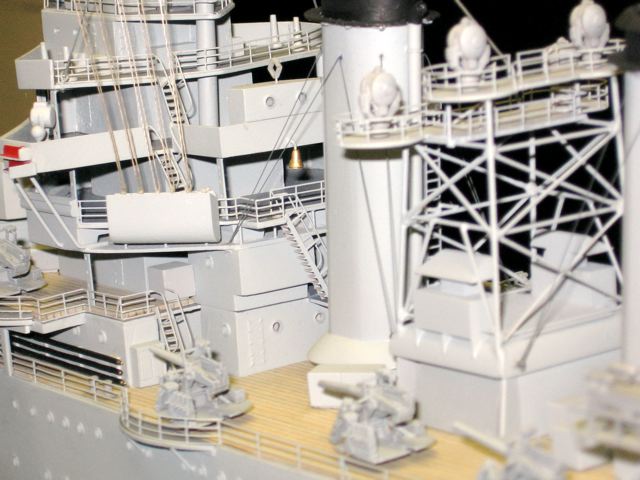
The main and secondary gun directors were fabricated and installed.  I looked fruitlessly for months trying to find what the directors actually looked like from above.  None of my sources could help me.  Finally I happened across a picture of Astoria being refit, which was taken looking down into the director.  That information, combined with the Friedman book on weapons allowed me to construct the directors accurately.

 
All the inclined ladders, stanchions and railings are photo etch from Bluejacket.  It was a generic sheet in the proper scale;  I was able to cut and fit all the necessary pieces.  I am a nut about railings.  As best I could, I mounted the railings down in the waterway where the lowest railing would not be seen.  And doing it this way, I have a natural guide, so the rails don’t wander. (Too badly)  Notice that the upper rails connect at each change of direction.  A tiny crew man would not fall.  The treads of the inclined ladders are properly oriented, so that same crew man could climb up and down.
 
Various staffs, booms, paravanes, pipes and hoses were fabricated and installed.  Where necessary, they were tapered to scale size or slightly smaller for enhanced appearance.
 
Photo etch ladders were installed on the sides of the turrets and up the masts.  Navigation lights were fabricated from plastic sheet and glass beads.
 
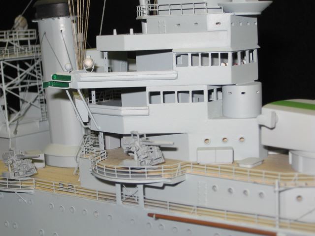
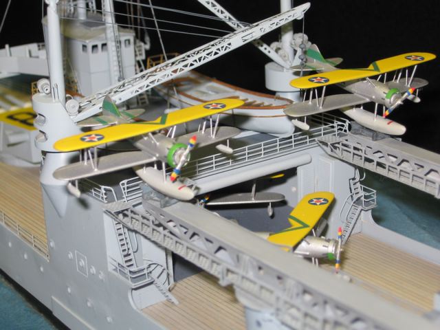
It is hard to see, but the various bridges are furnished with appropriate equipment and instruments.  I didn't glaze the windows so it would be possible  to see in. I could not find any pictures of the rear of the fore superstructure for my time period.  I worked backward from the 1942 Mare Island photos to find where the inclined ladders and other details had to be. There  are 4 - Vought O3U-3 Corsairs aboard.  The Corsairs were replaced by SOC's in April of 1936, hence my model date of January '36.  An air crewman who was aboard in 1936 told me how the planes were arranged and stowed.  The aft end of the hanger housed crew washrooms.  At this scale it is impossible to see into the hanger,  I doubt it would be a problem in 1:350 or 700.
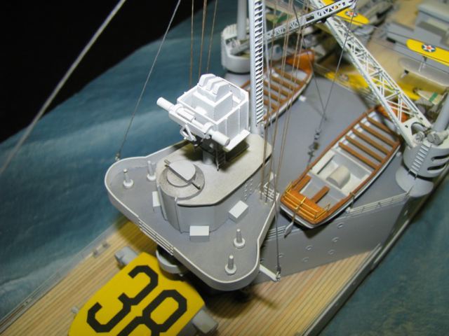
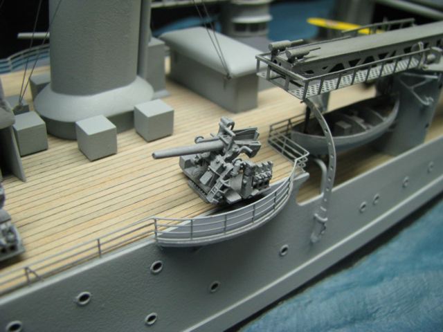
Stowage of the 26' motor whaleboats didn't seem to change during the ship's lifetime.  The bow of the boat rested on a beam and was suspended from a formed davit.  The after end rested on a pad on a pivoting bracket.  The after tackle was suspended from a pivoting crane.  To launch the boat,  the tackle would be tightened and the stern and the crane would be swung out.  This would pull the bow clear of the forward davit, which would then be pivoted aft, carrying the bow out over the water. Clearances everywhere were very tight.  I had to move the catapult housing forward 1/8" to clear the railings, cranes, and launches. The Mark 28 directors were open on top.  The 3 crewmen who aimed the director sat on an open bench behind the sighting scopes. Motive power to train and tilt the director was supplied by a man pedaling a bicycle crank, inside the director.  After much searching, I found a photo of Astoria taken from above which showed the interior details.
 
The ship was rigged using a combination of mono filament where a smooth small line was needed,  and various sizes of fishing line were used for the heavier lines.  The signal halyards were left natural to simulate hemp,  the standing rigging was dyed a faded black to simulate weathered tarred cable.  I did not install the standing rigging, fore and aft stays until after the ship was mounted.  I didn’t want to take a chance on the lines going slack, or getting too tight when the ship was mounted.
 
Early on, I constructed the base.  I prefer the base to look like a stone plinth.  This gives a clear line of demarcation between the real world, and the miniature world I am creating, but does not interfere with either of them.  After making the wood base, I also traced around the water line of the ship and cut that shape out of a piece of 1/4” Masonite sheet.  I screwed that piece down to the base in the final location of the ship.  I prefer the ship to be mounted at a slight angle, not straight with the center line.  This implies life and motion.  On the inside bottom of the base plate I attached a piece of angle aluminum as a reinforcement to keep the base flat.

 
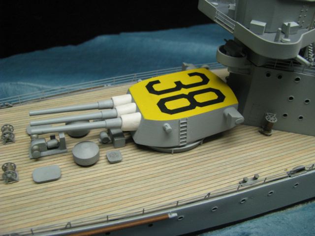
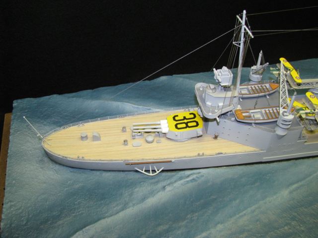
Art McArdle, an enlisted member of San Francisco's flight crew insists that the entire #3 turret top was painted chrome yellow for recognition.  Published data is unclear on that point.  Art was there, and it was important for  him to be able to spot his ship and get home.  I took his word for it.
 
I mixed  a paste of SculptaMold paper mache,  and white carpenter’s glue, then troweled this on to shape the waves.  I use any implements I can get my hands on, but by far the most useful is a plain old teaspoon.  After I have the basic shape done, I let it dry a couple of days, then slather on another layer to fill in anywhere it needs it.  It is necessary to let the first coat harden so I have a firm surface to work with the second time.  After I am satisfied, I let the paper mache dry, which usually take a couple of weeks. I remove the false hull which I worked around, and I have a ship-shaped depression in which I can install the model when I am ready.
 
I brush on several coats of gel artists medium.  This seals the papier mache, fills in any low spots, and gives me a slightly windblown texture which adds some visual interest to the surface.  After that is dry, I brush on a coat of acrylic paint, which I have mixed up to give the very deepest blue color, which would only be seen down in the troughs.  The color is selected to complement the color of the  model itself.    Then I make a batch of white acrylic, into which I have mixed some of the base color giving a very light blue, airbrush it onto the surface, to accentuate the high spots, while leaving the troughs dark because the sun would not be lighting that area.
 
When building the hull, I had installed threaded nuts securely within, and before closing up the hull, I marked and drilled locations for matching holes to install mounting screws.  When I am ready to install the ship, it is merely a matter of placing it in the depression, and running machine screws up through the base into the hull.  My hull was slightly warped (banana shaped) but the screws pulled it down nicely.
 
I try to paint as I go.  I dislike masking, so I tend to build substructures  which have natural joints where they would be on the real ship.  Then I can paint a piece all one color, and don’t have to mask, and I don’t have to do much touch up after the piece is installed.  Of course, I still have to do some masking, and touch up, but not much.  I cut out the wood deck to finished size, then painted around where it would go, then traced and cut out for most of the superstructure pieces , off the model. Then I could glue the wood down with 2 ton epoxy (to make sure that the glue would be strong enough to keep the deck from moving or curling with changes in temperature and humidity).  When it was set, I glued the painted superstructure pieces into their holes.  they fit very well, without fuss.   Many of the deck fittings are too small to do that.  For them I prefabricate.  Before I paint them, I drill them and glue in a small piece of wire which I use as a locator pin.  I push the pins through a piece of cardboard to hold the pieces while I paint them, and I drill a hole through the deck where the piece ultimately has to go.  It is easier for me to locate a small hole, and I use slow drying glue for final assembly, so I know each piece is where I want it to be, and I can easily align it before the glue dries.

 
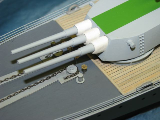
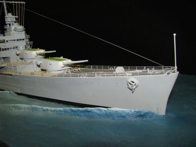
The brown flange is normally covered by the acrylic case and a finished frame,  which were removed for these photos. Another view of the green stripes, which denote San Francisco the flagship of CruDiv 7. I couldn't find any studded anchor chain of the correct size, 15 links to the inch, and I didn't want photo etched chain.  Th control wheels for the capstans are photo etch on steel pins.
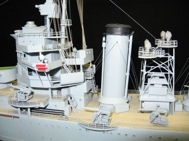
Cable reels,  paravanes,  boat booms and support spars at  the fore end of the superstructure.  All the portholes, superstructure and hull,  consist of a short piece of styrene tube glued into a drilled hole, then sanded to be ,010" proud of the bulkhead.  Then I used a tapered miniature reamer in each one to make the rim the correct thickness. I thought the 50 caliber machine gun pedestals were conical as shown here.  Later I found out the Mk 3 mount is an offset casting.  I have since installed Mk 3's.  I did leave the machine guns off.   I figured they would not have been mounted in peacetime, except during exercises. Bridge, funnel and searchlight platform details.  Note the ships bell.
 
I use automotive primer as my first coat for painting.  This allows me to sand any roughness if I need to.  The final coats of San Francisco are ModelMaster Acrylic,  Standard Navy Gray # 5, and Deck Gray # 20.  Many of the fittings and structures were toned down slightly with a  dilute mixture of varnish ahd black artist’s pigment.  This slight toning down adds some interest without calling attention to itself.  The boot topping around the bottom of the hull is in fact automotive striping tape,  a dark gray, not black.  The striping tape is permanent, goes on straight and doesn’t have any smears or overspray.
 
I believe in scale effect for painting.  I liked the Standard Gray # 5 as it came from the bottle, and Deck Gray is neutral so I didn’t worry about it, but the black at the top of the stacks is in fact 15% white and 85% black, and all the other colors and accents are toned down also.  This prevents garish contrasts.   The wood deck was toned down with a coat of Dune Gray wiping stain before it was cut and installed.  (Most of the stain was wiped off, but it did a great job of blending the wood tone into the overall palette.)
 
After the ship was in place, I brushed several coats of clear (actually translucent white) gel medium into the joint between the base and the ship.  This puts the ship INTO the water,  and allows me to fill any cracks or depressions which might show up.  The gel slops up onto the boot topping, just as sea water would.  It goes on white, so you can see what you are doing, but dries translucent and does a perfect job of subtly disguising the joint.

  
To my eye, the ship is very attractive from this angle.  Note the stowage of several lengths of refueling hose along the bulkhead under the forward 5". The 5" -25's came from J & D Productions.  Each one consists of 13 castings, plus I added some brackets, cranks and motors.  It was a challenge to make the rest of the model measure up to these little beauties.  Port catapult and boat details
Another view of the Vought O3U-3 Corsairs  Another look at chrome yellow  of turret #3, which was used for recognition. The decals are from the Resin Shipyard.  The draft marks are perfectly legible, each number about .015" high.
 
I dislike shiny spots, even shiny metals aren’t shiny at this scale, so as a final step I give everything an airbrushed coat of Testors DullCote, which removes all the shine, and hides the glue spots.
 
My stepson is in the display business, and he recommended a case fabricator to me, Capitol Plastics in Beltsville, MD.  Their clear covers are gorgeous, they custom make them for the Smithsonian, and I am very pleased with the result.  The case never fails to get attention.  I had a frame shop locally build the visible wood frame for me, I pinned it to the Acrylic cover, and ran screws up from the flange of plinth into the wood.  The model is securely covered, but the cover can be removed if desired for photos,  and cleaning if that is ever necessary.
 
I worked on this model for 3  1/2 years.  I am not fast, but this is a hobby.    I am reasonably productive considering the amount of research required.   I conservatively calculate that I applied about 600 hours per year,  (300 days at an average of 2 hours per day) for a total of about 2000 hours for the project.
 
Destination

I built the model as a “Thank You” gift for Lou Parker.   For him and his shipmates who fought in World War II, and for the kind of man Lou is today, knowledgeable and helpful and encouraging to anyone who asks for anything  Navy.  I am going to take the model to the State of Washington and present it to Lou at his home.  Ultimately, he plans to donate it to the Mare Island Navy Yard Museum.  Hopefully the people at the museum will be pleased that one of their most famous alumni (or at least a model of her and her spirit) have finally come home.
 
Gary Kingzett
 

© ModelWarships.com