USS North Carolina BB 55
by Ron Horabin, Cheshire England
|
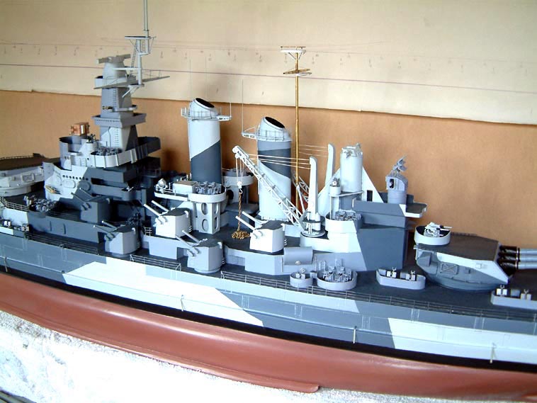
Part 9 Clipping Room, Air Inlets, Handrails, Flag Lockers, Boat Cranes. |
|||||||||
| On my visit to the ship I took some of my own photos which I am going to incorporate into this build section and some of the remaining updates, to help future model builders. | |||||||||
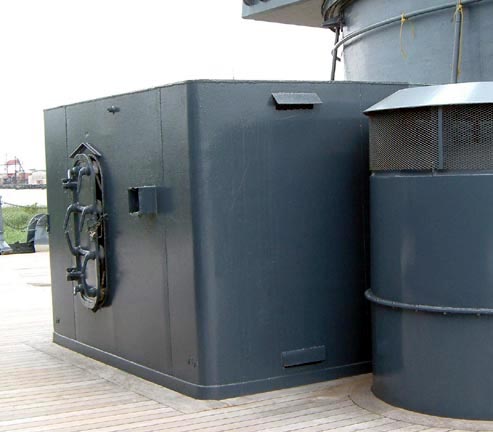
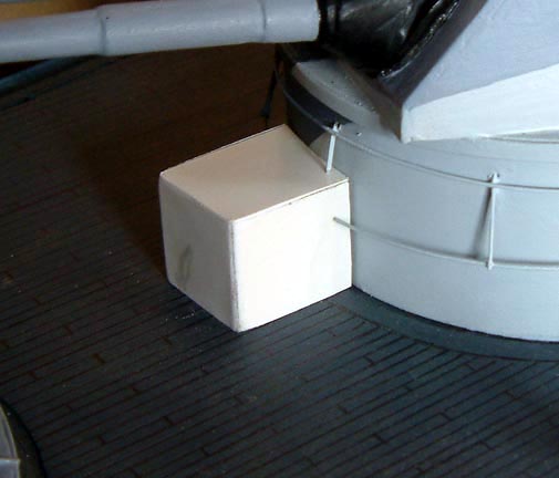
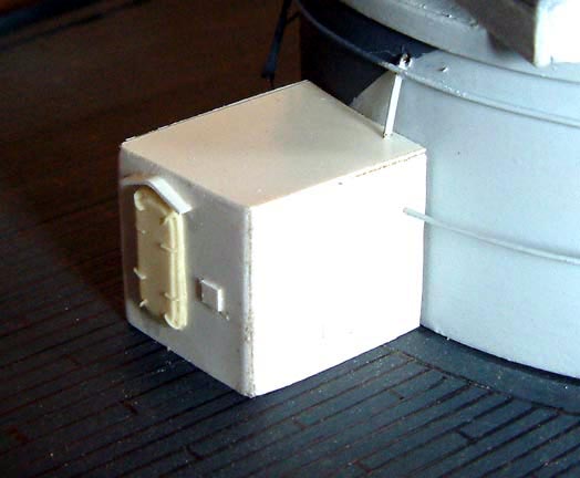
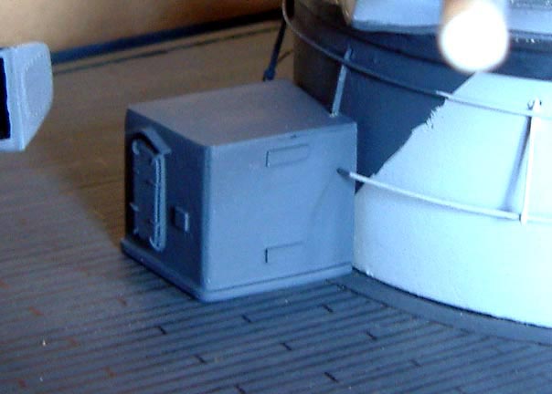
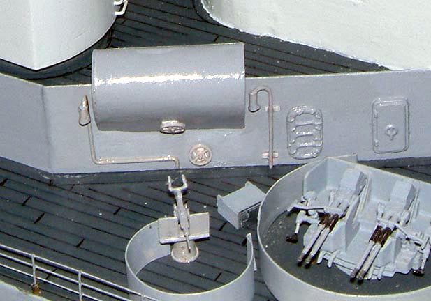
| Clipping room.
The main one was under the second 16 inch turret, using 40 thou thick plastic card or as some of you say Evergreen sheet, I cut three sides, a top and a base, gluing them together with liquid poly, I then added a door and some ventilation ducts, over the door was fitted a drain water, when every thing was dry it was given a coat of N5 blue, and fitted in place
|
|||||||||
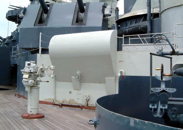
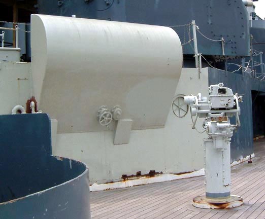
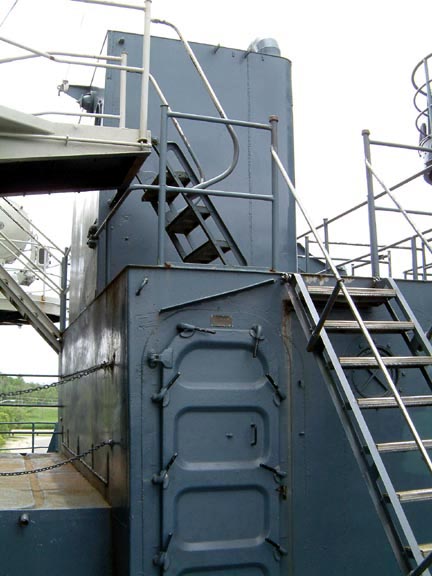
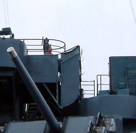
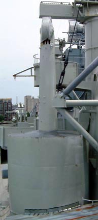
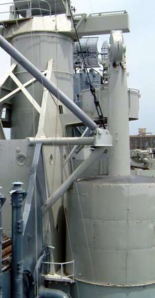
| Air vents.
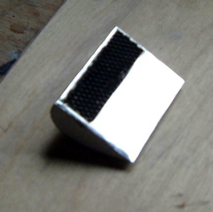
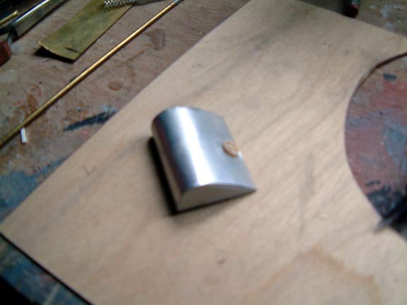
NC has two very large vents at the far end of her main superstructure, one on either side, I managed to get a photo of each one, making the vents was easy, using the plastic card and cutting the two ends to shape, and forming the back into a curve, the front was straight with a little metal grating attached to it. To the curved section I added a wheel, when fitted to the side of the superstructure I also added some vent pipes and another wheel under the vent and painted it grey, with the large grill , this was painted black.
|
|||||||||
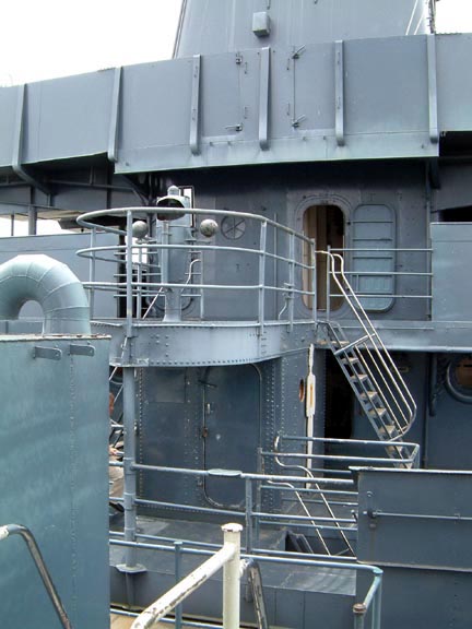
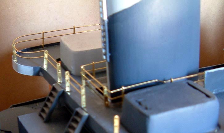
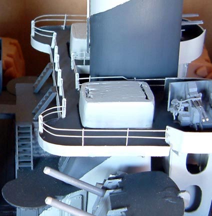
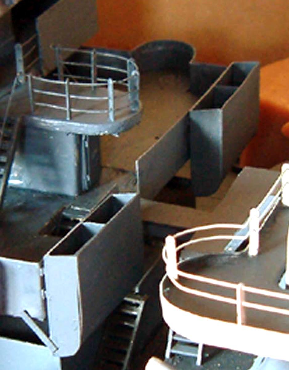
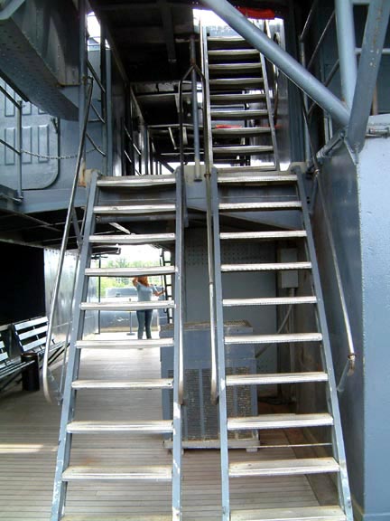
| Handrails & Stanchions.
The stanchions on the upper part of the superstructure are from the Billings model boat fittings collection, they come in small packets of 10, they are not cheep, they are solid brass drilled with three holes to accept brass rod, they are drilled in to the deck and super glued in place, the brass rod was passed through the stanchions and glued in place, when dry a coat of paint was applied, the colour depended on the colour of the back ground superstructure. |
 |
||||||||
|
|||||||||
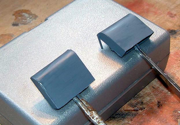
| Flag Lockers
There's two, one port and one starboard, they are positioned under the main yard arm on the flag and signal bridge, these again were cut from plastic card and glued, painted and fitted in place, when ready they will be filled with flags.
|
|||||||||
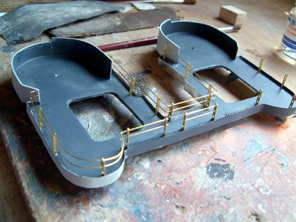
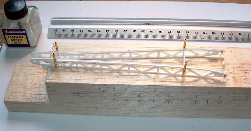
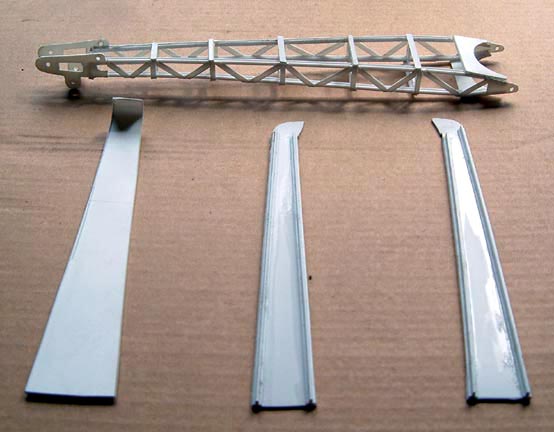
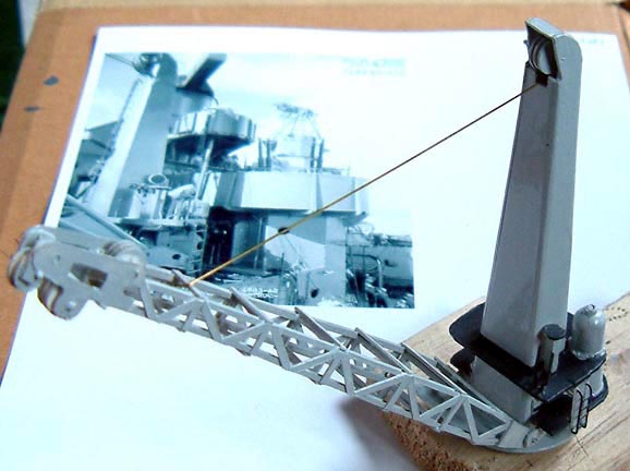
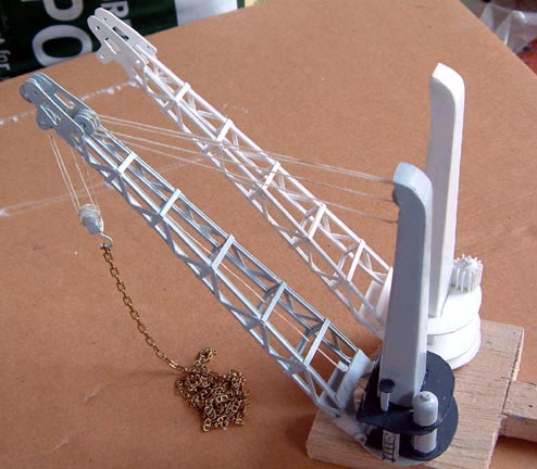
| Boat Cranes
On the drawings there is only a side on view of the cranes, very little information on how to build them, Brian and Tim both sent me the same photo, great photo but still not enough detailing of the bottom end working detail, searching though NC website I found a photo that gave me some idea on how to build the working platform. The first thing was to mark out the shape of the derrick and cut the shapes out of plastic card and pin them in place, then I glued all the cross sections, when dry I turned it over and built a second part on top of it. We now have a left and a right hand side, these were pined to the board and the middle bracing sections were added. The holes for the shafts on the pulley wheels were drilled before assembly to place. |
 |
||||||||
 |
|||||||||
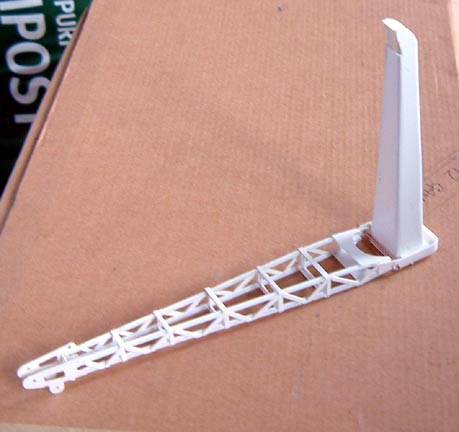
| The main upright of the crane was cut out of four sections of plastic card, near to each edge was glued a strengthening piece of plastic, the holes were drilled for the wheels and the derrick bottom fixing assumedly. Bending the largest piece of plastic near to the top, I then glued the two side pieces either side of it, when dry I glued the fourth section into position. | |||||||||
 |
|||||||||
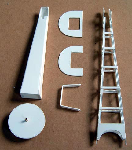
| Next was to make the base for the crane and the working platforms, these where then glued in to position under and around the main upright, the hand controls and the small motors were fitted, the whole thing was then painted and left to dry. I made some small pulley wheels with the help of my punch set out of plastic card, I drilled them and added the shafts, these were then put in position and the wire rope attached, also a small pulley wheel for the main lift section. We now have to do it all over again for the second crane. | 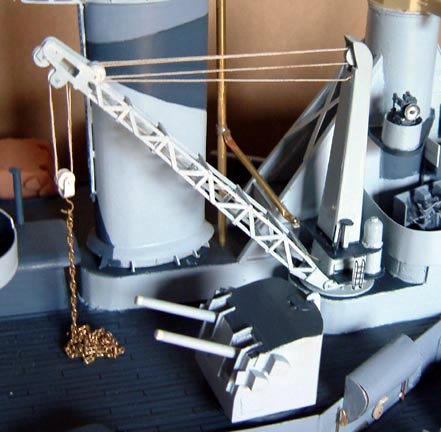 |
||||||||
 |
|||||||||
 |
|||||||||
| Happy modeling. Ron H. | |||||||||
|
on to part 10 |
|||||||||