|
| Fujimi released its long awaited 1/350 kit of the venerable
Imperial Japanese Navy aircraft carrier Kaga in May, 2015. They also
released two separate sets of photo etch and a set of wood planking for
its flight deck. I dont own the kit or those photo etch sets, but
from what Ive seen (admittedly mostly online), the kit appears to be quite
large and somewhat complex, as is the accompanying Fujimi photo etch sets.
Tetra Model Works is a relatively new South Korean company, established in late 2013. They got their start producing photo etch parts and accessories for 1/35 scale AFV kits. As those products were well received by the market, Tetra also began offering photo etch items for 1/72 scale aviation and 1/700 and 1/350 scale warship models. Apparently, Tetra felt there was room for improvements in the available
photo etch and accessories for the new 1/350 Kaga kit, and prepared a comprehensive
alternative set. This Tetra set was released in February 2016.
|
|||||
| Set Components | |||||
| I suppose that, technically, this is a mixed media set.
While brass metal sheeting and parts predominate to an overwhelming extent,
there are also stainless steel frets, thin wood flight deck planking, white
metal, and resin parts. The brass sheets are 7.25 x 3.75 in length and
width, 0.006 thick, relief etched and all protected by flat sleeves of
clear acrylic or cellophane. The stainless steel sheets are a little larger,
also relief etched and inserted into cellophane sleeves, as are the flight
deck planking pieces. The other brass parts are turned brass. All the other,
smaller parts are bagged in separate polybags.
Ill do my best to identify the significant components on each sheet.
Many of the frets carry close to one hundred pieces each. My ballpark estimate
is that there is close to one thousand individual parts in the entire set.
|
|||||
| Box | |||||
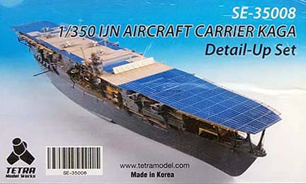
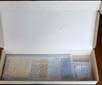
| The set comes in a heavy duty, corrugated cardboard box,
which is really a side-loaded, tab lock mailer, approximately 16 x 6 x
1.75, topped with a photograph of the set, and shrink-wrapped. All of
the contents were further wrapped in light bubble wrap.
I mention the packaging because my sample took quite a hit during transit, despite being shipped within a larger mailing carton. The cardboard cover was actually punctured, but the contents inside remained intact and undisturbed inside the bubble wrap. I would say that this has proven to be a smart packaging choice by Tetra. |
 |
||||
| Brass Parts | |||||
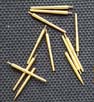
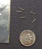
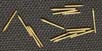
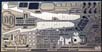
| The kit comes with a number of turned brass parts. All are packaged
in individual polybags:
1) 127mm barrels 4 short and 12 long. The shorter barrels fit into
the two power turrets that were placed on the starboard side, aft. The
others fit the standard open 12.7cm HA (High Angle) AA mount.
|
 |
||||
|
|||||
| 015T (Sus) A.part | |||||
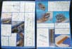
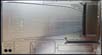
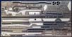
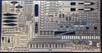
| This is a large fret comprised of what I believe is stainless steel.
The entire front portion of the flight deck, which was comprised of metal
plating, is replicated here, complete with plate seam lines, tie-down depressions,
and #1 elevator, which can be removed. This piece alone comprises slightly
more than 25% of the entire flight deck. Also included on the fret are
elevator #s 2 and 3, mounting rings and covers for the hideaway searchlights,
a crash barrier, the arrestor cables, some small vents, and some additional,
standalone plating for the flight deck.
The instructions arent at all clear about how best to affix the metal to the plastic flight deck. I assume that some sort of cyanoacrylate cement would work best to insure adhesion. I also think that the some of the plastic deck detail might have be sanded away to improve the fit and adhesion. |
 |
||||
| 015T (Sus) B.part | |||||
| This is another large stainless steel fret containing the aft, metal plated portion of the flight deck. Like the bow section, it has plating seam lines, tie-down depressions, and a round down for the very aft end of the flight deck comprised of treaded plating. This section makes up almost another 20% of the flight deck. Also included are more standalone portions of flight deck plating. | 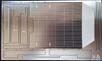 |
||||
| 015T (Brass) C.part | |||||
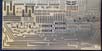
| This is a sheet containing a wonderfully detailed forecastle deck and the entire raised portion of the boat deck that sits aft. Both have raised lines representing linoleum tie-down strips. The anchor deck portion of the forecastle deck is covered with treading. The boat deck has fold down portions to represent the outmost support trusses, with lightening holes. Other parts include two different sizes of hawser reels, various boat chocks for the ships boats, deck railings, the aft leadsman platform, an enclosed lookout/docking station, and some cross braces for the aft flight deck pillars. | 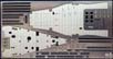 |
||||
| 015T (Brass) D.part | |||||
| The fret carries replacements for the four large, aft flight deck supports, some small platforms and ladders that are attached to those same supports, latticework and trusses that make up the both the cantilevered and athwartship boat cranes that hang over the aft boat deck, the corresponding crane hooks, a substantial support girder for supporting the very aft end of the upper hangar deck, some overhead rails, some railings, the maneuvering light array, and the maneuvering signal baskets that hung down from the flight deck girders. Also included are support struts for the 25mm AA platforms that line the aft end of the flight deck. | 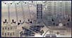 |
||||
| 015T (Brass) E.part | |||||
| This holds the latticework girders that support the aft flight decking, along with a perforated walkway, supports, and ladder that is affixed to the exposed aft end of the hangar deck. Also included are some of the devils claw chain stoppers used to secure the main anchor chain on the forecastle deck. | 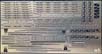 |
||||
| 015T (Brass) F.part | |||||
| Attached to the fret are the latticework girders that support the bow
portion of the flight deck, along with a small, linoleum covered platform
that was elevated over the forecastle deck, upon which was located a pair
of practice loaders for the 12.7cm main batteries.
Similar to the previous fret, there are walkways, supports, ladders and railings that are affixed to the exposed forward bulkhead of the enclosed hangar decks that jut out over the forecastle. There are also some parts for the forecastle deck; those being chaffing plates for under the anchor chains, some more devils claws for the anchor chain, perforated hawsehole covers, and main deck railings. |
 |
||||
| 015T (Brass) G.part | |||||
| This sheet contains the linoleum covered walkways that topped the platforms
for additional boat storage that was placed to either side of elevator
number three (one deck higher than the aft boat deck), along with trolley
rails and turntables for moving the boats. Also included are accommodation
ladders and davits, some observation platforms with supports and ladders,
railings, and an enclosed maneuvering station thats poised on the aft
end of the boat deck.
Additional are components for the funnel, including the internal uptake divider plates, a lot of handrails, and the components of the large support trestle used to support the funnel away from the hull. A number of pieces for the bridge island are also on the fret: linoleum decking for the exposed decks, hatches, railings, window frames, struts that anchor some of the radio aerials, an RDF antenna, and some small struts and perforated signaling platforms. |
 |
||||
| 015T (Brass) H.part | |||||
| The fret holds several long platform surfaces of covered linoleum,
treaded plate, and perforated gratings for the walkways that are either:
1) hung upon the side of the hull; 2) placed upon the sponsons that lie
along the upper portion of the hull; or 3) right below the edge of the
flight deck. They are accompanied by corresponding lengths of railing,
and triangular supports that line the underside of the suspended walkways.
Other pieces comprise the components of two, exposed radial engines and their test stands, which is a very nice addition to the set. Also included are several perforated gratings that cover some hull air intakes, two more accommodation ladders with davits, and some collapsible davits for large boats |
 |
||||
| 015T (Brass) I.part | |||||
| Fret I contains still more of the large and long linoleum, perforated, or treaded covered surfaces for various platforms and sponsons, along with corresponding railings and some support struts. Some turntables and trolley rails for the aforementioned aircraft engine test stands are included, as two of this frets platforms are meant to hold the stands. Other items include a small, enclosed lookout or maneuvering station for the port side, and four large, perforated struts that support the forward hangar decks | 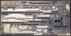 |
||||
| 015T (Brass) J.part | |||||
| Nearly half the fret is devoted to the 9m cutters: floor boards, thwarts
and foredeck, oars (many), rudders, double-sided davits and hull fittings,
lengths of chain used to suspend the boats from the davits, boat straps,
rope boarding ladders, hooks, doubled PE lines used to secure the davits,
and optional PE rope falls for displaying the boats in a more fully suspended
stance. These are fully equipped boat stations.
The remaining portion is comprised primarily of the grab rails that line that outside of the two storey hangar deck structure at the bow, assorted hatches for same, some railings, grab rails for the 12.7cm gun sponsons, and the two and four light landing light arrays for the aft flight deck. Another pleasant surprise is the addition of numerous wooden benches, for the sponson decks that ring the flight deck. |
 |
||||
| 015T (Brass) K.part | |||||
| Like the J fret, a large portion is devoted to ships boats; in this
case, the larger 12m motor boats, launches, and daihatsus. Included
are boat booms, boat boom ladders and PE rigging to display the boat booms
in an extended position, small boat decking and deck houses, low deck railings,
canopy frame ribs for the open launches, exposed engine assemblies, propellers
and rudders, boat cockpit components, skylights and frames, life rings,
jack staffs, and floor boarding for the diahatsus. Essentially, each ships
boat becomes a miniature model of its own.
Other goodies include more hatches for access to the hangar decks, two sets of twin propellers and tail fins for modified Type 91 aerial torpedoes (two included in the set),, two torpedo trolleys for the flight deck, boat booms with PE rigging, PE rigging and spreader bars for the radio masts, foot ropes and stirrups for the radio mast yardarms, two types of latticed aerial mast bases, fittings and the large, sprocket-like mechanisms that were used to raise and lower the radio masts. |
 |
||||
| 015T (Brass) L.part | |||||
| These are mostly brass secondary struts, primarily attached between the large flight deck column supports at the bow and stern, and the underside of the flight deck. There are additional strut supports for some of the secondary sponsons hanging off the hull, and also some rain runoff piping to be mounted mount on the outside of some of the aft flight deck pillar supports. | 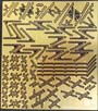 |
||||
| 015T (Brass) M.part | |||||
| In no particular order, there are: large mesh flight deck nets meant
to prevent aircraft from falling onto the sponsons and platforms placed
just below the flight deck amidships and aft, small mesh netting placed
at the bow and stern of the flight deck for personnel protection, the supports
meant to hold on the netting in place, and the large, perforated windscreen
that acted as a windbreak on the flight deck when raised, with the underlying
truss structure and PE guy wires.
The other parts of the fret are meant for the twin 25mm AA mounts: base rings, base carriage, elevating gear, foot pedals, and curved gravity feed ammo boxes for the guns. |
 |
||||
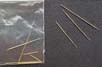
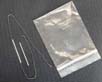
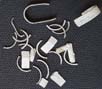
| Metal Chain and Plastic Rod | |||||
| One blackened metal chain for the anchor chains, 10 1/8/258mm long,
to be cut into two lengths. Its at least 32 links to the inch; maybe more.
It certainly looks to scale.
Two lengths of white styrene rod each is 32mm in length. They appear to be 0.025 in width; possibly 0.3, and meant to be used as some auxiliary funnel piping. The Tetra instructions show them sticking out perpendicular to the hull, in-line horizontally with, and immediately aft of, the funnel. The tips are meant to be curved downward. |
 |
||||
| Resin | |||||
| Blast bags ten, for the single 203mm barrels. | 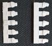 |
||||
| White Metal | |||||
| 1) Rolled hammocks for splinter shielding - nine pieces meant for the
bridge structure, of which six are rolled vertically and three horizontally.
All need to be painted off white with tinges of tan to represent bleached,
and (if desired) weathered, canvas.
2) Sandbags for splinter shielding fourteen pieces formed in semi circles stacked two high and meant to be mounted on the outside of the aft 25mm gun tubs, and directors. These would probably be more a tan colored canvas. |
 |
||||
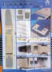
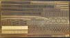
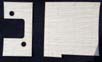
| Wooden Deck | |||||
| A replacement for the kits flight deck planking is provided,
composed of five sections of a very thin, laser cut wood, backed with an
adhesive and protective liner. While not a big fan of applied wood
decking, I will say that the planking is rendered very nicely, with subtle
seams and planks that are 0.3 inches wide, which scales out to 10.5 wide
in 1/350. I dont have the Fujimi 1/350 Kaga kit, but if its flight
deck planking is the same, overscale 0.4 inch (1/350 scale = 14 inch) wide
as in their 1/350 Shokaku, Zuikaku, and Hiryu kits, then this is a very
welcome improvement.
The planking pattern is symmetrical in nature, repeating every fourth plank, an improvement over the plastic kits pattern of every third plank. The effect is more accurate, aided in part because the planks are thinner in width, as are the seams between planks. Tie-down holes are also etched into the planking. Cutouts for two of the elevators, hide-away searchlights, wind screen and several areas of deck plating exist. The photographs are a bit washed out with regard to color. While very light, the wood is richer in actual appearance. |
|||||
 |
|||||
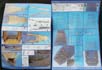
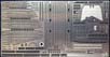
| Instructions | |||||
| The instructions are as comprehensive as is the PE. There are fifteen pages of 8.5 x 11.5 instructions. They are a combination of individual part assembly photos, three point perspective diagrams of part assemblies, photographs of some fully assembled components, and full color photographs of unpainted parts installed on a Kaga model as well as in standalone configurations. The only thing missing is a full listing or graphic of all the components, but that graphic can be seen on their website here. | 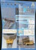 |
||||
Careful attention MUST be paid. There are a great many parts and photos, and each photo can have several designations that apply to a multiple of different frets upon it. So, a thorough review of each step is warranted. The instructions also depict the kit is various states of assembly, so some coordination of the build in conjunction with the application of the photo etch is probably necessary It would probably help greatly to make use the additional photographs listed in the two links above, particularly for placement. |
|||||
| Fit | |||||
| I dont have a Kaga kit to spot check anything against, so this is an open question. It certainly looks like the components have been carefully engineered to fit, but only an actual build can confirm this. Perhaps a board member can report in on this point. | |||||
| Closing thoughts | |||||
The sheer number of parts, coupled with the extensive instruction
sheets, can seem a little overwhelming at first. Theres no getting around
the obvious: its a very big, all-encompassing set of photo etch for a
very large 1/350 ship model. Fortunately, repeated study of the PE frets
and instructions can give way to a high degree of clarity. (This was true
for me; I believe it will apply to most other modelers.)

As stated earlier, I think it important to try and map out the modeling process in conjunction with the kit instructions, step by step. More than a few kit pieces are replaced by PE, so one wants to minimize the possibility of installing bits either too early or too late in the overall building process. Cross-checking part configuration and placement against Tetras own website photographs (and on the MW Forum ) will help immensely, in my opinion. This is an extremely comprehensive set. The only thing thats missing that I can see is a degaussing cable for the ship, as the kit does not have one molded on. Such a cable was installed in late 1941. Another nice to have might have been the inclusion of some detailing for the aircraft, but I note that Tetra does make a separate set for just that, as do some other photo etch manufacturers. (Further note: There is a limited edition version of the Kaga set that does include aircraft parts, but these can be hard to find at this point.) Otherwise, the set seems complete. This is not a set for a photo etch novice. However, with patience and careful planning, an exceptionally detailed Kaga model can be produced. Thanks to Tetra for the review sample. The website doesnt list their distributors, which I hope will be corrected at some point. Among the distributors that I do know of are Freetime Hobbies and Hobbylink Japan. According to the Tetra website, the suggested MSRP is US$280.00. |
|||||
| This is an in-box review showing the kit contents. We welcome your input and comments in the review section of the forum especially if you can share details about fit, ease of assembly and accuracy. Click the logo on the right to join in the discussion. |  |