| Many of the recently produced kits are released as full hull only, leaving the water-line/ diorama builders in a bit of a bind as how to show them 'at sea'. I've used a couple of different methods, including the little rotary saw on my Dremmel, but the completed cut line always ended with unsatisfactory results. So after some thought, I think I've come up with a process that, (though may take a little longer - the Yahagi hull took me 1.5 hours, not including glue drying time) adequetly solves the straight cut problem and the constant danger of using a Exacto blade scapel knife to repeatedly score a line. So here is a basic step by step on what I did to cut down the Hasegawa's Yahagi hull. | |
|
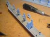
The two hull halves fresh off the sprues. Notice the internal hull bracing locator holes. The water-line is located somewhere between the two upper and lower points and as I have to know where to cut the bracing pieces, I will have to mark the line. |
 |
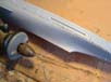
| On this hull and many of the Japanese kits, there is a
very faint but raised water-line and using a sharpened pencil, carefully
run it along this rib. On other kits without a dicernable line, I use the
1:350 scale colour chart supplied to measure and mark it onto the hull,
then lay Tamiya tape along the upperside of the line.
Once I am happy with the finished result, I'll drill a 1mm hole at each bracing point, thereby able to see where the internal braces must be cut. |
 |
 |
|
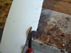
| Now seeing that the center rib on the internal braces mark
the water-line, using some flush cut pliers, remove the lower half of each
brace, double-checking that none will extend below the cut line.
|
 |
 |
|
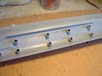
| This is where I have to do more customizing to stop the dreaded 'banana'
effect that may occure at a later date. The 'Banana' effect is what could
happen (as it did on one of my previous builds) when the bow and stern
lift a couple of millimeters because of the relatively thin flat base to
be added. So now I add a 5 or 6mm square wooden strake along the entire
lenght of the base plate to keep it rigid and flat. To do this, each hull
brace must have the diamentions of the strake cut out of their centres.
As this is done, I glue each into it's hole and make sure they are lined
up correctly.
|
 |
|
Once I am happy that everthing is correctly aligned, it's time to mate the hull halves. This I leave overnight to dry. |
 |
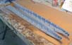
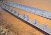
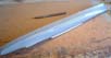
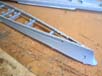
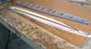
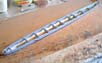
| This process is the most critical and the most boring.
Using a 1mm drill bit, I drill holes the entire lenght(under the water-line)
of both sides of the hull, using an Exacto knife to 'lathe' off any build
up of melted plastic that appears on the drill bit. Any build up of melted
plastic will make the hole too big and extend over the cut line. Each holes
outer diameter must not extend above the water-line, so great care is needed.
I space my holes apart, the same diameter of the drill bit, 1mm.
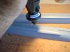
This next process I discovered after some trials and errors, but I found it works quite well if care is taken. Using the top half of a broken 1mm drill bit in my Dremmel, I carefully drag the spinning bit from hole to hole therby cutting/ melting a line. Not being heavy handed, after a number of passes, this will cut through the hull leaving a few melted joins which can be cut with the Exacto later. Once again, any build up of melted plastic on the drill bit (router) must be shaved off so as not to cause an exessive cut diameter. |
 |
 |
|
 |
|
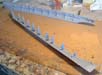
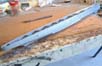
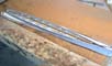
| Once the routing is done, it's a simple matter of cutting the remainig joins and separating the halves. The finished results might not look too promising at first, but having the cut line as even as possible is what I'm trying to achieve. The next step is sanding the cut line flat. This I do on my table belt sander using a fairly course grade of abrasive. Care must be taken here as well because I only want to remove the half holes and no more. With the belt spinning, I gently lower the hull onto the table holding it in a flat position with my hands covering as much of the ships area as I can manage. This is done to keep the pressure on the sanding area as even as I can get it. All I do now is hold it there, turning it 180 degrees every few seconds. If the belt starts to bite into the hull, I know I am applying too much pressure and back off. I keep checking the progress all the time and continually test it on a dead flat surface. | 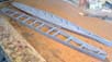 |
 |
|
 |
|
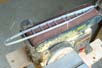
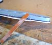
| Next step. After I am happy with the sanding results, It's time to cut the base plate. Here I use some 2mm acrylic sheet and it's a simple job of holding the hull completely still and tracing it onto the sheet. I don't do it exact and leave a bit of overhang all the way around. | 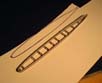 |
| Using a dead flat hard surface, I fit the base plate stiffener into the hull brace cutout slots and sit this onto the base plate. Here I will add a few drops of superglue along the wooden strake and base plate, fixing it into position. Once set, remove the hull and run superglue the entire lenght of the strake. Again let set, or like me, hit it with accellerator, then fit the hull back on top. Here I sometimes use clamps to hold it there, but either way, hold the hull perfectly still and apply superglue to the inside mated areas of the ship and base. Once again, it is critical that whe whole assembly be held dead flat and still until completely dry. Once glue has set, I will stand the assembly on its nose and squeeze heaps of superglue along the mated join and let it run the entire lenght of the inside join, sealing all areas. | 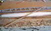 |
 |
|
 |
|
 |
|
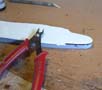
| Now comes the time for trimming the excess base plate and flush cut pliers are needed. Because the pair I have are pretty short nosed, I heed to make verticle cuts the entire lenght so the excess can be removed evenly. To smooth the edged once the trimming is done, I use the tip of my knife to scrape the edge until it's flush with the hull edge then finish off with a coarse emery board. These steps must be done with care so as not to remove or damage to any of the hulls details. | 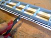 |
 |
|
 |
|
 |
|
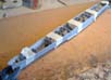
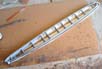
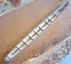
| Here basically is the finished result. You may notice that the base plate strake is made of two pieces, that's because I had run out of the material to do it with in one piece. I joined the two pieces by drilling a hole in mated ends and gluing in a metal rod. It worked nicely and is as rigid as a one piece lenght. One thing I forgot to show for the process was the test fitting of the decks. This I did throughout all stages to make sure everthing fit properly up to the end result. | 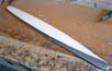 |
 |
|
 |
|
 |
|
More
of Kym Knight's work.
Updated 2009

© ModelWarships.com