I can’t tell you the number of times I hear that resin ships are scary or too difficult. It’s all hype or in this case anti-hype. True the average resin ship is more expensive than an injected kit of similar size... until you figure in the cost of adding PE and upgrading many of the poorly detailed or overscale plastic parts with aftermarket parts. If you want good detail, included PE and a better selection of subjects, resin ships are the way to go. You’ll use the same basic techniques as you would on plastic with a little more cutting and different glues. You must also prime resin. No big deal! The glues you need are high quality epoxy and CA, do not cheap out and buy hardware store 5 minute epoxy, it’s not strong enough and sets too fast. You will also want a good lacquer primer, I prefer DuPont Lucite 131S thinned with Mr. Color Thinner. Other than that you can use the same paints and most of the tools you’re used to using on plastic.
Other excuses for avoiding resin ships tend to be along the lines of: It’s so easy to screw it up. Plastic is just as easy to screw up. It’s messy with all the sanding you have to do. I’m going to show you how to eliminate most of the mess just by working smart. Resin dust is toxic! WRONG! Properly cured resin does not produce toxic dust. Simple precautions such as a dust mask and wet sanding are all you need. I will warn you that resin dust, like all dusts is a mechanical hazard, but so are pollen, flour, sawdust and styrene dust; unlike those dusts resin dust does not tend to explode when suspended in air and a source of ignition is available. Some people are allergic to resin dust but people are allergic to all kinds of things, so unless you’re one of that unlucky set don’t worry about it.
The kit I’ve selected is a Somers Class destroyer from Yankee Modelworks. The techniques I’ll demonstrate can be used on any resin ship. Even the armor modelers will find some of them useful for the resin conversions and kits with large pour plugs. Aircraft resin parts tend to be a bit too small for some of the techniques but someone may figure out how to modify the techniques for use on those smaller parts. Keep in mind, no kit is perfect and injection kits have their typical problems while resin kits have another set. Normal defects for resin kits are pinholes, voids, flash, warped thin parts and differential shrinkage. I will point them out as we go and show you easy fixes. I’m going to assume a few things like a basic set of modeling tools and an intermediate skill level. I’ll assume you can successfully build and paint an injected plastic kit, what I’m going to do is show you a few tricks applicable to resin. Now on to the model....
Fig.1The box, deceptively plain looking.
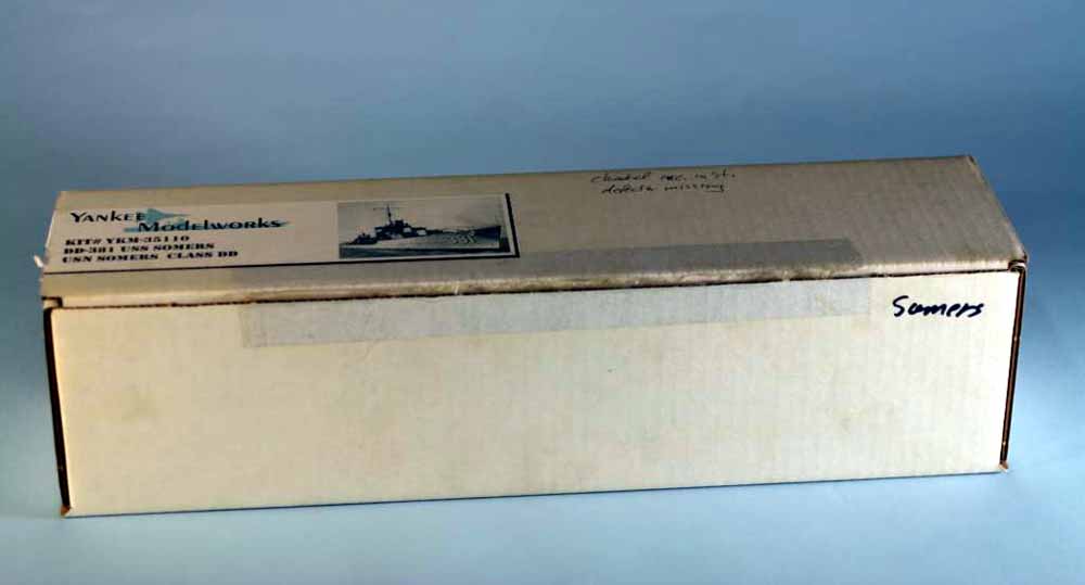
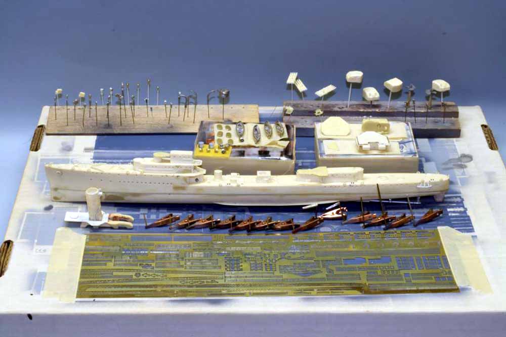
Fig.2 What’s in the box, the two hull halves, bags of resin and white metal parts, PE fret, decals and instructions. Hulls and large resin parts are normally wrapped with bubble-wrap and the box is filled with Styrofoam peanuts to help prevent damage. Should you have a damaged or majorly defective part, contact the manufacturer, most of them are very good about replacing them.
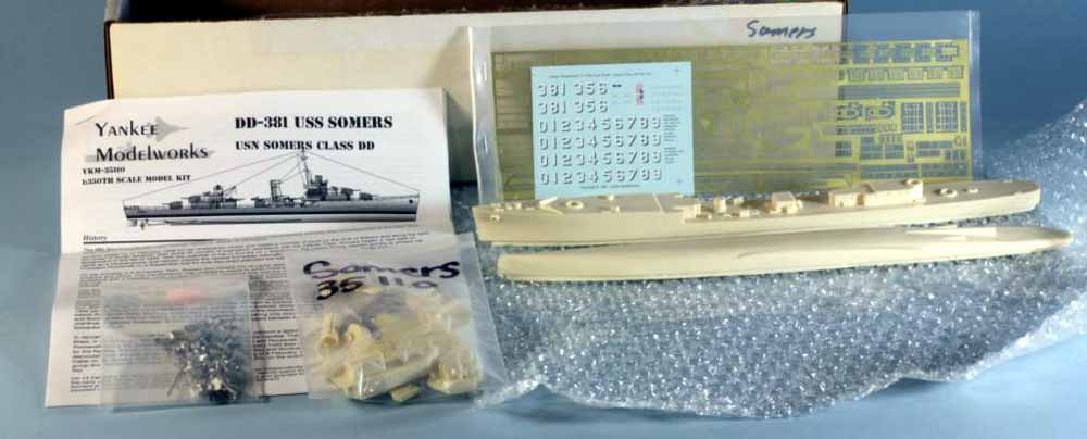
Fig.3 Prep time, washing the resin. Resin kits are cast in silicone rubber molds, the molds themselves leach silicone oil to their surfaces, kit manufacturers usually use a release agent as well to improve the release of parts and extend mold life. You want to get all that off before you do anything else! In most cases simple dish liquid is sufficient but I prefer to get a little more aggressive and use Westley’s Blechewhite tire cleaner, it is made specifically to strip the silicone based tire shine products off tires. Just hose the small parts down in a plastic tub and let soak 15 minutes or so then scrub with an old toothbrush and rinse with hot water. Repeat for the hull parts, usually I hold them in my hand. A word of warning, WEAR RUBBER GLOVES! Blechewhite is too harsh for much skin contact and the label clearly warns you about it, it smells and looks like Windex on steroids. Simple Green will also work but the smell gags me.
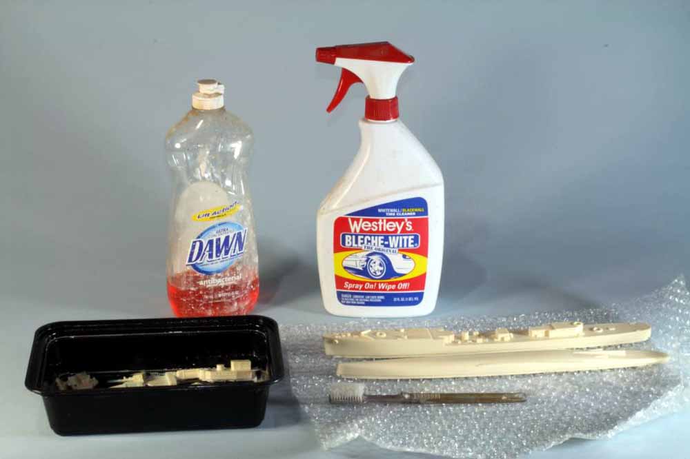
Fig.4 Parts soaking in Blechewhite, it doesn’t take much.
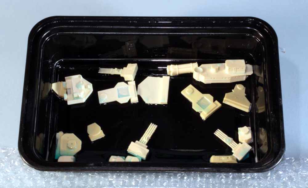
Fig.5 Now is the time to inventory the small parts and check for show stopping defects. As you inventory and inspect them, sort them by logical types into a compartmentalized bin as shown. It’ll help later in the construction because you’ll know where the parts are.
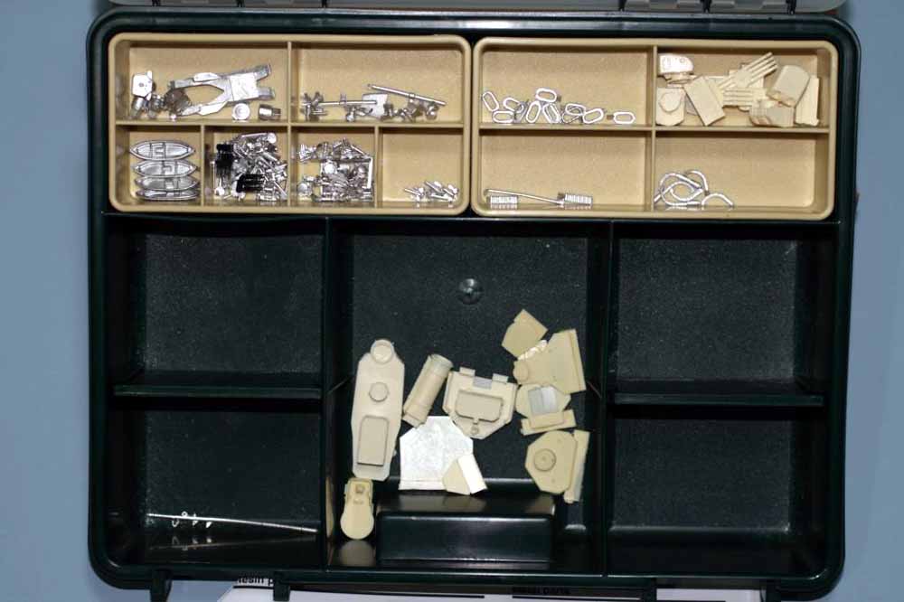
Fig.6 Next we’ll tackle the scariest part of the build…..prepping the hull for gluing. Some kits have a large pour plug you need to remove from the hull halves, don’t try to razor saw or sand it off, that’s just too messy and labor intensive. Instead we’ll work smart. Take a coarse razor saw and carefully cut a kerf along the base of the pour plug, it only needs to be 1/16” to 1/8” deep. Next flood the kerf with india ink, work it into the kerf with a cheap paintbrush then let it dry. This will provide a positive depth indicator for the next step. Trust me, follow this method for larger ships like cruisers and battleships and you’ll be amazed how fast it is.
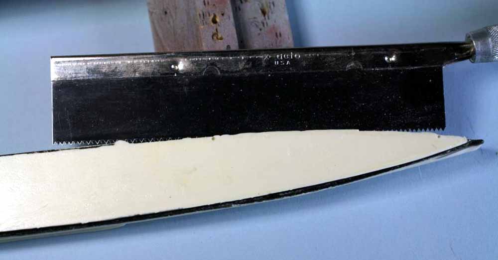
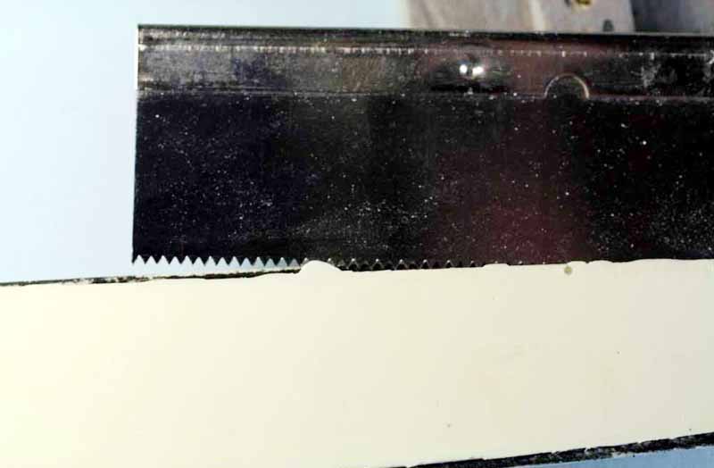
Fig.7 The “magic” tool, the Forstner bit. These bits leave a flat bottomed hole with a center dimple, as long as the point that creates the dimple has solid resin to start guiding the bit, you can overlap the holes by just under half the bit diameter. The bits cut slower than regular bits and produce shavings rather than dust. The big trick is selecting the right diameter for the hull, the bit to the left is as wide as the hull, that’s too wide. The bit to the right is a better choice for this hull. You can use them in a drillpress, corded drill or at least a 12V cordless drill. The bits take more torque than regular bits so cheap cordless drills just won’t cut it, even my 12V drill will not reliably power the larger bit when I work on larger hulls.
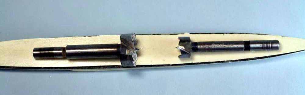
Fig.8 The lower hull with most of the pour plug hogged off by drilling overlapping holes with the Forstner bit. The trick is to start your holes with the edge of the bit over the edge of the pour plug but not outside the hull margin, drill until you hit black (that’s the kerf we cut and filled with india ink). You may note the hole bottoms aren’t perfectly level with each other and the dimples, no big deal. The important areas are the edges of the hull where they’ll mate, as long as those are good and flat the minor dimples and hollows are actually a good thing for epoxy bonding. Notice the shavings, probably 98% of the shavings created are in the frame. A very small and simple mess with no fine airborne dust to clean up. We’ll take of the remaining bits of pour plug and the very bow next.
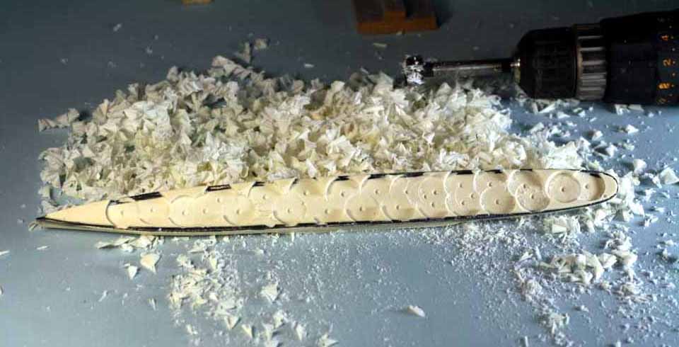
Fig.9 Literally three minutes with a coarse razor saw and the last bits of pour plug, including the chunk at the bow are gone. By using the coarse razor saw you will avoid creating fine dust, what dust there is will just fall to the bench top.
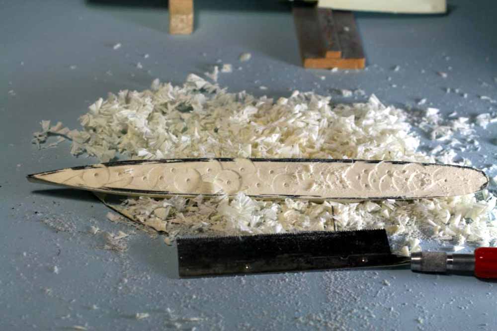
Fig.10Repeat the previous steps for the upper hull half. To avoid damaging any cast on details place the part on balsa blocks, make sure the blocks do not bear on delicate details. 10b is a side view showing block placement to avoid details. It is important to move the blocks as you drill so the resin to either side of the pressure zone is supported. On larger hulls I actually tack glue, using white glue, balsa blocks in place before I start drilling.
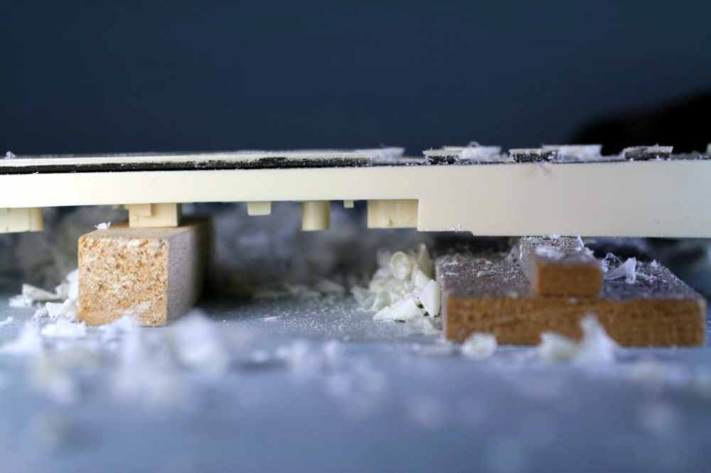
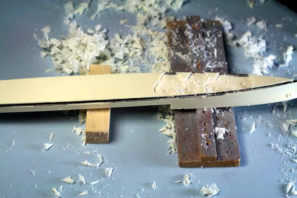
Fig.11 The next “magic” tool, a simple piece of 3/8” or ½” thick glass plate with 220 grit aluminum oxide sandpaper rubber cemented to it. Because you’re going to be working slowly and the grit is fairly coarse, dust should not be a major problem and there just won’t be that much dust. This is the only time I dry sand resin. Use circular motions and flip the hull end for end at least twice. Apply just a little pressure and sand, check your work every fourth or fifth circle. Stop when you have a line of bright, flat resin showing along the entire hull edge.
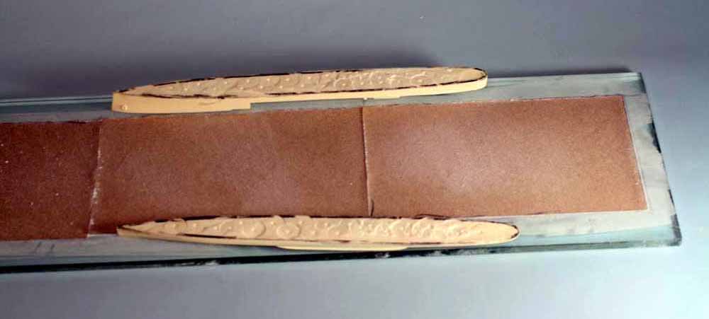
Fig.12 Both hull halves are done. That’s the total dust created by both parts. I told you there wouldn’t be much dust.
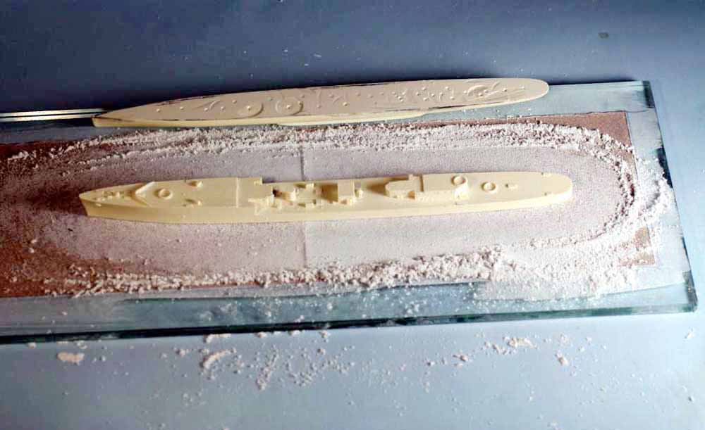
Fig.13 Two hull halves ready to glue. The stern ends have a little more surface irregularity but it’s all where it doesn’t matter and will actually provide some mechanical “tooth” to the epoxy bond. Notice that the hull edges are flat and sharp for the most part. Between the epoxy used to bond the parts and the inevitable putty work along any major seam the slight irregularities along the outer edge won’t show on the finished model. You will want to rinse the dust in the dimples out before gluing. At this point the total labor time for this kit from opening the box is 45 minutes.
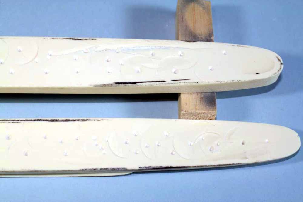
Fig.14 Clamps? We don’t need no stinking clamps! Why use clamps that can slip or due to wrong placement crush detail? In fact , we’re going to make sure this hull never comes apart. Machine screws are the next “magic” trick. That’s right, we’re going to drill and tap this hull and hide the screw heads under turrets and deckhouses. I told you it was simple technology, it doesn’t get much simpler than the lowly machine screw. For destroyer sized hulls I find 4-40 screws to work most of the time, rarely I have to go smaller and use 2-56 screws. For cruisers 6-32 and 8-32 provide more than enough strength and clamping force but if you can hide a 10-32 that’s even better. 10-32 and 12-24 are best for battleships. Here you see a battery drill, tapdrill with taps, drill for through holes and the taped together hull with hole locations marked as X’s. Since the lower hull is very thin and has a simple contour I’m just going to drill right through both hulls with the tapdrill while they’re taped together. A small dab of putty and quick swipe of a sanding stick will hide the holes on the bottom. The slight darkness along the joint is just a bit of india ink stain except at the very bow where a little of it is shadow.
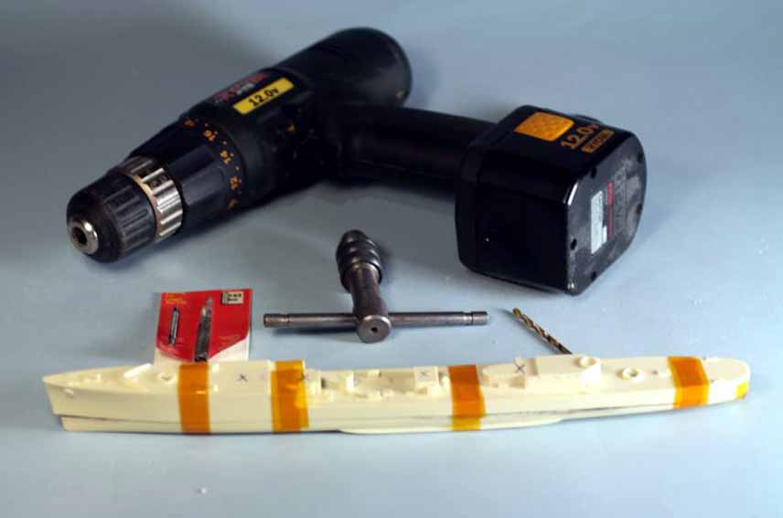
Fig.15 Drills and taps. The tap on the left is an old broken tap I ground flat on the end with a slight taper to the first thread to allow it to tap blind holes. The tap on the right is a normal tap with a long taper for easily starting holes. The darker drillbit in the package is the tap drill while the golden colored bit is for the through holes.
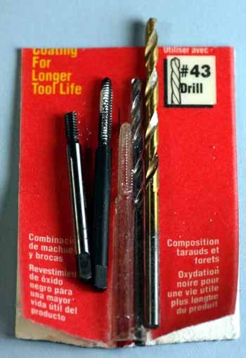
Fig.16 The hull taped together and marked. The hole locations and the counterbores to recess the screwheads will all be hidden by a turret or deckhouse. I use Kapton or polyamide tape for this since it holds well and does not stretch.
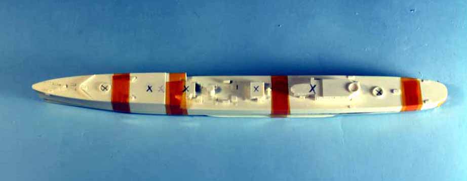
Fig.17 Remember my comment about differential shrinkage? There it is! The lower hull is a bit shorter than the upper and has a slight sideways warp at the bow. After drilling and tapping the holes I’ll cut the bow off the lower hull and glue it in place later.
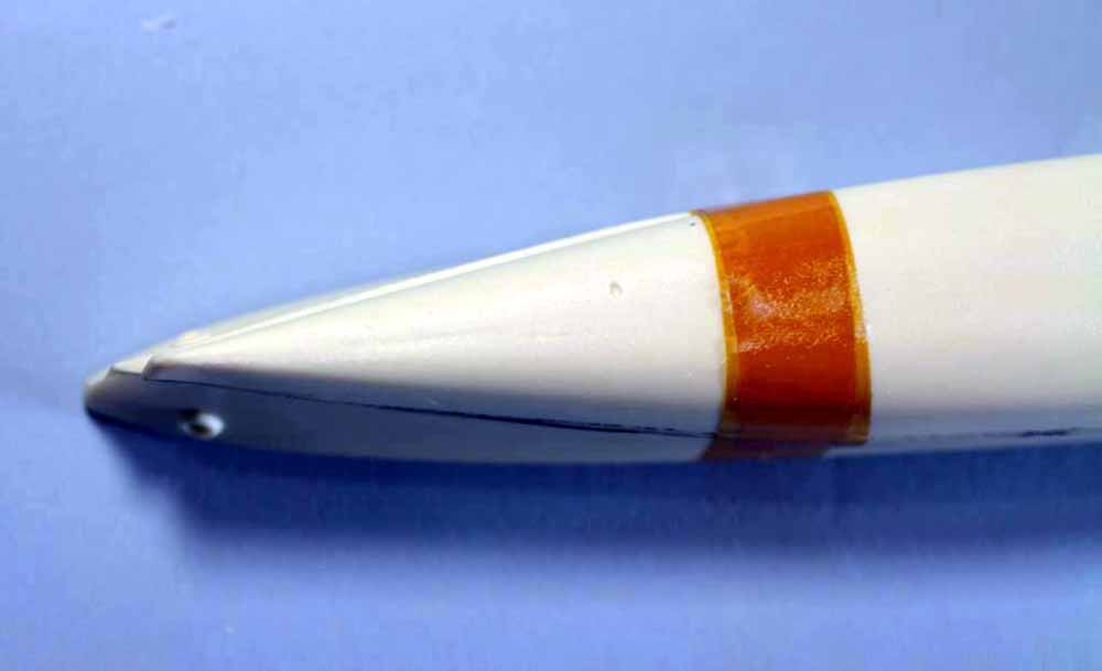
Fig.18 The critical alignment point on this hull is the stern. You want it lined up as perfectly as possible. I start by applying the tape across the stern seam, then do the tape wrap around both parts. The small X is where I intend to drill up and install a screw from underneath, hiding it is as simple as a dab of putty and a quick sanding.
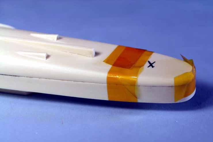
Fig.19 All holes except the one under the stern are drilled, tapped and on the upper hull drilled again with a larger bit to allow the screw to pass through freely. The tapped holes in the lower hull are circled in black to show where they are, you only need to tap the lower hull holes (the reverse will be true when you drill the hole under the stern). To determine the proper drill to use for the through holes google “tap+drill+chart”, the best charts will have columns for tight clearance and free slip, use the latter. The next step will be counterboring the holes by hand and cutting the brass screws to length.
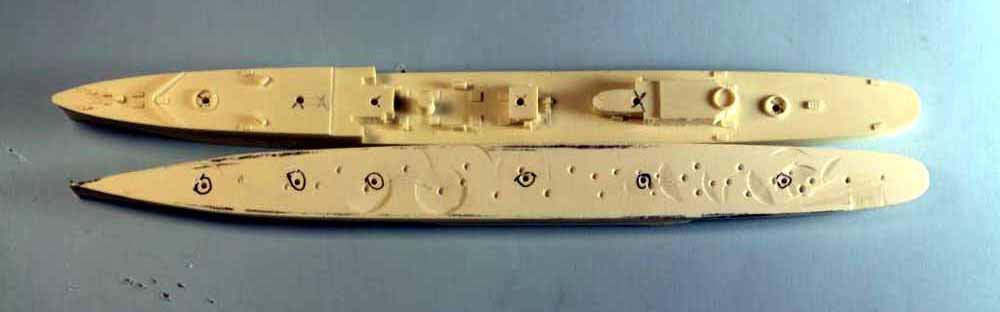
Fig.20 Use a drill a few thousandths larger than the diameter of the screw head and twist it by hand to counterbore the holes as shown. The counterbore only needs to be deep enough to have the screw head just below flush. Do not try to use power for this operation, it is very easy to go much too deep or even through the hull.
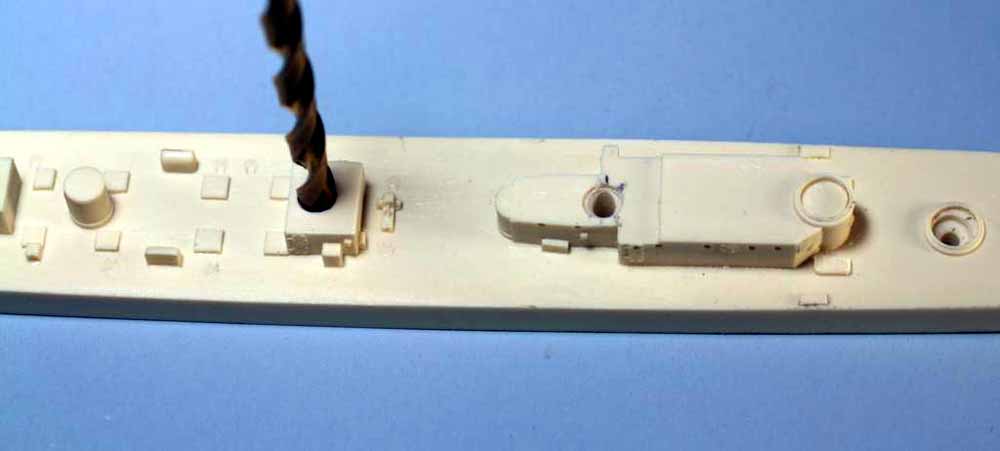
Fig.21 In many cases you will need to cut screws to length. You need a minimum of 5 full threads engagement but I prefer ¼” to 3/8” in resin (on large ships I will happily go deeper). Whatever you do, do not bottom out a screw in a blind hole, stop well short of the bottom. I find the easiest and cheapest tool to use is a standard wire stripper with a built in screw cutter. I have a screw threaded into the top at the 4-40 location and just above the word press is a previously cut screw. I have the hand strength to easily cut brass or mild steel screws in 4-40, 6-32 and 8-32 but I find from 8-32 up with mild steel screws it is very easy to get part of your hand caught as you squeeze the handle because you’re thinking force not finesse, in that case I use a hacksaw with the screw held in a vise.
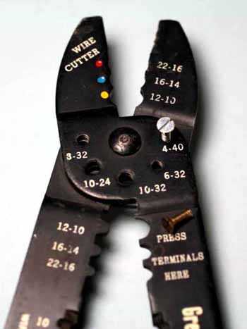
Fig.22 Upper hull with screws in place, note they are all below flush with the deck. Do not try to really tighten them, you don’t need that much force and risk stripping the threads in the resin lower hull. Simply snug them down with the torque you can apply with your thumb and one finger on the screwdriver, that is sufficient at this point. Double check your alignment after snugging the screws, now is the time to fix any problems. If there is a misalignment use a needle file to slot the through hole a little towards the direction you want to slide the parts, a little play won’t hurt.
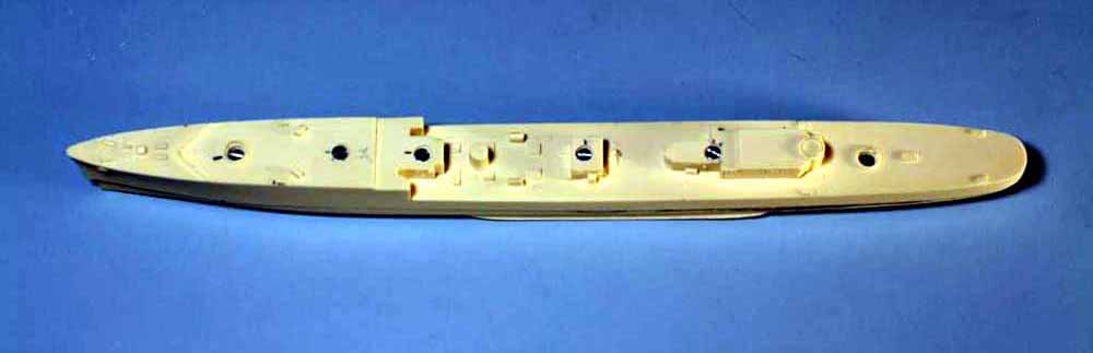
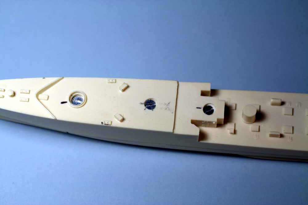
Fig.23 The underside of the stern with the screw in place. It is below flush and well away from the rudder mounting point, you’ll understand why when we mount the rudder later. A small dab of putty and a quick sanding will render the screw invisible.
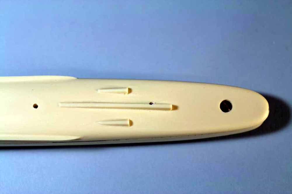
Fig.24 The underside of the bow showing two screw holes and the line I have drawn to cut the bow away. One reason I drilled through on this hull is to show you approximately how much room to leave between the foremost screw and the cutline. You want to leave sufficient resin forward of the screw hole to prevent a fracture later when you apply the final torque and to allow for a cavity I’ll describe shortly.
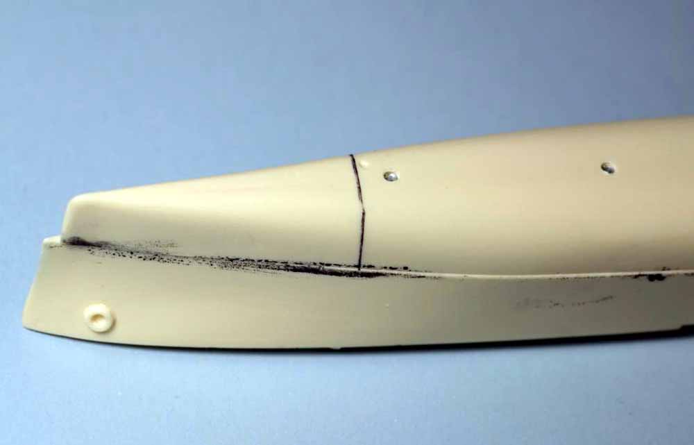
Fig.25 After cutting the bow off with a coarse razor saw file a chamfer on the edge of the mating face. Make sure to stop 1/16” to 1/8” from the outer edge. The purpose of the cavity thus formed is twofold. First to allow the epoxy used to bond the hull a place to ooze and not affect later gluing in that area. Second if, like this hull, there will be a significant gap that needs to be resin filled it adds a mechanical key for the resin to grab. Notice how close to the threaded hole the chamfer is, this is one reason to leave a good space between the hole and the cut.
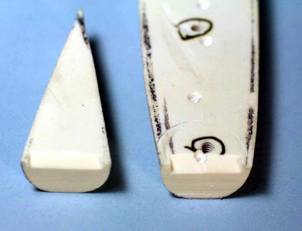
Fig.26 Here are two types of suitable epoxy for bonding hulls. The stuff in bottles is 30 minute epoxy made by National Hobby Products and is often relabeled for hobby stores. It is strong enough for destroyer and small cruiser hulls. It has a long enough working time for both but you’re pushing the limit on a cruiser. The box is Devcon steel filled epoxy putty, this stuff is extremely strong. It is suitable for all types of resin hull bonding and the aluminum filled version is USN approved hull patching material. It can be mixed by weight or volume, don’t be tempted to vary the ratio too far or it will set too fast or may not set at all. Mixed per the directions you’ll have an approximate working time of 45 minutes, you’ll need at least half of the time.
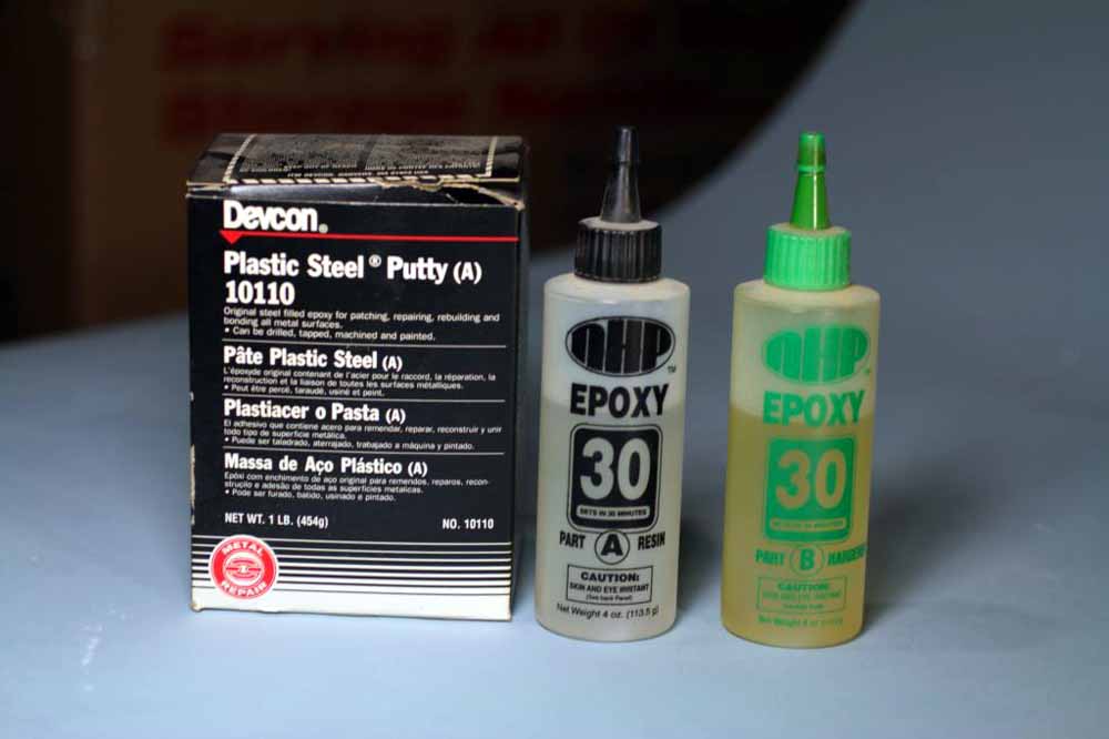
Fig.27 Make sure you have everything needed for gluing ready before mixing the epoxy. Here are what I consider the minimum tools and supplies: a disposable mixing cup, popsicle sticks for mixing and applying, a spatula for scraping excess epoxy, napkins for wiping the spatula, a screwdriver, the hulls, the screws in a tin where they won’t roll off the bench, 3 disposable gloves, q-tips and acetone for wiping the hull clean at the end. Make sure to leave yourself at least an hour of uninterrupted time before starting to glue the hull.
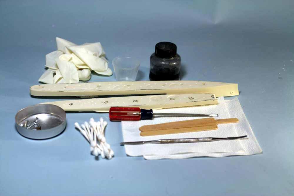
Fig.28 Now it gets messy. On the upper hull notice I slotted the forward most screw hole, it was too tight a fit otherwise. Also note the black line marked across the hull. The line is where the lower hull ends after cutting off the bow, do not forget this line or you’ll have a mess to clean up. The lower hull has been “buttered” with epoxy using a popsicle stick, you can see to the left the edge of one of the slight depressions from the Forstner bit. As thick as this epoxy is you can now see why I said not to worry about the uneveness in the middle of hull pieces. One advantage to this type of epoxy is it is thixotropic, that means it is a gel in its normal state but shear stress makes it behave like a liquid while the shear force is applied. You have now learned a new polysyllabic word to impress your friends.
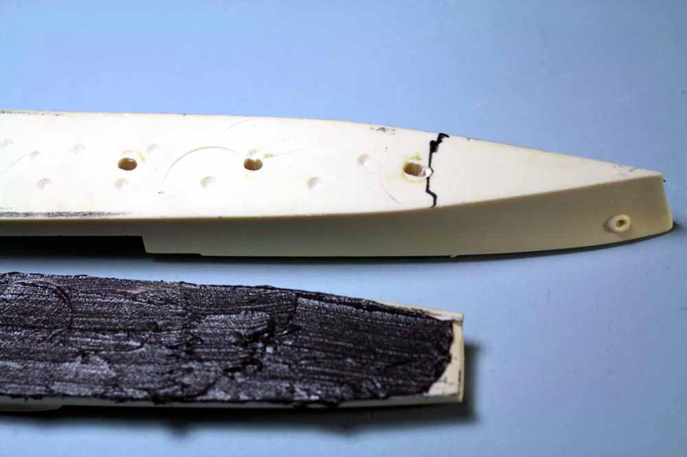
Fig.29 Both hull parts have been “buttered” and excess epoxy left in the mixing cup. Do not throw it out yet, save it to make sure of the cure. You can see how messy the epoxy is, the other type is more liquid and even messier. Aren’t you glad I told about the gloves? Try to only hold the messy hull parts with one hand so the glove on the other stays mostly clean, you’ll end up changing the messy glove in a few minutes. On both hulls I have stopped the epoxy just short of the cut at the bow, don’t worry some will ooze in there and even if it doesn’t we’ll fix the slight gap later. The next step is to mate the parts and snug the underside screw into place, just snug it for now. Install the topside screws starting aft and moving forward, just snug them down finger tight. Make sure the parts are aligned and snug the screws down using your thumb and one finger on the screwdriver, by now epoxy should be oozing out of the seam. Use the spatula and scrape the globs off, wipe the spatula on one of the napkins, don’t try to be too neat yet. Now go back and give each screw another ¼ turn, repeat the scraping. Let the hull sit for a few minutes, scrape then add another 1/8 turn torque to the screws, repeat scraping.
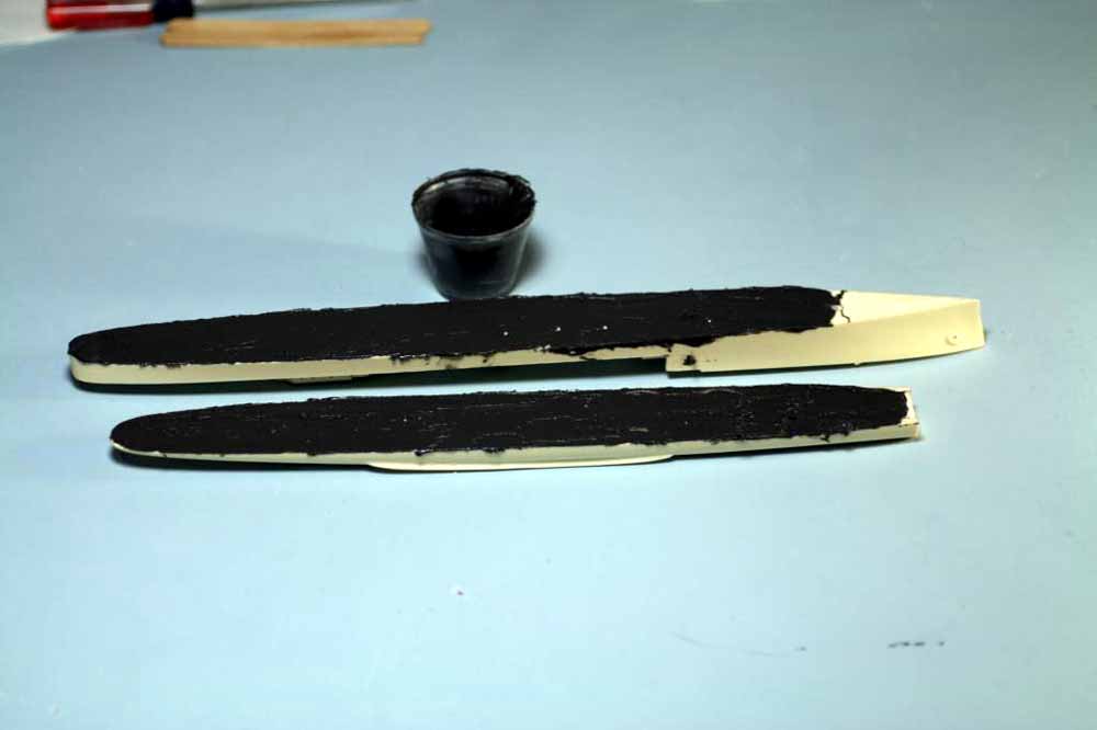
Fig.30 Here is the hull after the first tightening of the screws. My glove has some epoxy on it but by the time I finish scraping the major squeeze out off the hull it’ll be much messier. Notice how much epoxy has squeezed out along the seam.
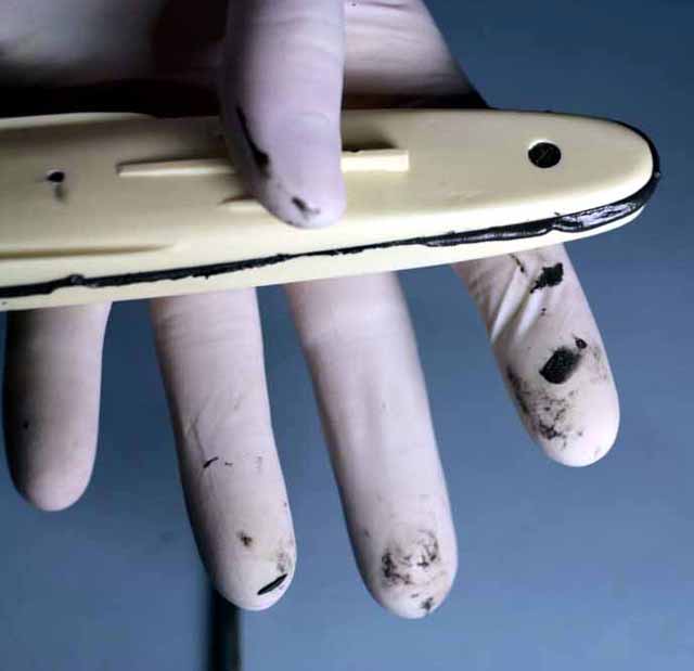
Fig.31 A view into the cavity, notice the tiny bead of epoxy that’s oozed into it. Since the epoxy isn’t beyond the edge of the cut you can just leave it alone, remember to check this spot before you think you’re done. You can see a line of squeeze out along the seam and the major drawback to drilling through the lower hull. The dot of epoxy on the lower hull is where the screw pushed some out.
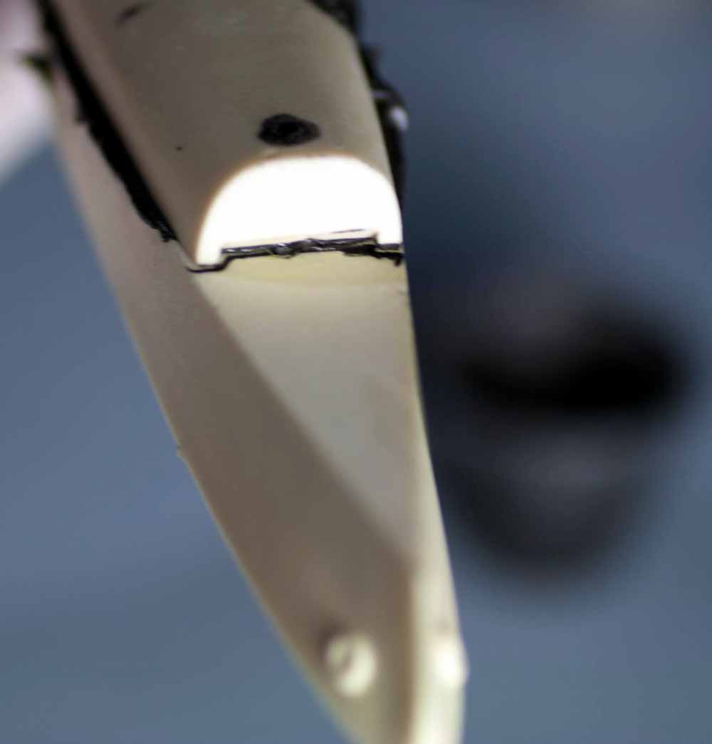
Fig.32 The screws are as torqued as they’re going to get and the epoxy has finally stopped oozing in large amounts. As you can see the hull is a mess right now but the gross cleanup is done. Throw away the messy napkin and change your messy glove now.
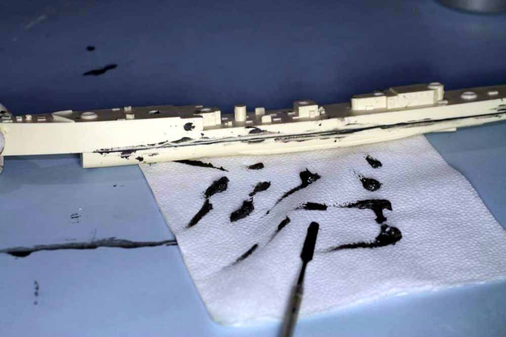
Fig.33 With the new clean glove on your hand, handle the hull by areas that do not have epoxy on them. Using q-tips wet with acetone scrub the excess epoxy off the hull. Make sure to get every little speck of it off and check to make sure you didn’t leave a finger print of it from your first messy glove somewhere on top. You may find small amounts of epoxy still oozing out of the seam, use the spatula to scrape them off and go back to acetone and q-tips. Finally take a piece of napkin wet with acetone and wipe down the entire hull. The goal is to only have epoxy visible along the seam and in this case where the holes are drilled through the lower hull. You want the epoxy in both areas to be slightly concave, you do not want to try sanding it off after it’s cured. Keep checking the seam for squeeze out for about 45 minutes. At this point set the hull aside overnight for the epoxy to fully cure. The total labor time from opening the box until now is one hour and forty-five minutes, we have not made a huge mess with resin dust and we have not used finicky clamps.
Fig.34-39 Various views of properly cleaned epoxy. Make sure to check for ooze around screw heads.
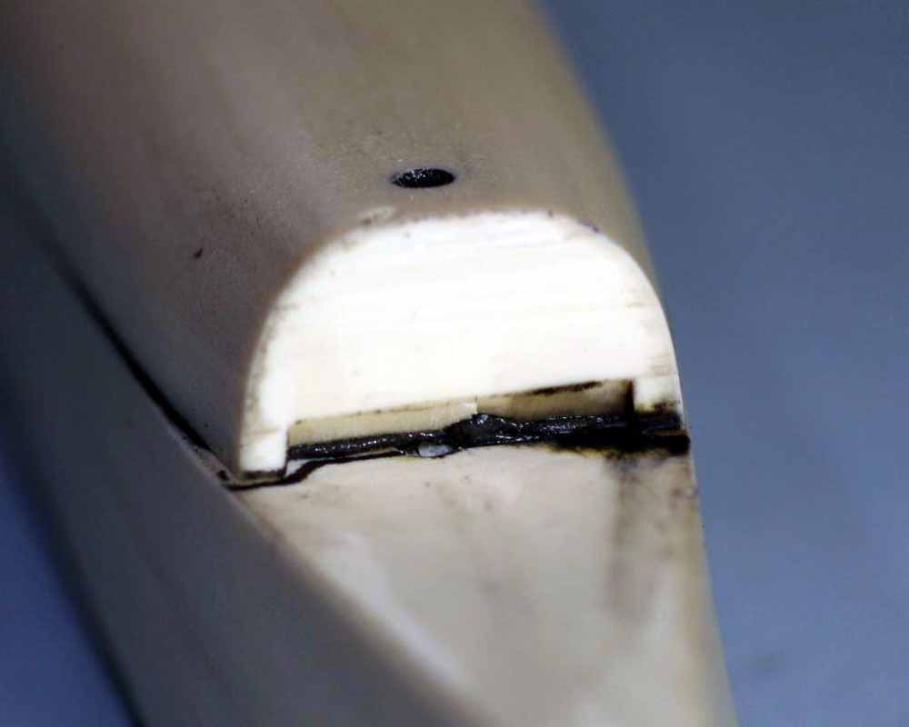
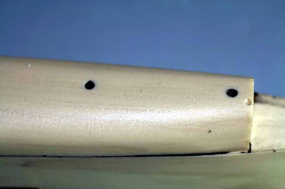
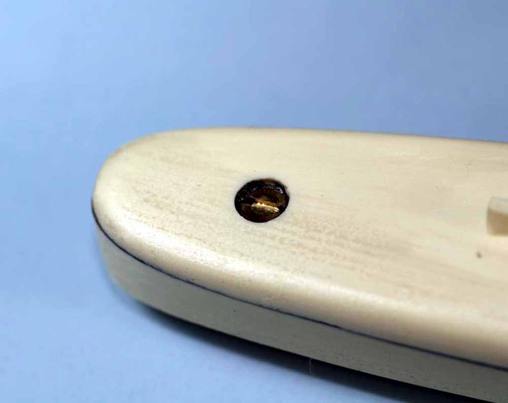
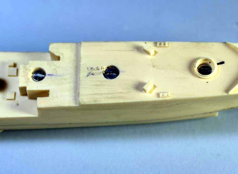
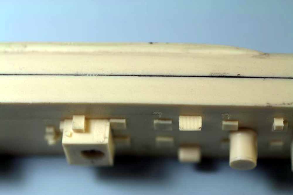
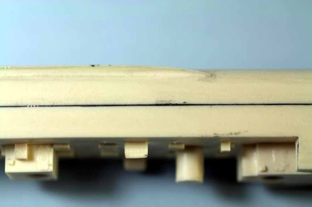
Fig.40 Using a slow setting, thick CA such as the Slo-Zap shown, it is now time to glue the bow piece in place. Spread a film on the bow piece itself, set in place, line up and hit the seam with accelerator. As soon as you’re sure the CA has set sand off any that has oozed out on the hull, if you wait too long the CA will be harder than the resin.
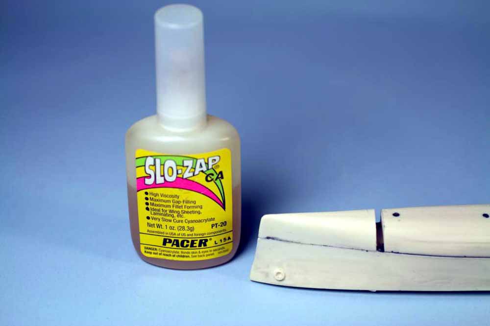
Fig.41 Next use clear packing tape to mask the area around the gap, press it down tight and burnish it. Make sure the tape is pressed tightly into any slight step along the seam, the resin we’re going to use to fill the gap will seep into the smallest crevices. Cut a small hole in the tape at the center so you can use a disposable pipette to inject the resin.
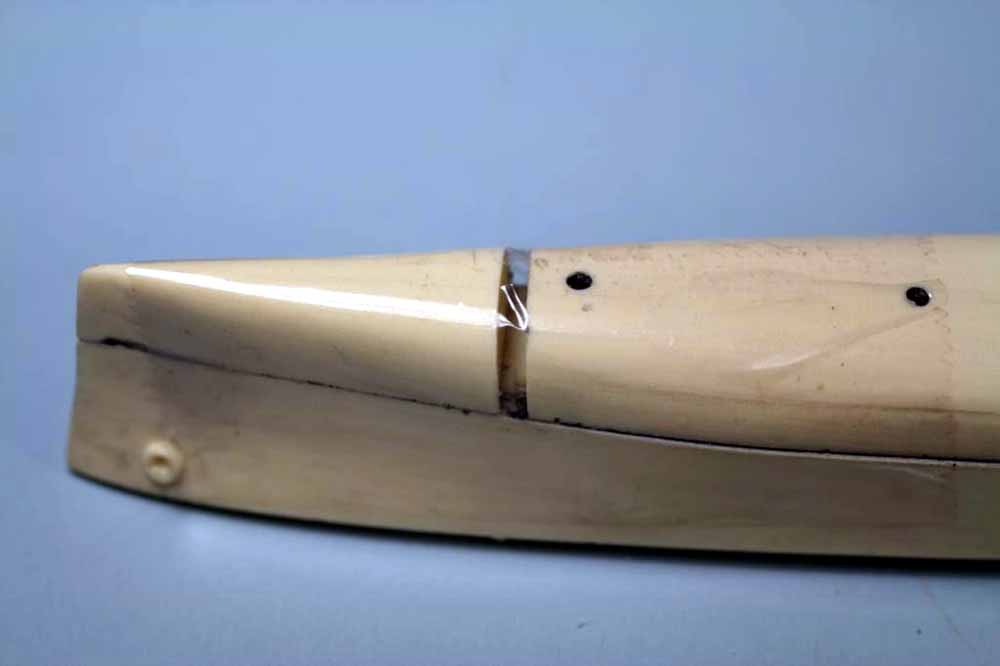
Fig.42 The first photo shows the tip of the pipette in the hole and the resin being injected, the small amount that has leaked around the hole shows why you want to mask a large area around the gap. The second photo is the resin filled gap. Don’t worry about the little concavity where the hole in the tape is, once the resin is cured we’ll fill that when we putty the hull.
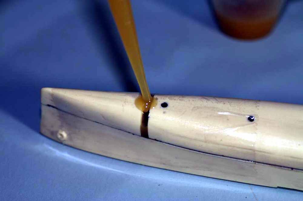
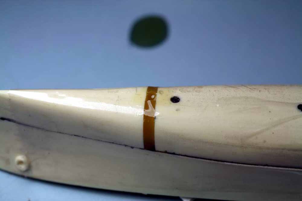
Fig.43 Now that the resin has cured the tape has been removed and I’ve combined several simple steps. This photo shows the entire hull bottom with a centerline marked, holes for pedestals drilled and tapped and minor defects marked in red to pay attention to when the hull is puttied and sanded. I find the best location for pedestals is one third the total length of the hull from each end, it just looks balanced. Since I use lamp shade risers the correct thread to tap is ¼”-28, most hardware stores carry a tap and tap drill set in this size. Do not try to drill the full sized hole in one shot, start with something like a .040” bit, then step up to 1/8” and finally the full size bit.
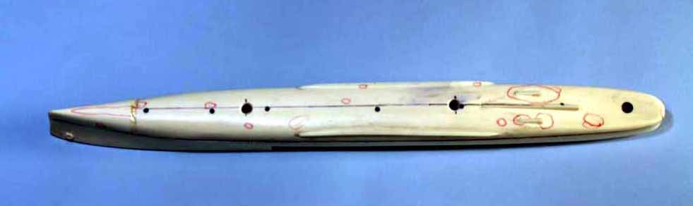
Fig.44 This is a closeup of the forward pedestal hole, notice the edge has a slight chamfer from a countersink, it makes things a little neater. The hole looks off center but it isn’t, the centerline was off to one side about a millimeter so I shifted the first drill bit off the line just enough to truly center the hole. Always sight down the hull when you first place the bit to make sure it’s centered. The two left red circles show minor concavities in the hull that will need to be puttied and the right red circle shows a small bit of excess resin that will need to be sanded off. I find marking these kinds of minor defects helps me when it comes time to apply putty and sand.
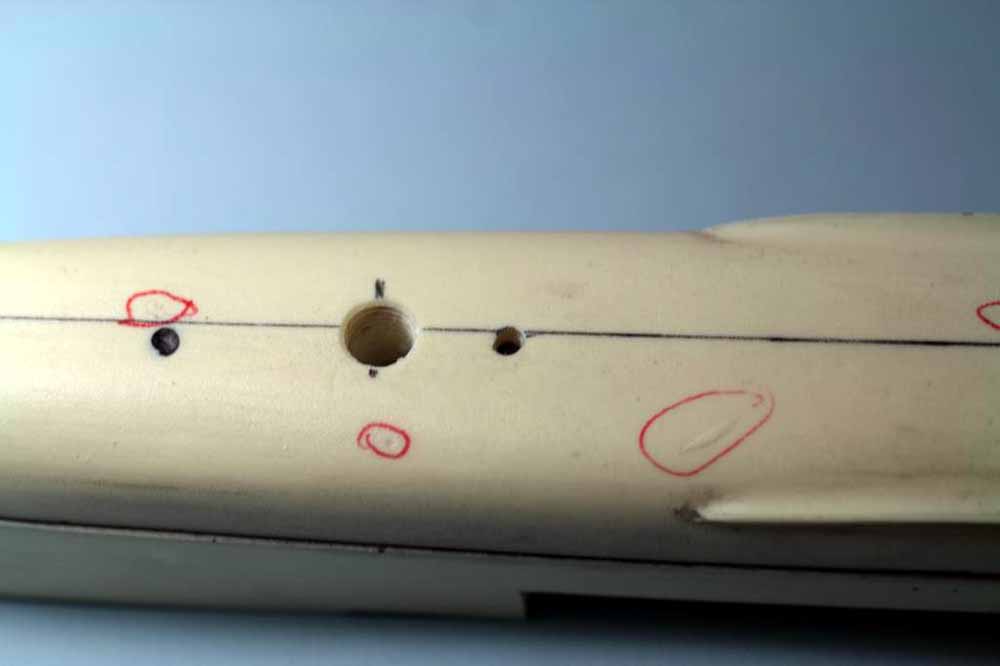
Fig.45 The lamp shade risers temporarily screwed into place just to show you what they look like. Most hardware stores carry at least one style of them and they make nice quick display pedestals. Stores that specialize in lighting and lamps generally have at least a dozen styles to choose from, some of which are more appropriate to larger ships. At this point I make a wooden base for the model, I prefer a fine grained hardwood such as cherry or curly maple but you can use whatever pleases you. If I’m not going to have an acrylic case made I size the base 1”-2” longer than the model at each end and ¾”-1” wider than the widest part of the hull one each side. The smaller dimension is for destroyers and light cruisers, I allow a little more for larger ships like heavy cruisers, battleships and carriers. The details of making the base are beyond the scope of this article.
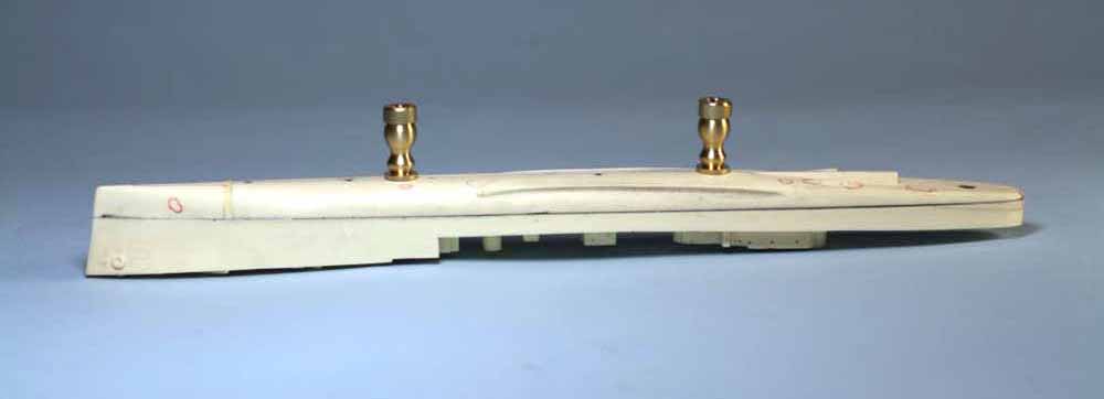
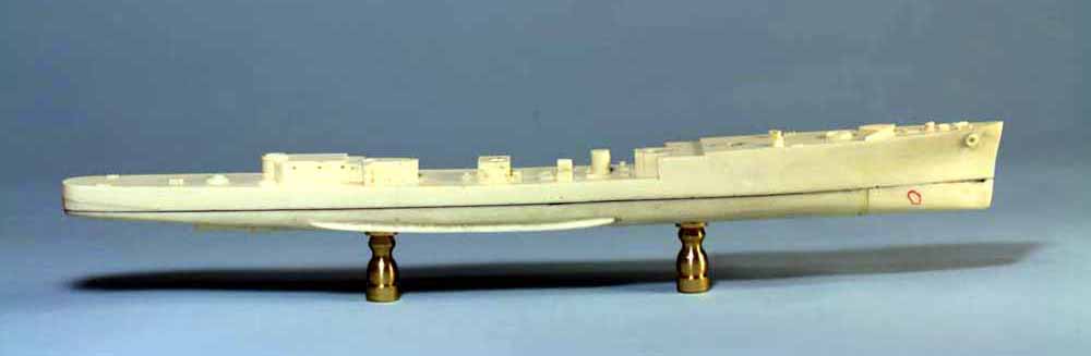
Fig.46 The Somers class as built had portholes in the hull, the kit does not. The hardest part of drilling portholes is lining them up so they don’t look snaggle toothed, followed by accurately spacing them. Another “magic” tool is the screw adjustable compass, it can be used for more than just drawing circles. Luckily I have plans on CD for the class and it was a relatively simple matter to redraw and rescale in a CAD program to produce a print I could work from simply by setting the compass on the print. The portholes on this class of ships follow the deck line, which follows the sheer, both fore and aft. Photo B shows the compass set to the dimension from the deck surface to the centerline of the portholes, make sure to compensate for the shaft of the point which will ride the deck edge. Allowing the shaft of the point to slide along the deck edge and making sure to hold the compass firmly so it stays perpendicular to the edge just follow the sheer and mark the line. Photo C shows the forward portholes marked out, I have already pilot drilled the upper row with a .020” bit in a pinvise. The trick is to find one porthole you can accurately index from some fixed point on the hull and set the compass to that dimension, place the compass point on your index and swing the compass in a small arc that crosses the appropriate line, that’s your first porthole center. Select the next porthole on the drawing and set the compass, press the compass point into the resin where the first tick mark is, swing in a small arc across the index line to mark the next porthole, repeat. I find it helpful to mark the portholes on the drawing as I mark them on the hull. By pressing the compass point into the resin, you provide an accurately placed pinprick to center your pilot drill. As always, never try to drill a hole that must be accurately located in one shot, always use a smaller pilot drill first. Do not drill anything until all the portholes in the area are marked out. Note that gaps in the index line are where a deck fitting interferes with the compass point while tracing the lines. For these photos I inked the index lines as they are faint but in normal practice I just use the pencil line. For the historically curious my compasses were my grandfathers when he was chief draftsman at Camp Springs Army Airforce Base in WWII, it is now Andrews AFB.
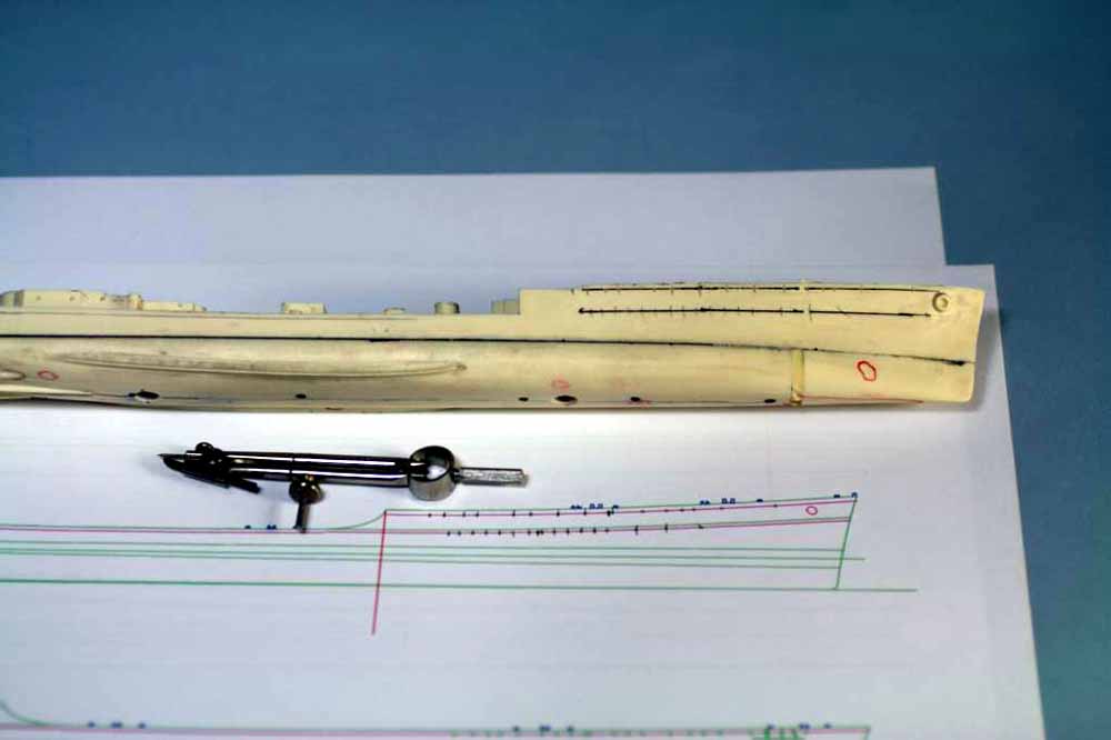
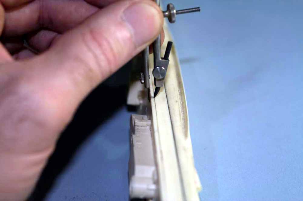
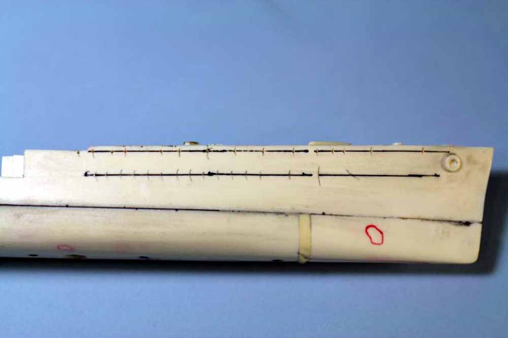
Fig.47 Putty time! Ok, everyone hates putty work but I find it’s easy with high quality putties. I prefer to use a polyester putty for the initial coat and large fills. It is a two part putty that has a small range of variance allowable when mixing catalyst into it for altering the cure time (be careful and don’t get too happy or it will set too fast or never set at all). Be warned, this stuff STINKS! My preferred putty is Evercoat Glaze Coat available at professional autobody supply houses but Tamiya polyester putty works just as well if you don’t want to buy a quart. Mix per the directions and apply with a stainless steel spatula, only mix what you can use in five minutes or it will start to get unworkable. It is sandable within 20-30 minutes but I prefer to wait a full hour. As you can see I’m not real neat with the first putty application, for 3-8 hours this stuff is a bit softer than the resin so you can sand until you hit resin without doing more than scratching the resin. I use a coarse (220 grit) sanding stick or paper wrapped around a block and wet sand. Sand back to the resin surface being careful not to hollow out areas of putty where you need a little build up for contouring. This sanding is best done at a sink with the water running. One advantage to polyester putties is that you can change catalyst colors for multiple coats so you can see each layer as you work.
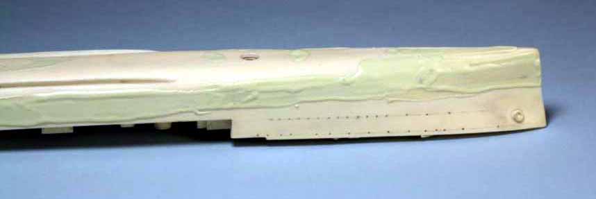
Fig.48 The rough sanded hull, notice the areas along the seam where there appears to be a large patch of putty. Those areas are where I needed to do a little contour building because of a minor step in the parts, it’s not as bad as it looks though since there is at most .010” step. There are some minor scratches from the coarse sanding stick but the next putty application and sanding will fix that easily.
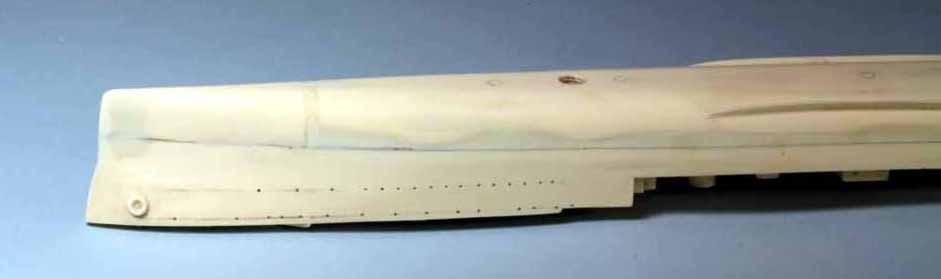
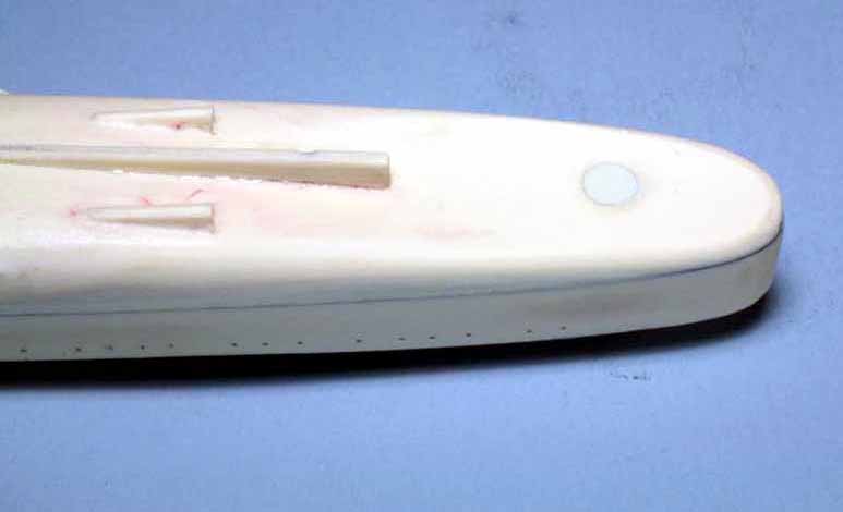
Fig.49 Here is where truly good putty pays for itself, I use Spies-Hecker Permacron 7715 which is a solvent based putty like the Squadron green and white putties. Again it is a professional autobody putty, it spreads very thinly with a spatula, sticks to both plastic and resin and can be sanded within 30 minutes when used as a glaze coat on resin. Photo A shows both the as applied putty (average film thickness .005” not including the few blobs) and the first pass with a 400 grit sanding stick. Wet sand and take your time, knock the worst off then come back with a 400 or 600 grit stick or paper and give the entire hull a quick, light wet sanding. Notice in both photos how the putty stays in the scratch marks, that’s what this particular putty is meant to do. Photo B shows the stern after the final sanding, the larger dark yellow patches of putty are over minor surface imperfections but the maximum thickness of putty in this photo is .002”. The faint red stains are from the marks I used to indicate where I needed putty.
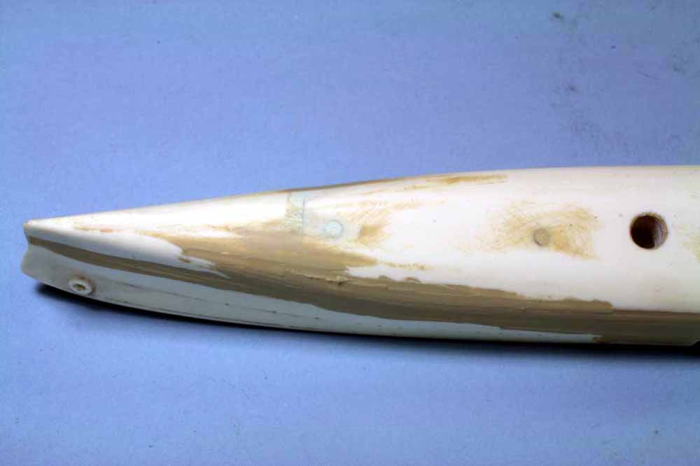
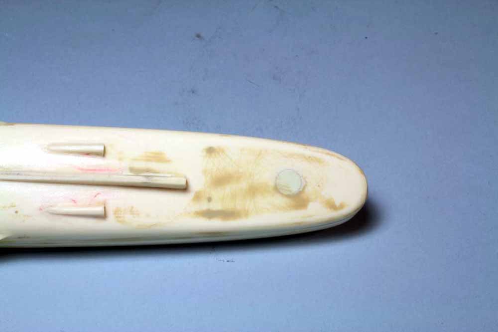
Fig.50 Now we start to prep some other parts that will be glued to the hull before priming. This is the forward deck house having its pour plug removed with a JLC razor blade saw. I like this particular saw because it leaves a very thin kerf, is stiff and very sharp. As with the hull start the cut by laying the blade against the bottom of the part and cut a shallow kerf into the pour plug, work around the entire part. The shallow kerf will help guide the blade as you get more aggressive and work to cut the pour plug away. Once the plug is cut off use 220 wet/dry paper on a piece of glass to dress the bottom of the part flat. If you cut the plug free correctly it should take no more than two or three swipes to flatten the bottom. Set the part side for now.
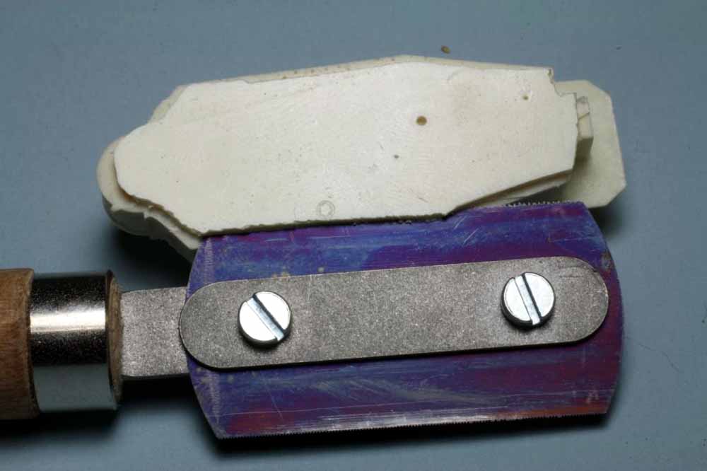
Fig.51 Some deck parts are cast so the pour plug hangs off the underside of one end, this can be difficult to remove. Using a fine razor saw I first make a stop cut into the block that’s a little deeper than the part is thick along the edge of the part (photo A). Then I use the part itself to help guide the saw as I cut down into the pour plug (photo B). When you hit the stop cut, the part will pop free. Photo C shows a different part which has been flipped to show the backside and the slight bit of resin to file off.
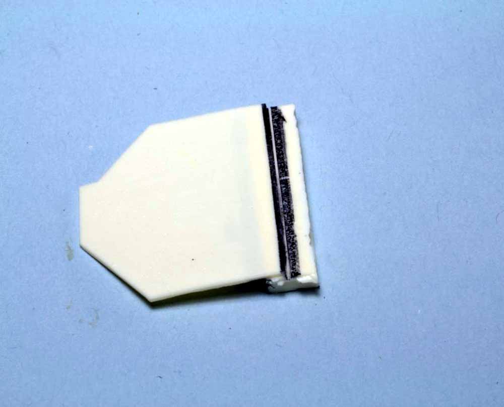
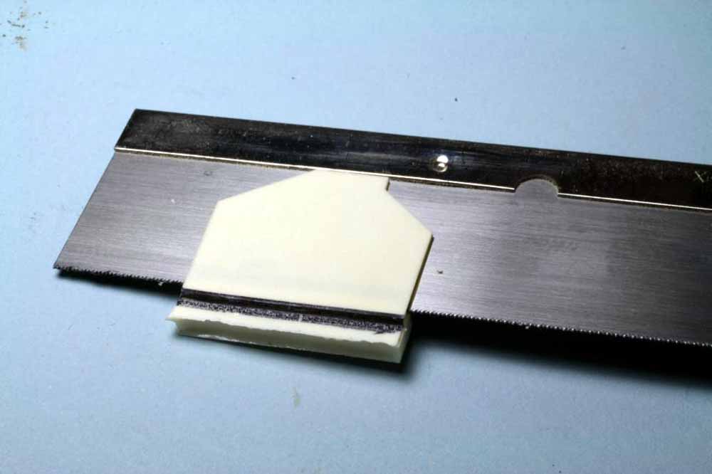
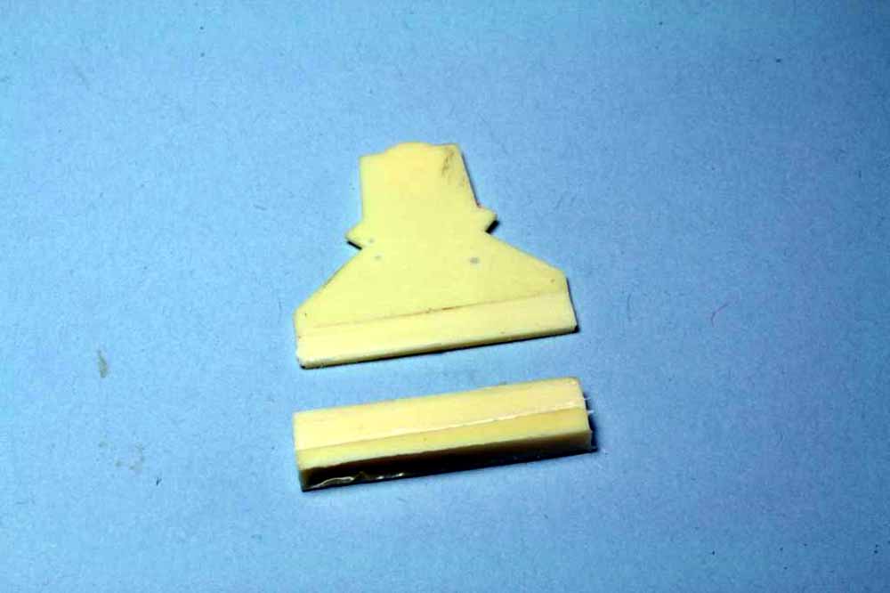
Fig.52 The most used file on my workbench is a 10” plastic laminate file. It has a coarse side and a fine side, which is up in the photos. This type of file is made specifically for plastic, do not use it on anything else. It cuts fast and the fine side leaves a surface better than 800 grit paper if you do your part. The surface it leaves is so good I have shot gloss sea blue on a recontoured aircraft tail with no further prepaint prep. If you need a truly flat surface or sharp corner a file is the best tool to use. Like any file do not scrub back and forth on a part, files only cut on the forward stroke. When working on parts like this I prefer to lay the file on the bench and drag the part towards the handle, it gives me better control on small parts. A few strokes on the file and this part will be ready to glue in place.
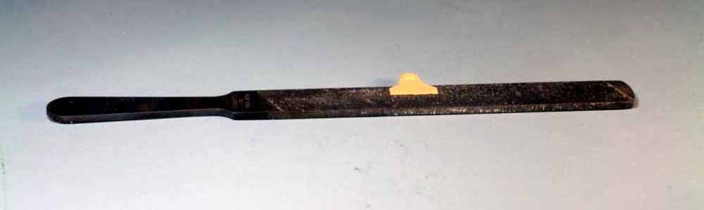
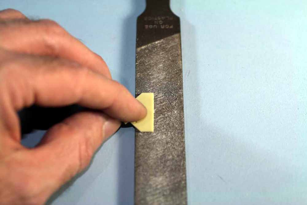
Fig.53 Now we’re ready for our first white metal parts. These are a non-lead, soft alloy that almost always have bit of sprue, flash and mold seams to clean up. Just use a decent pair of diagonal cutters to snip off any sprue close to the part. Flash can be trimmed with a scalpel or X-acto knife. Mold seams are best dealt with using a needle file and/or sanding stick. White metal parts are filed/sanded just like plastic, it just takes a little longer. The material is a bit “gummy” and tends to load files and sanding sticks quickly, so I find it best to dedicate a needle file and fine sanding stick to just white metal. In the photo the rudder is prepped and ready to mount as are one each prop shaft and V-strut. Compare the prepped parts to the unprepped parts next to them
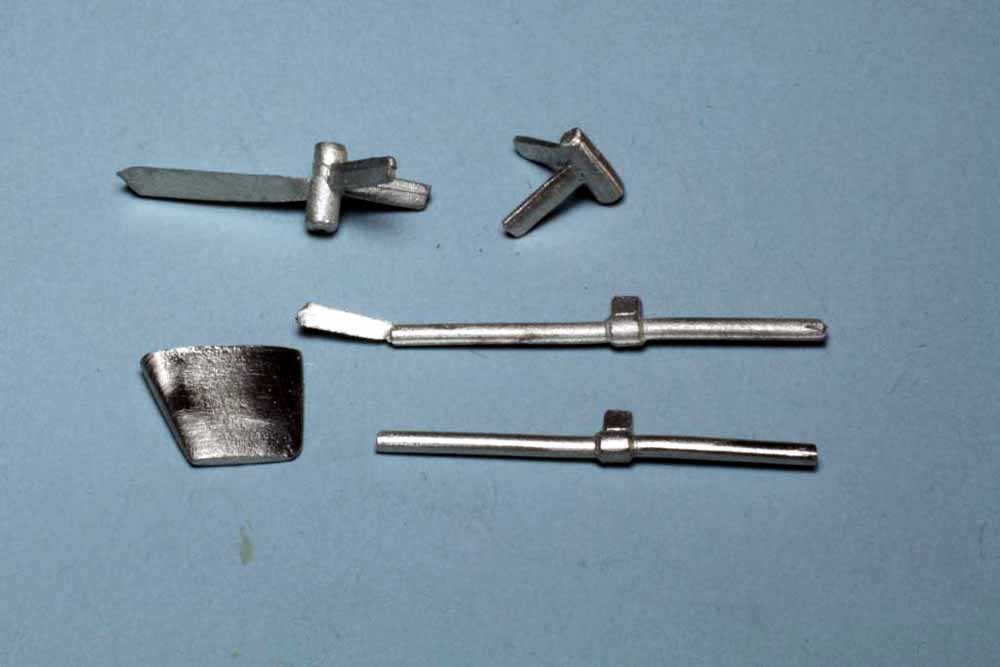
Fig.54 I have added two deck parts that will have an exposed seam and thus need filling and sanding before painting Also visible are a few minor dents in the deck surface that have been filled and sanded. The deck parts were glued on with CA, use a very small dot of medium CA where the part will mount, place the part and you’ll have a few seconds to align it properly. Once aligned add some thin CA using the end of a wire or needle around the edges of the part, putty and sand smooth. I waited until after sanding to ream the portholes to the final size. I used a .040” bit since that’s the size of the portholes in the superstructure.
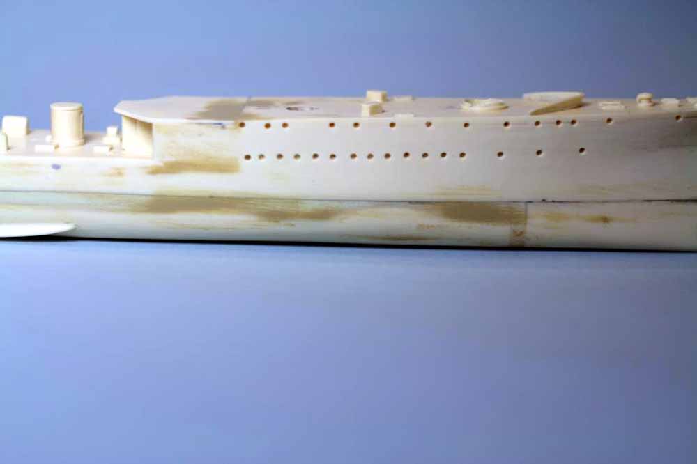
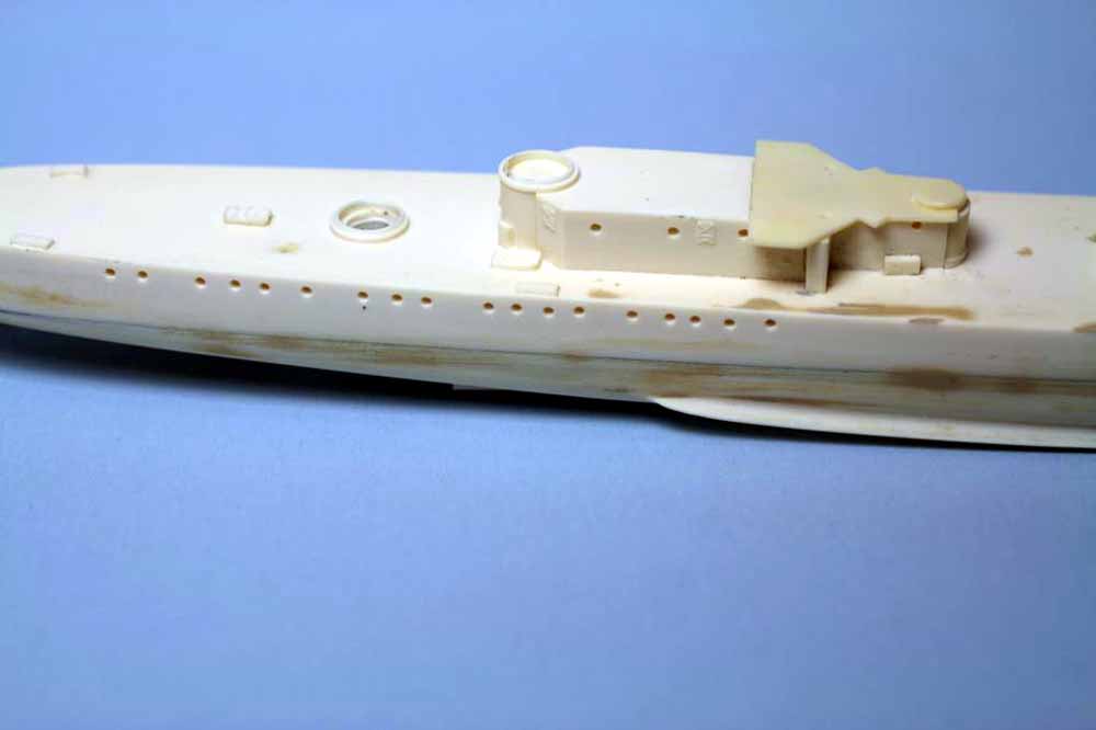
Fig.55 The forward deckhouse needed a bit of work before gluing in place. There were a few minor surface imperfections, two portholes out of line and three with resin in them. The latter three have a little ink smeared over them to help them pop out a little. A bit of excess resin or slightly out of round portholes are fairly common on resin kits, just ream them out with a drill bit and pinvise. The two misaligned one have been puttied and sanded and just need to be drilled out. Notice that portholes in the watertight doors are a bit smaller than the ones in the bulkheads.
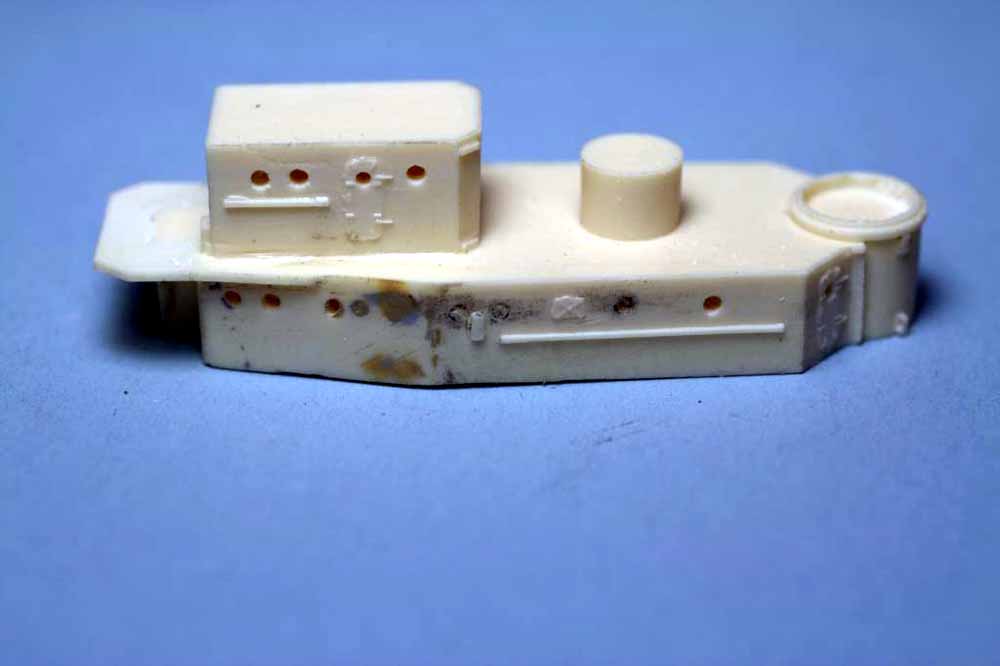
Fig.56 The kit instructions and USN plans for the Somers class show two companionways cut into the deck at this level. There are no thinned areas or marks to locate them, I marked them out with the screw compass being careful to avoid overlapping the structure underneath the deck. Mark the width just under that of an inclined ladder. Then use a small bit in a pinvise to drill a series of holes just inside the marks, slip the point of a #11 scalpel into a hole and gently slice from hole to hole. Once the little chunk of resin drops free use needle files to true up the ends and inner edge of the hole. File the outer edge and stop when an inclined ladder freely slips into the hole. This is much easier to do before you mount the part to the hull.
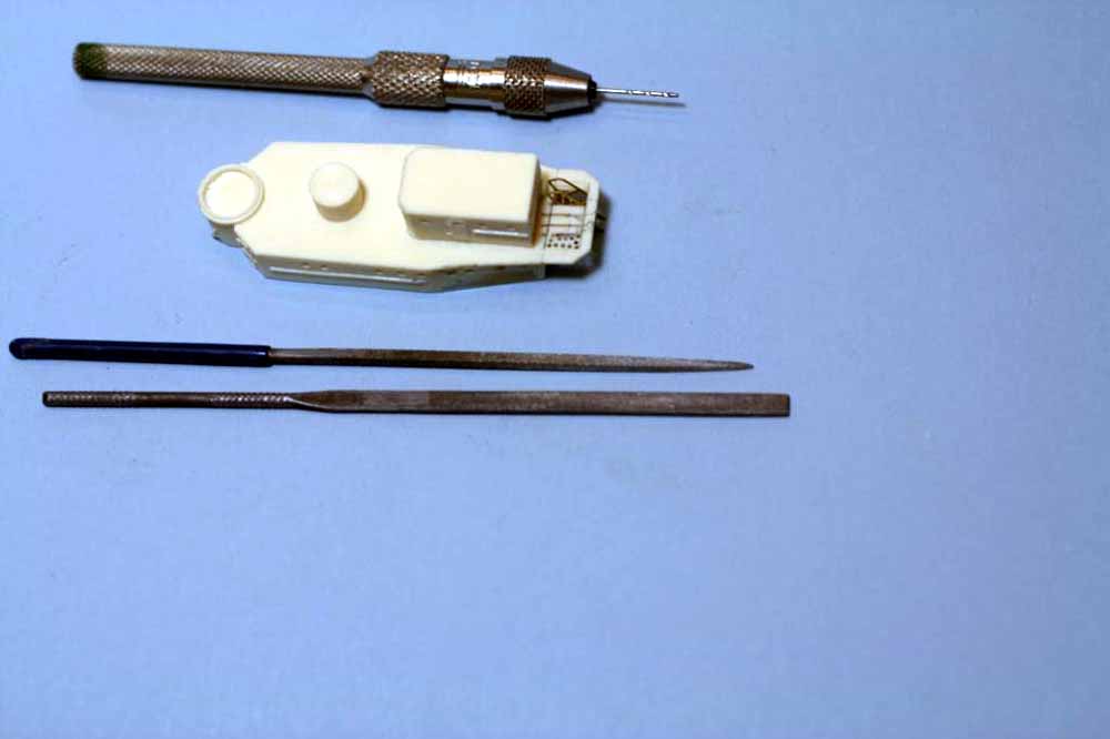
Fig.57 The forward deckhouse glued in place along with the 1.1” gun platform. The small gap visible has been filled with white glue. Just take a piece of wire, dip it into a puddle of white glue and apply to the gap, let it sit a minute or two and use a damp q-tip to swipe off any excess. White glue does shrink when it dries so you may need a second application.
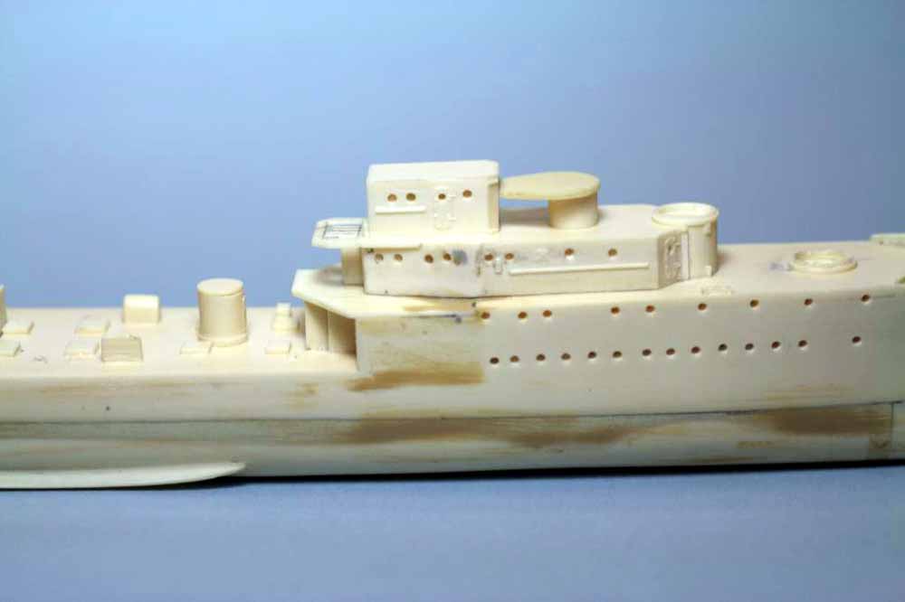
Fig.58 I have added a small styrene triangle to the keel extension to match drawings and photos of the ship, just CA it in place and file/sand to fair it in. The kit prop shafts placed the props too far forward so I drilled out the V-strut housings and the mid-shaft support to accept a .047” diameter piece of styrene rod. Slip the mid-shaft support on the rod and slip the rod into the V-strut then into the outlet fairing on the hull, trim the styrene rod to length until the V-strut sits in the correct location. Next check where the mid-shaft support should be and slide it to there, chances are you’ll need to trim the “leg” a bit for it to fit. On the Somers class the mid-shaft support angled in toward the keel at the hull as you can see in the photo so keep that in mind while trimming the “leg”. Use CA to attach white metal parts, I glue the shaft to the hull first, then the V-strut to the hull, lastly glue the mid-shaft support. Use a little CA to fair the mid-shaft support and V-struts to the hull and sand lightly. Always check your alignment before applying glue and check it after each application to make sure parts didn’t shift. If you do it right no glue will be needed where the shaft passes through the mid-shaft support or the shaft/V-strut joint. To ensure a solid mount for the rudder I glued two pieces of .020” brass rod into the rudder and then marked the hole locations on the hull and drilled them, I’ll glue the rudder in place just before shooting primer.
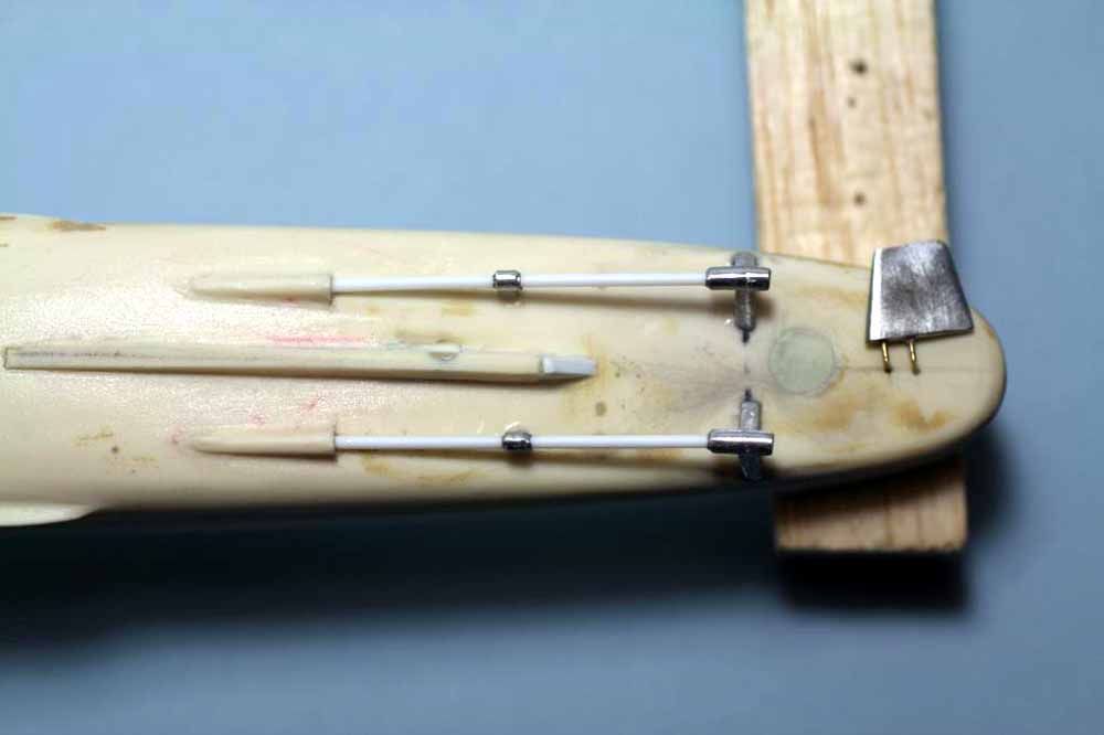
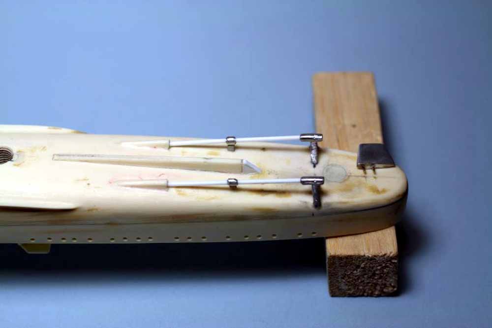
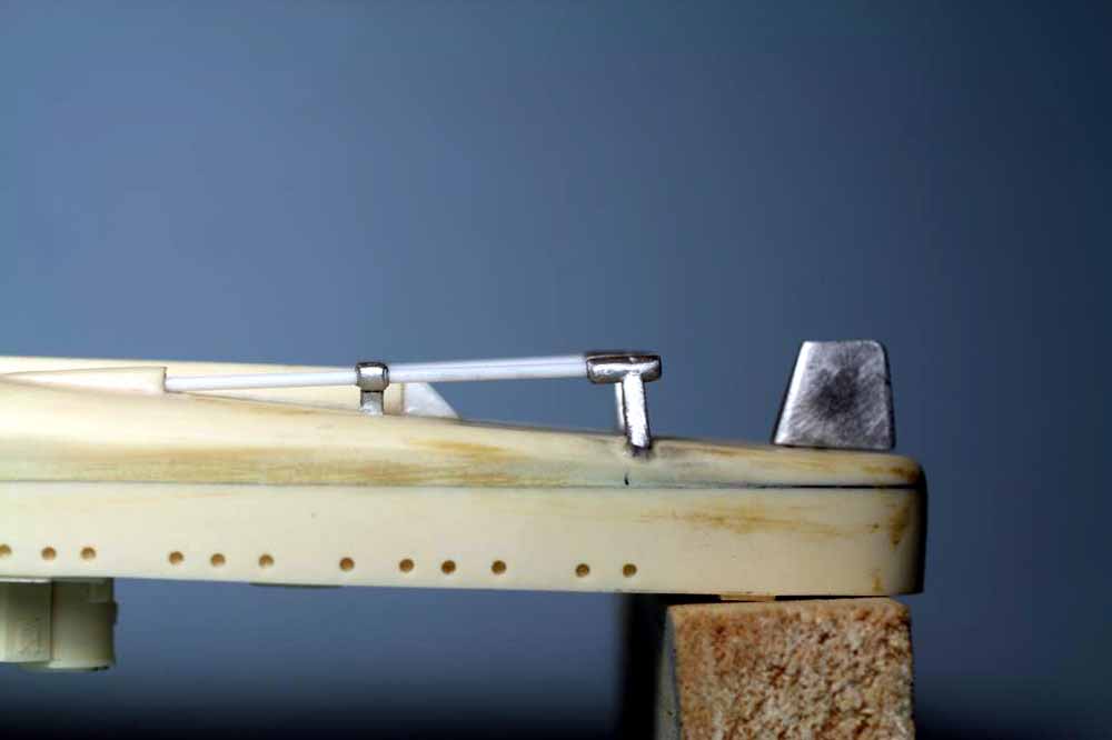
Fig.59 This is one the few resin kits I’ve built that doesn’t have cast in bitts which usually break off. The kit instead has bases for the bitts cast in place. The four bases for 18” bitts forward of the forecastle break are fine as is, just drill them out to accept .040” diameter styrene rod, CA the rod in place and cut flush using a .060” high spacer. The reason I use styrene rod here is that .040” and larger sizes tend to be truly round and brass rod that heavy can damage the flush cutters. The four aft bitt bases are a little off, they are for 10” bitts and there should be six bitts aft of the forecastle break. The aft most pair are located properly but like the pair a bit farther forward they have a larger footprint than the 18” bitt bases. So I shaved them off and using my plans located where the six bitts should go. I used a Chopper to cut some strip styrene, .015”x.080” stock, to a length that looked right. Pick up the pieces with the tip of a sharp needle and apply a tiny drop of CA to the underside and place on the deck, make sure to leave a little room at the outer edge for the railings later. Drill two holes in each to accept a piece of .033” diameter brass rod, CA the rod in place. Cut to length with a small jig laid against the bit as shown, I used .015” and .040” styrene laminated. Once all the bitts are cut flush, lightly sand the tops to just remove the cut marks.
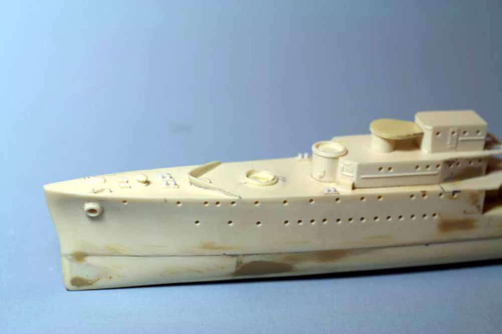
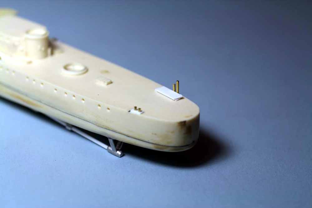
Fig.60 Like most resin kits you’ll need to dig up your own anchor chain and drill out the hawse pipes. I like to start with the hull side and drill a little deeper while reaming the hole up to correct size to allow the anchor stock to enter realistically. For the deck hawse pipes I first select a chain of proper size (I’ll be using 42lpi from Tiger Model Designs on this ship) and then using several drills in a pinvise to drill and ream the hawse pipe to a size large enough to just accept the chain and deep enough that at least one link disappears inside the hole. US DD’s only had one capstan so only one chain routes around it before entering the chain locker, the other chain is stoppered and runs into the chain locker. The two cylindrical items forward of the capstan represent the pivoting chain locker entries as used on US DD’s. Drill the aft end of one to accept the chain and the forward end of the other. Be very careful as you’ve only got about .005” wobble room for the drill bits.
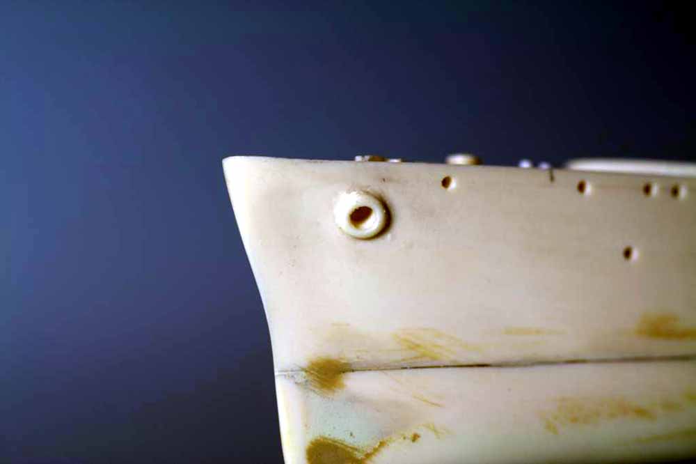
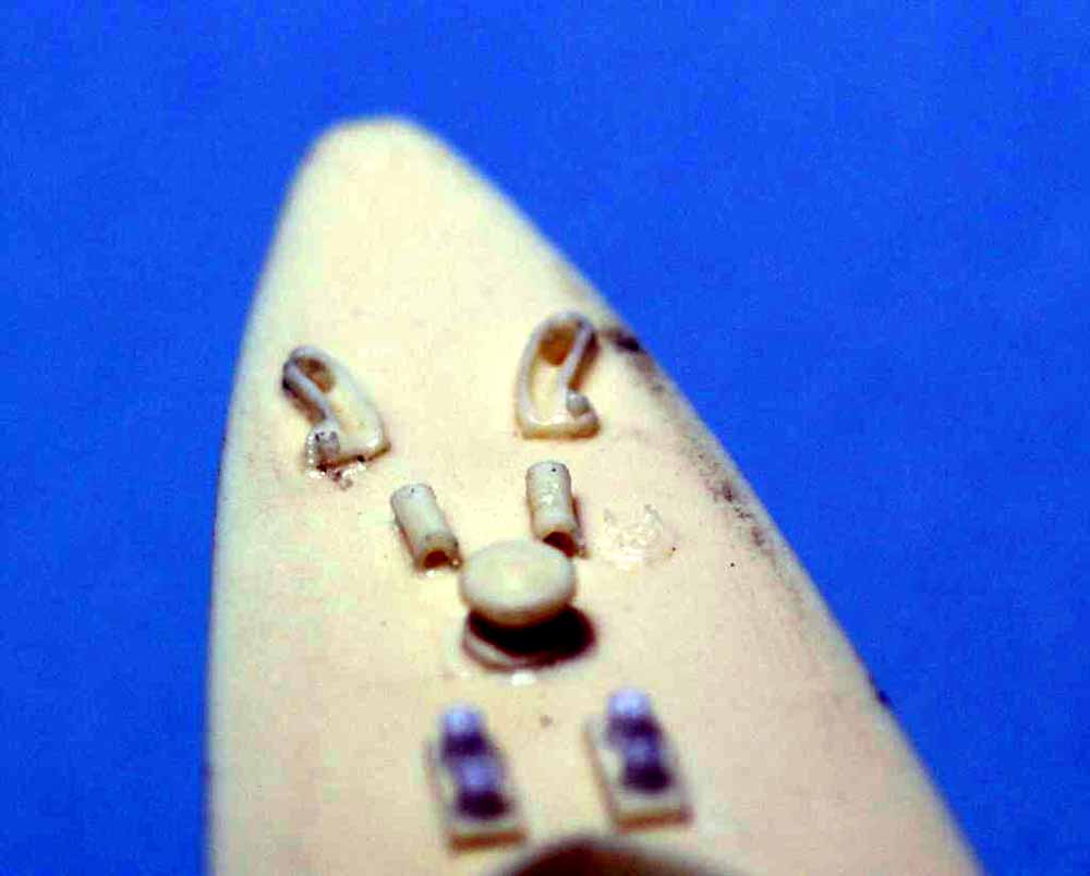
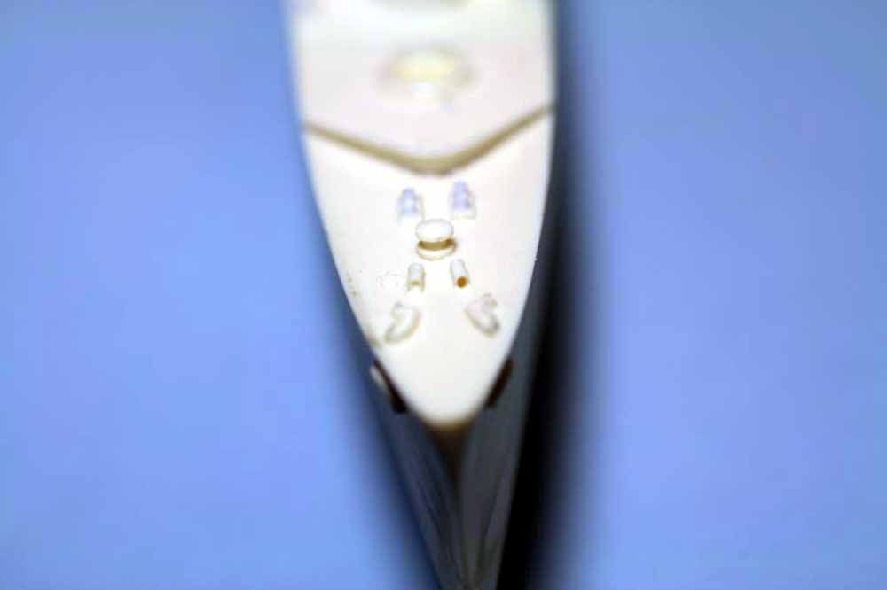
Fig.61 Final delicate hull details are the chocks and prop guards. I have used a spare set of white metal chocks from an old Classic Warships light cruiser and made an RTV mold then cast them in resin. They have been sanded thinner and slightly shorter to better fit a destroyer. Simply repeat the compass trick to locate one edge of the chock and CA them in place. Chocks should be flush to the edge of the hull. Next mark the location of the prop guards using the compass to locate the parts and a ruler for the straight lines. Then use various bits of styrene strip to build the prop guards, I make a quick and dirty jig from aluminum strip bent to shape and tack the horizontal member of the prop guard to it with a dab of CA at the ends. I deliberately make the styrene strips too long, then dip into boiling water for 20 seconds to set the shape of the strips. Once cool cut to length at the correct angles and CA to the hull. Add the verticals and you’re good to go. Now glue the rudder in place and set the hull aside for priming. Just so you know, even with little details like correcting the bitts and adding portholes the total labor time for the parts you’ve seen is only about 4.5 hours.
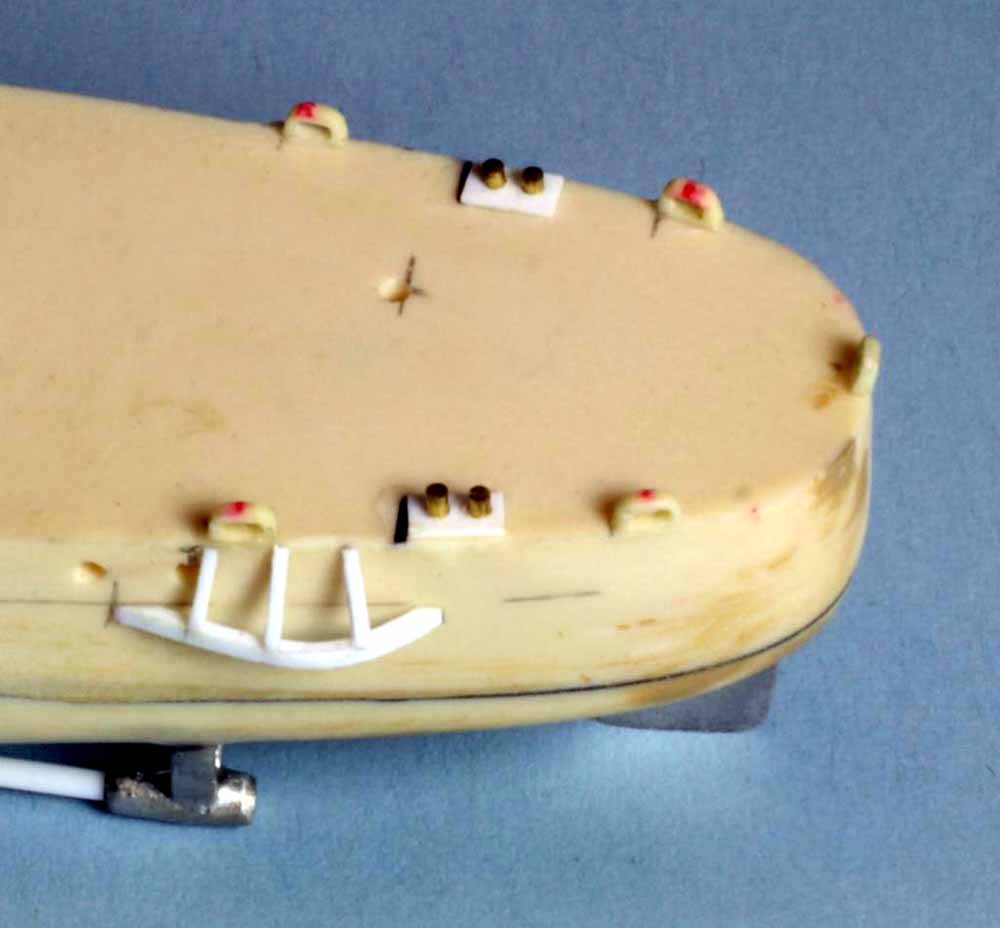
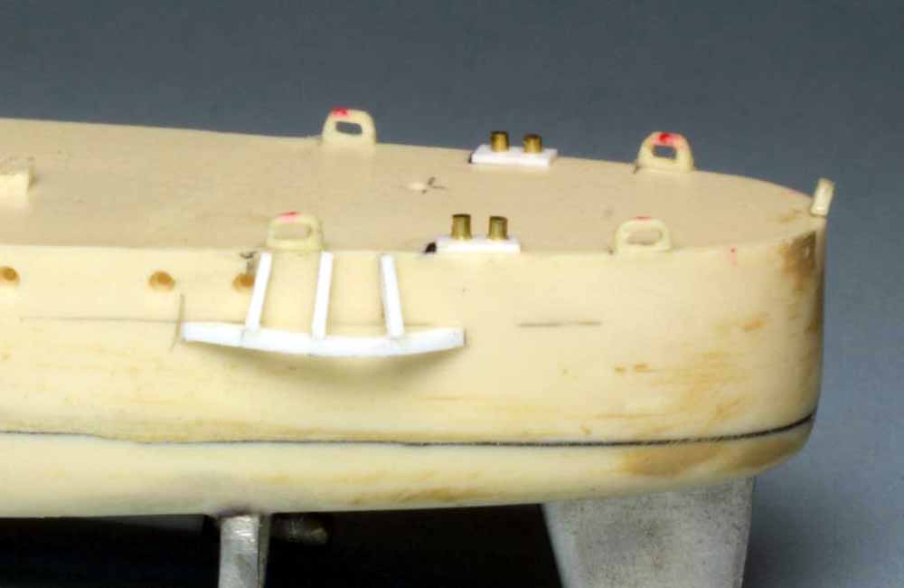
Fig.62 An alternate method to razor sawing the pour plug off is to use a regular drill bit, turned by hand, to hog out the middle of the plug. It cuts down a little on the sawing and the slight hollows in the base of the part allow it to be dressed flat a little faster. As long as the hollows are not too close to the edge they will not affect gluing the part in place.
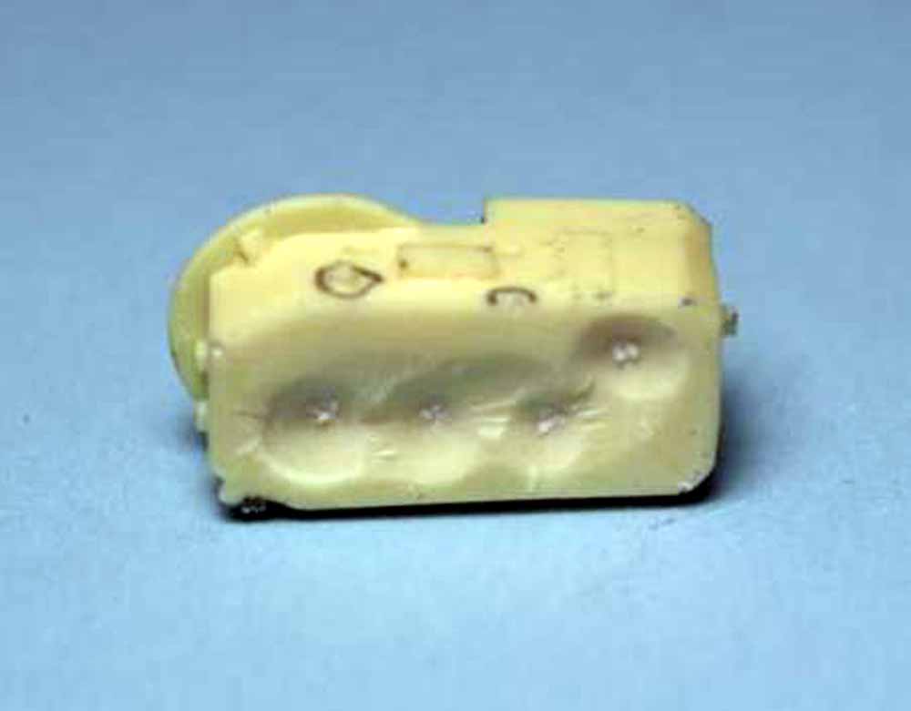
Fig.63 A few of those little bubbles I mentioned as typical resin kit defects. They are caused by tiny air bubbles trapped in the resin during molding. On better kits they are small and very few in number, in fact these two parts and the stack uptake are the only parts in this kit with this defect. I have circled them with a black Sharpie.
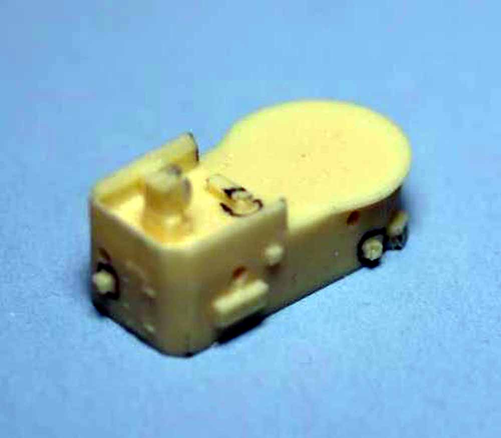
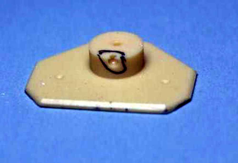
Fig.64 The fix is an easy one. Using a drill in a pinvise that’s the same size or a tiny bit bigger than the bubble, drill it out just enough to slide a piece of styrene rod into it. Dip the end of the rod in CA, slide into the hole and snip off so a little protrudes. Once the CA has cured go back with a #11 scalpel and slice close to the surface, if you’re good you can slice right to the surface and you’re done. For the larger rod on the bridge roof I sliced close and used a sanding stick to finish it off. Once primed and painted you’ll never know those bubbles were there.
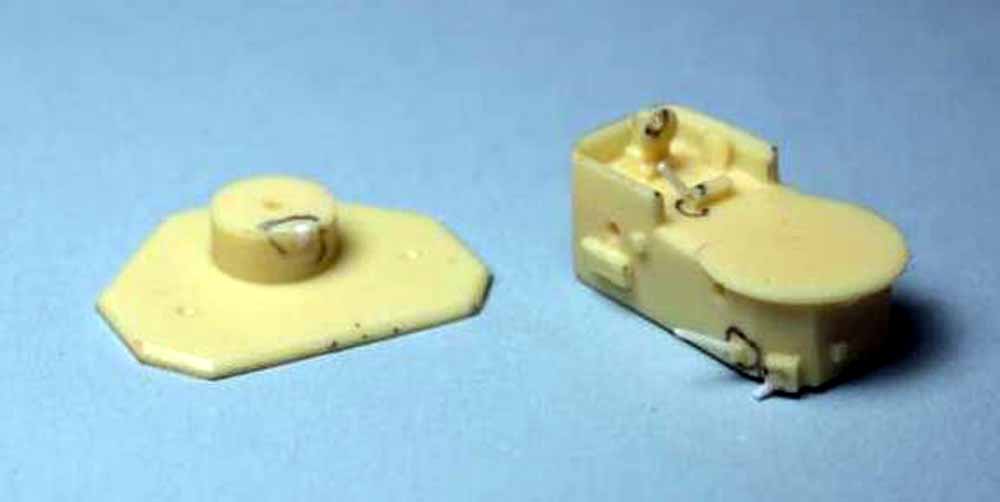
Fig.65 Now we’ll move on to another defect fix and starting subassemblies. In this case the defect is twofold, I broke the part while removing the pour plug and the “wings” have a slight downwards warp. If this was a more massive or difficult to replicate part I’d use either boiling water or a heat soak in the oven to fix it. Since it is just a .030” thick deck piece I made a new one from styrene stock. My kit had both white metal and resin stack uptakes, the resin was cleaner and a much better fit so I’m using that one. The red putty is where there were a few minor bubbles and this part is a simple enough shape to use putty then sand smooth. The square hole in the broken deck piece sits over a square boss on the uptake, using the original part for dimensions I selected bits of strip and sheet stock to build the new deck piece in place on the uptake. Use the raised boss to locate the parts, when you glue the largest part in place have the uptake tacked in place with white glue on the hull so you get the deck piece level with the deck house the aft end sits on and centered along the hull. I started with the largest part first, once the CA for it was cured I dismounted the uptake from the hull (cleaning off the white glue from both parts) then added the forward most piece of styrene. It’s a simple matter to then select some strip and fill in the gaps along the sides. Two minutes with a tool similar to “The Chopper” and the wings were cut to shape then CA’ed in place. Be careful not to get too much CA under the deck parts as it is very difficult to file or sand down there and it is visible. A little excess CA up top won’t hurt since you can easily file or sand it back. Photos show the deck around the stack to be flush with the rest of the decking in that area and the raised boss on the uptake isn’t quite high enough so a little putty and sanding is called for. I’ll add the torpedo base when I add the stack.
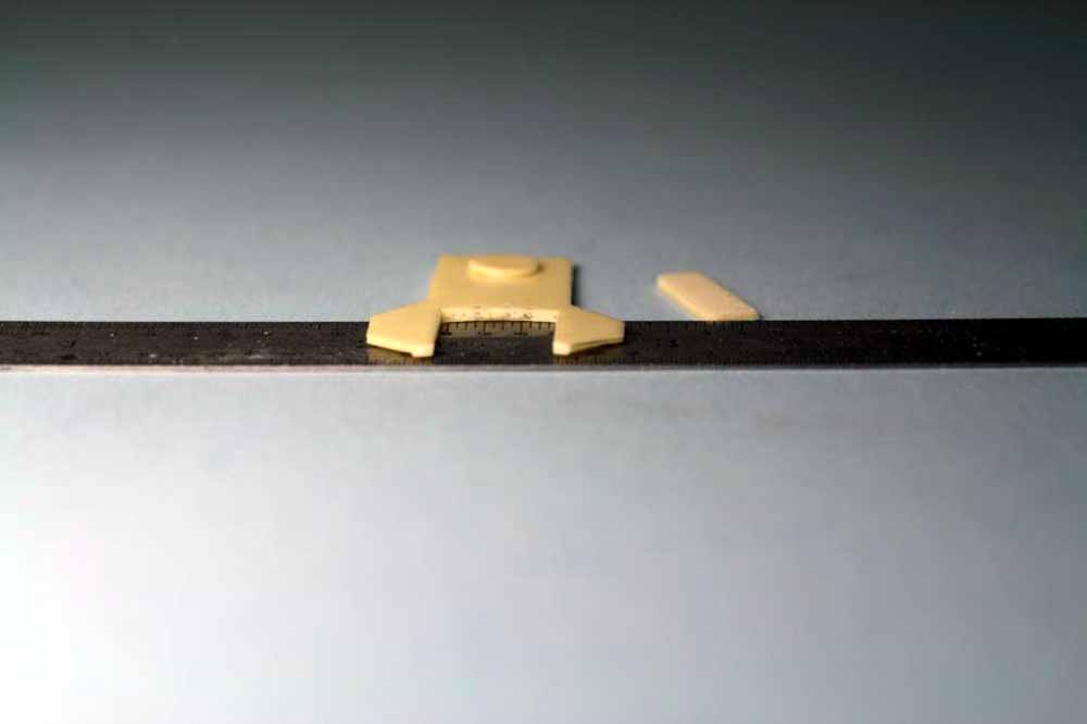
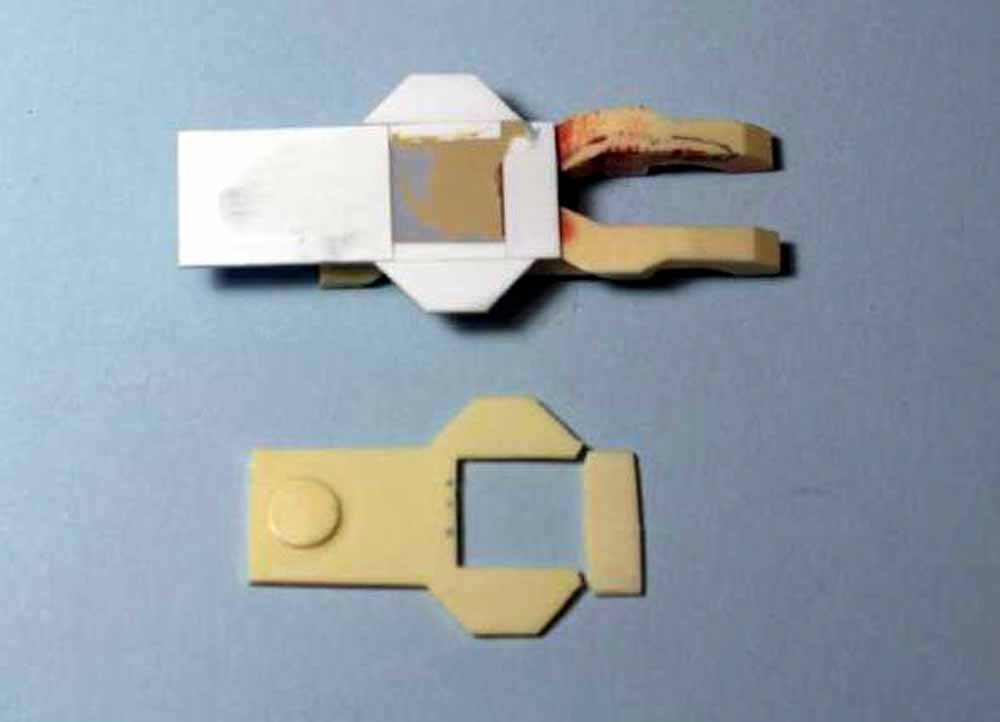
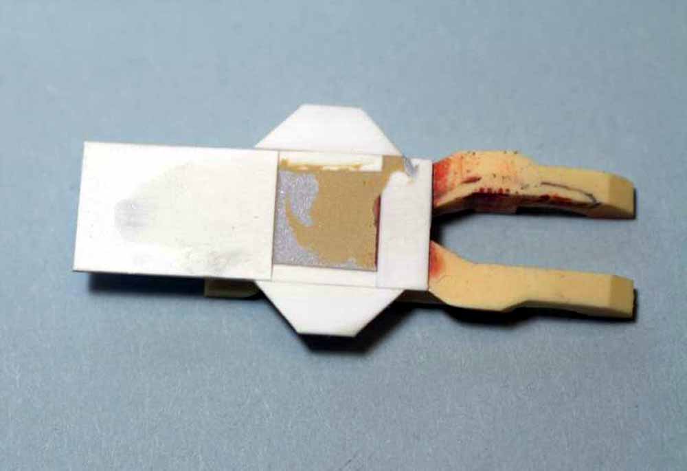
Fig.66 Probably the most difficult thing to mold in resin is a hollow part, stacks are a prime example. Most resin kits have at best a 1/8” to 3/16” deep recess cast into the top of the stack. I prefer a much deeper recess so the stack looks hollow. Very carefully you can drill or grind out the stack, I do mean VERY carefully. In this case I used pinvises and drilled through a 1/8” hole, after using a .040” bit to drill a fairly deep pilot hole. Then I used 5 more bits and gradually reamed the hole up in diameter, you can see in the second photo that I did not try to go full diameter for the full depth and left small steps deep inside. Finish up with some 400 grit paper wrapped around a bit shank. Once mounted and painted black inside you will have the illusion of a hollow stack.
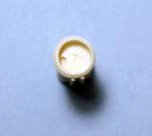
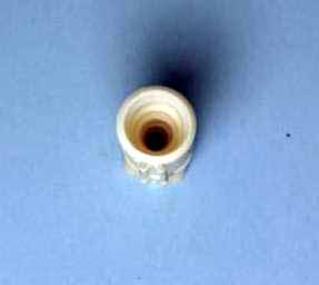
Fig.67 The stack and uptake subassembly ready to prime and paint. To make the torpedo base use a hole punch and then lightly sand any burrs off the edge. Mark its location and glue in place, since it’s styrene to styrene here I used regular liquid styrene cement. Then mount the stack with CA. In both cases hold the uptake in place on the hull and check alignment before applying glue. After letting the CA for the stack cure add the steamline for the whistle from .020” rod. Next take a piece of .020” thick strip and cut a platform, make sure to slot it for the steamline, CA in place. Add two small braces under the platform of .015” rod and lastly add a small bit of .030” rod for the whistle body. Set this aside until it’s time to paint, I’ll add the PE stack grate, ladder and railing for the platform later.
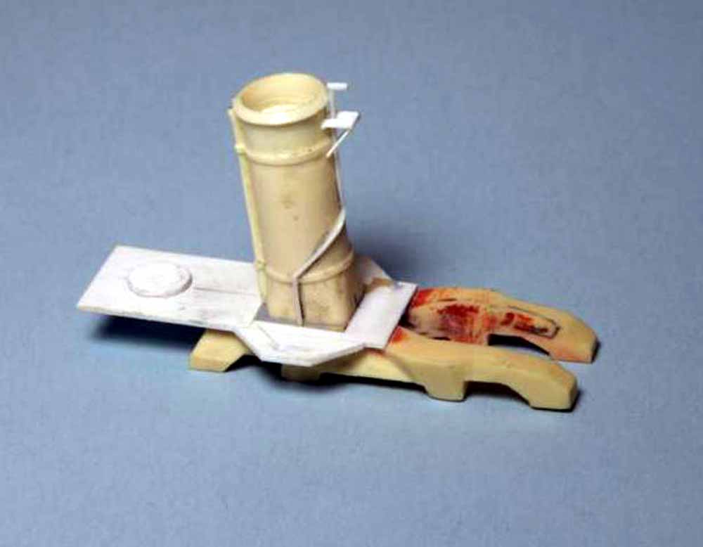
Fig.68 Most resin kits simply supply a solid bridge with window framing, this kit has a hollow bridge with some minor detail inside and PE window frames. I’m going to add a few more details after the basic painting is done. For now we need to enclose the bridge and do any needed sanding. The kit supplies two PE bridge faces, for the Somers and Warrington as built use the Somers bridge face, we’ll also use a bit of the Sampson bridge face. The Somers bridge face only gives you the window frames, the door sections are cut off the Sampson part. First bend and fit the window frames, I needed to trim away a little resin where it meets the splinter shield. Once you’re sure the fit is good, CA in place and file the resin along the deck edge so it’s flush on the outer face. Next cut the doors off the Sampson part, just cut along the fold line and file/sand the edge so it’s straight. There is a box on each side of the pilot house you need to cut away with a scalpel. Fit the parts as shown and CA in place, I ran the CA along the inside to avoid having excess in those tight exterior corners. I’ve also added two PE liferings from my spares box. Drawings and photos show an airtight door here, not a watertight door, I’ll add some from my spare PE frets later. At this point check the fit of the roof part but do not glue in place yet.
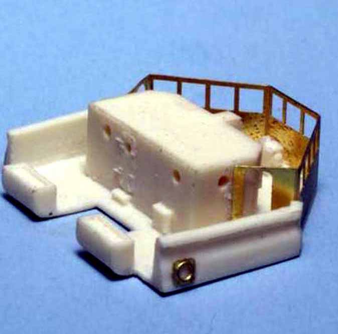
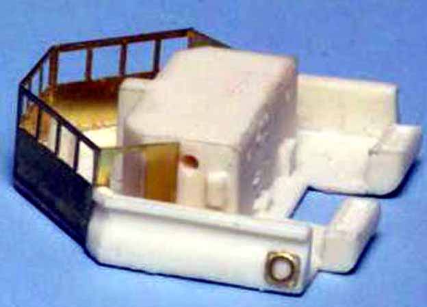
Fig.69 The last thing to do before setting the bridge assembly aside for painting is drill the signal halyard holes in the flag bags. The Somers class as built had five halyards per side. I use a .010” or .0125” bit for this, much smaller and you just end up breaking a lot of bits. Drill the holes at least 1/32” deep with 1/16” being even better. Had these been white metal flag bags I’d have cleaned up one and cast copies in resin, white metal is a real pain to drill with bits that small and it tends to eat bits like a kid eats candy.
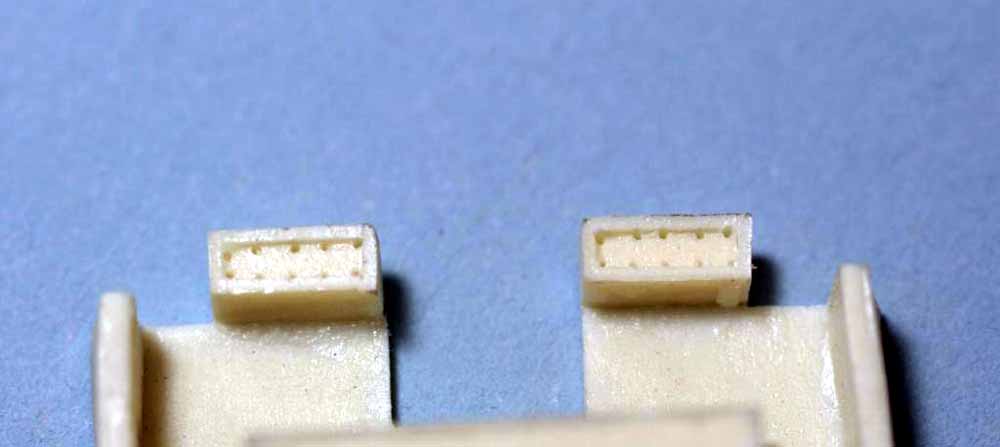
Fig.70 Next we want to cleanup the torpedo tubes and turrets. The torpedo tubes have been cut from their pour blocks, they have a few minor defects. There is a little flash between the tubes forward, a quick scrape with the edge of a #11 scalpel removes it. There is a little excess resin between the tubes underneath but this is not really visible once the tubes are mounted, you can carve it out if you desire. The final minor defect is the back end of the tubes isn’t round, it’s slightly stepped but it’s an easy fix I’ll show you in a few minutes. The turrets have no pour blocks per se, they just have a little excess to the base that fits into their mounts. Razor saw 2/3 of that off. The defects the turrets have are minor amounts of excess resin from mold damage. On the bottom simply file it off taking care to preserve the chamfered edge at the rear of the sides. There is some inside the gun slots, carve it away with a microchisel.
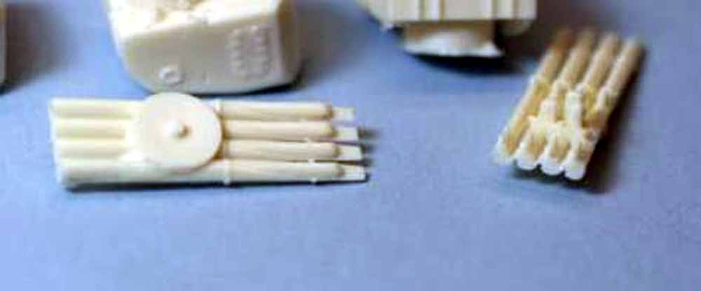
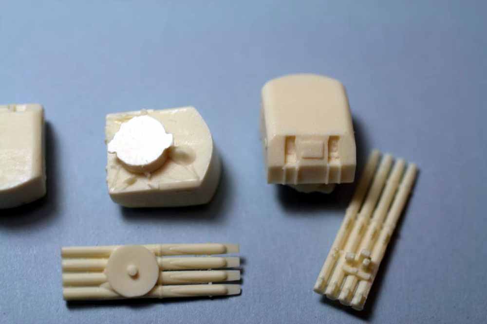
Fig.71 I will be using L’Arsenal 5”-38 brass barrels instead of using either of the two styles of kit supplied white metal barrels. The kit barrels are all badly stepped, to the point that sanding them round would leave half the original diameter. The other problem has to do with how they sit in the turret. Prior to the war the Somers and Warrington rarely had blast bags mounted, in fact Somers never shows blast bags while painted in her prewar scheme. The rotator for the gun barrel is set well back into the turret as shown in the photo of Somers sometime in 1938 as shown in the photo. The kit barrels have the rotator protruding a good bit and it’s just easier to use the plain brass barrels rather then cut the mounting slot deep enough to recess the rotator. To prep the turrets drill a hole in the bottom of the turret base so you can glue a “handle” of styrene rod in for painting. Then drill two .031” holes in the faces of the gun slots to accept the shank on the L’Arsenal barrels. Make sure to get the holes lined up with each other. Dryfit the guns and check that they line up parallel from the side. There is a little wiggle room and getting them parallel from above is easy. DO NOT glue the guns in place at this time. The turret and barrels will be painted the proper color first and the gun slots then painted black, only then will the guns be glued in place.
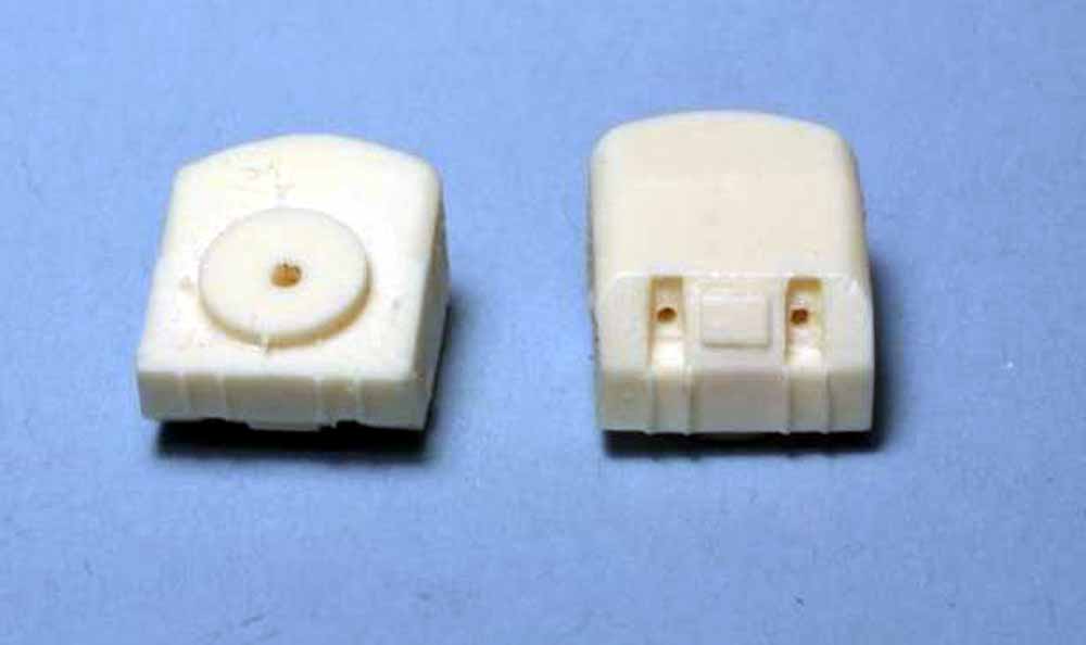
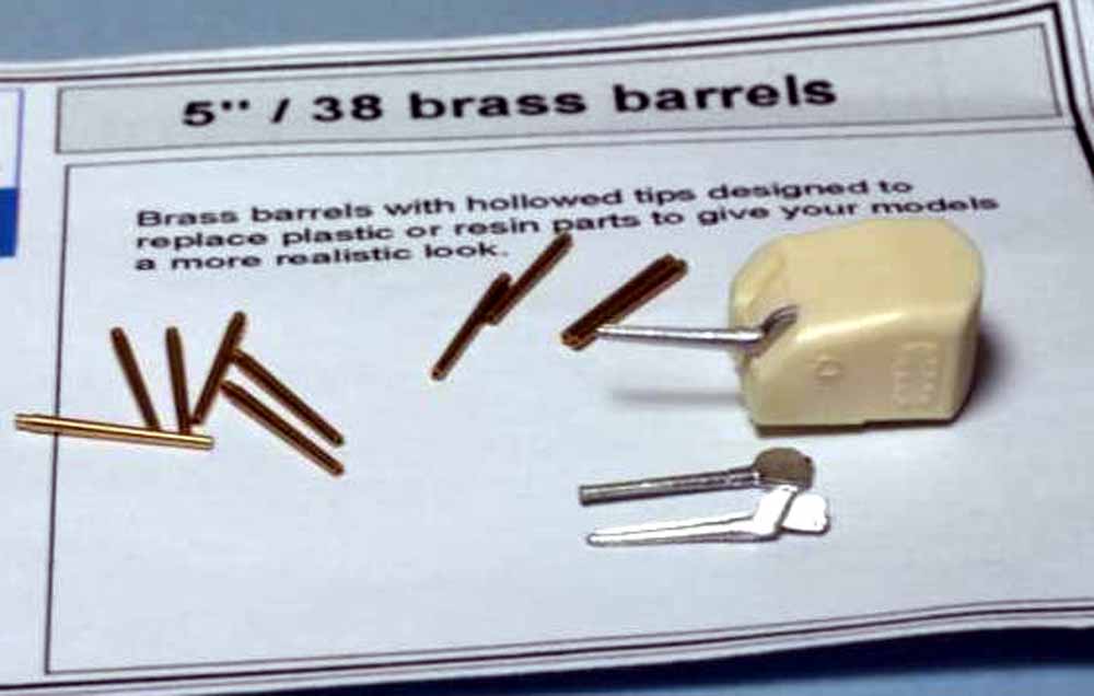
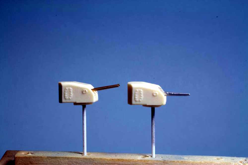
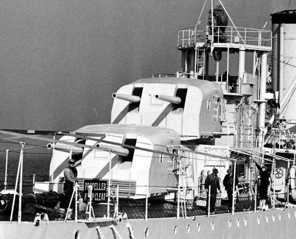
Fig.72 The only thing the torpedo tubes need, besides drilling a small hole in the bottom to take a styrene rod painting handle, is to hide the stepped back end. Using a Waldron or similar punch and die set make some .010” thick styrene discs .063” diameter. Use the point of a sharp needle to pick up the disc and carefully place it on the rear of the torpedo tube that already has a tiny drop of CA.
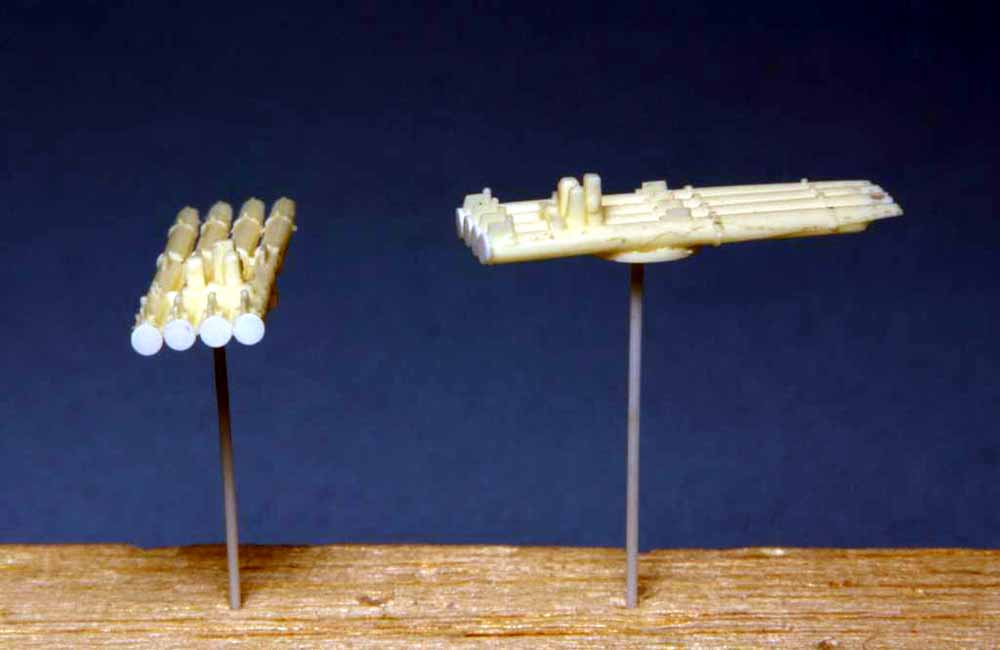
Fig.73 The kit’s white metal and PE 1.1” AA gun and two assembled L’Arsenal 1.1” AA guns. I’m using the L’Arsenal guns because I like the round barrels and extra little details better. The resin guns are very fragile but in typical L’Arsenal fashion are so well cast that separating from their pour blocks and clean up is simply a matter of a sharp scalpel and tiny bit of care. L’Arsenal gives you a small PE fret with handwheels, gunner’s seats and sight bar. To glue the handweels in place a tiny drop of medium CA on the gun base then lick the end of a toothpick and pickup the wheel with it, place it on the drop of CA.
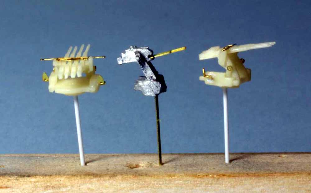
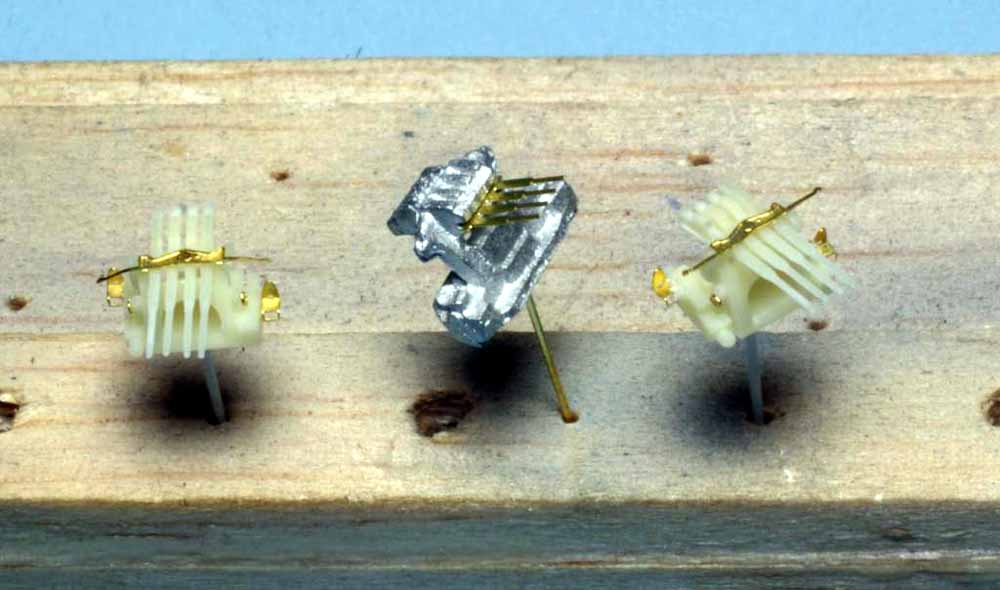
Fig.74 A few details need to be scratchbuilt. The three parts to the left are simply modified white metal parts from my spares box, I added some styrene bits and will use these inside the bridge, Shepard Paine dubbed this “creative gizmology” and in this scale it’s close enough to give an impression of detail. The four parts to the right are cowl vents, mushroom vents and a smoke generator, which the kit lacks. The mushroom vent was turned from brass on my lathe, I made four for this model. The two cowl vents are built up from bits of styrene rod to replicate those shown on the plans. The cowl vent is made up mostly from styrene rod CA’ed together. The bell of the cowl is 1/16” brass tube reamed out with a drill bit so the wall is only .005” thick then belled with the tip of a ballpoint pen. Carefully cut the bell off the tube with a razor blade saw and CA to the styrene, sand the outer part of the joint to fair it in. Then carefully take a drill and ream out the inside and drill into the plastic a little to give an impression of depth. The smoke generator is a quick resin cast copy of one from my spares box. Note the parts are mounted on styrene or brass rod “handles” stuck into a balsa block to make painting easier.
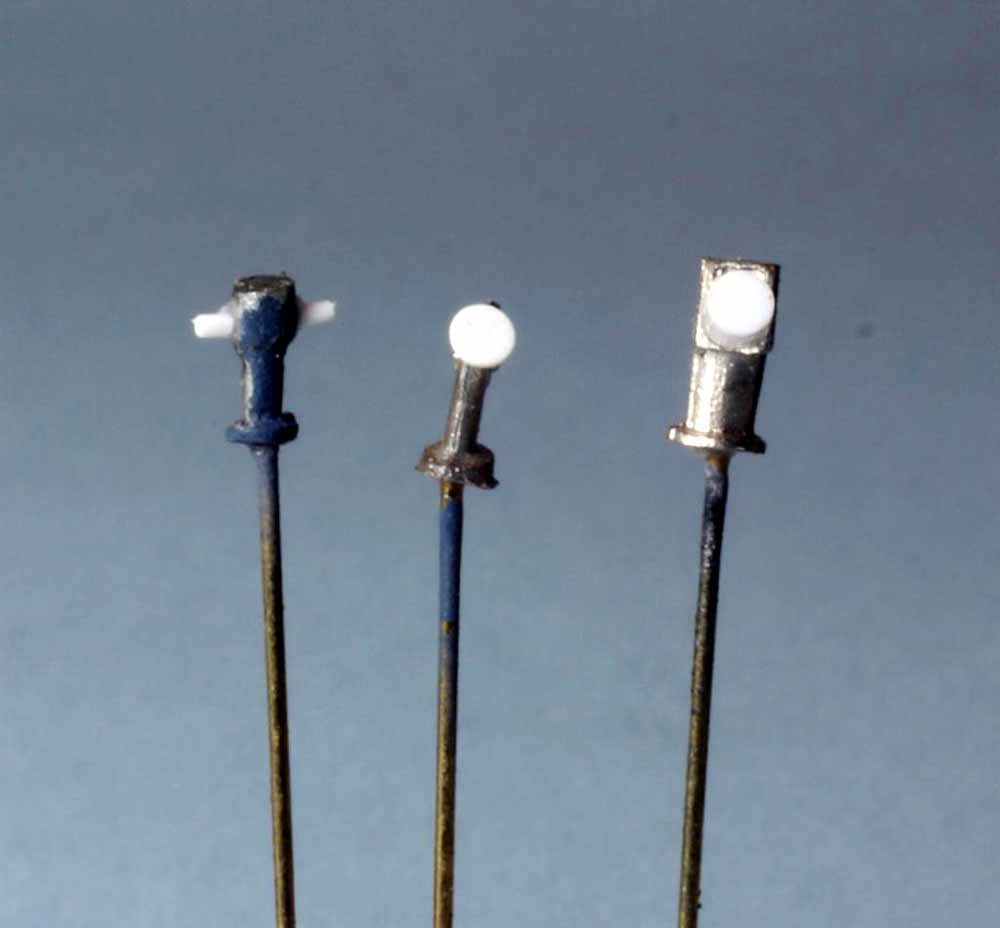
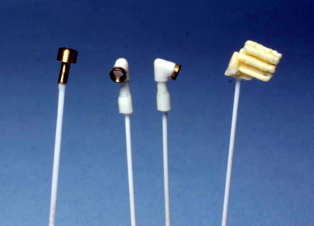
Fig.75 Cable/hose reels, rafts and boats. The rafts and boats are built right from the kit parts with just a little clean up needed on the white metal. Two of the boats have .0125” diameter phosphor bronze wire glued in place at the ends, these wires will replicate the ropes used to hang the boats from davits. I do not add the boat props until much later. The cable and hose reels are either from my spares box or a dedicated PE fret such as Gold Medal Models or White Ensign Models produce. The actual cable or hose is easy to make. Start by selecting a styrene rod that’s approx. .030” smaller in diameter than the PE reel end, we’ll call it the core. Tack a piece of .010” styrene rod perpendicular to the core with CA then tightly wrap it around, tack the other end of the .010” rod to the core with CA. Repeat as many times as you need reels in that core diameter leaving a small gap between sets of windings. Using Tamiya extra thin cement, lightly flood the windings and let dry, make sure the windings are not touching anything. I’ve tried other liquid cements and they all turn the windings into mush, the Tamiya cement is just aggressive enough to bond them to the core without turning them into a blob. When dry use a razor blade to slice the windings and core to the length needed. CA the reel ends in place then slip into the mount, insert a piece of brass rod and apply a little CA to hold things in place. A little paint and a light wash will make the windings “pop” and your reels will look like they’re properly wound with cable or hose. All these parts are ready to prime and stuck onto masking tape rolls; I find it handy to do this as soon as the part is done.
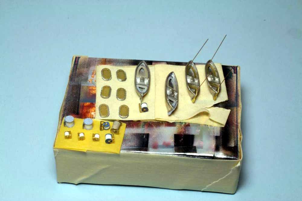
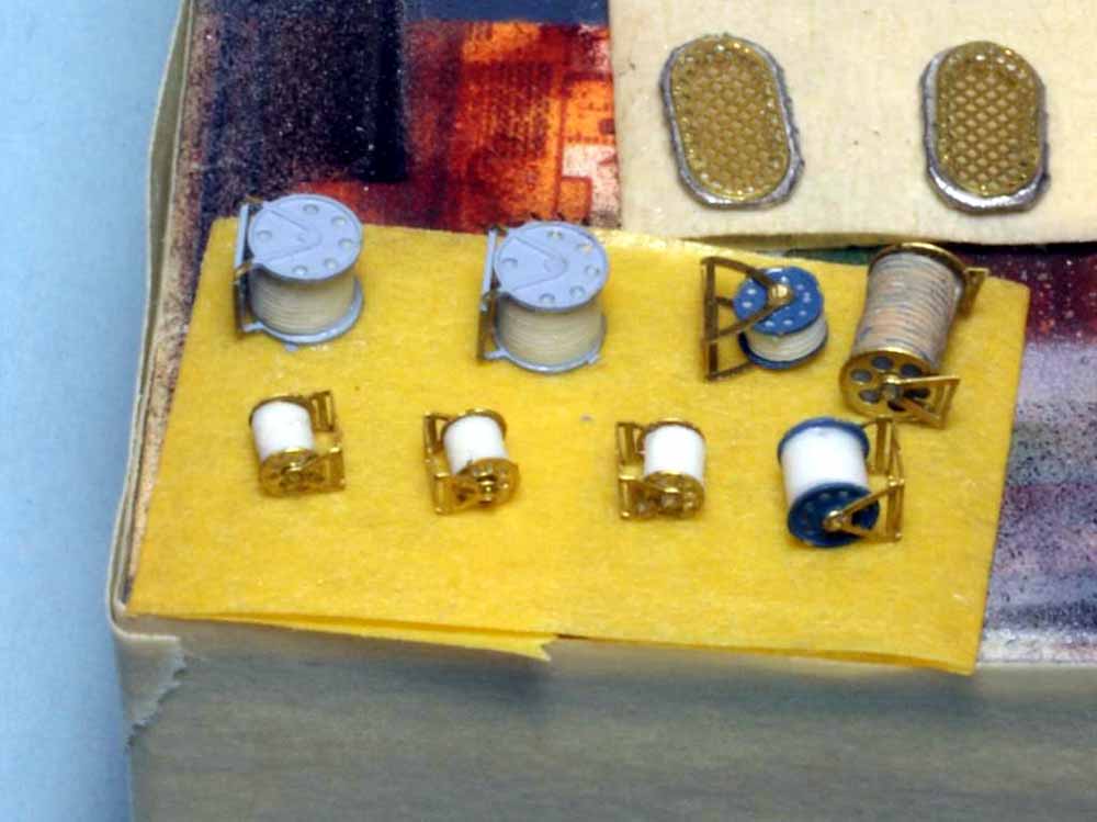
Fig.76 Everything is now ready to prime. The PE fret is taped to a piece of cardboard, the larger parts are stuck to rolls of masking tape on small boxes, the smaller parts are mounted on styrene rod, brass rod or toothpick handles stuck into balsa blocks, the barrels and crane parts are held by microalligator clips. You will need to paint some parts in two steps, start with those. I prefer to shoot the PE fret first with a light coat from each of the four sides of the fret and then use the tape on one end to hang it from a shelf edge to dry. Next I do the bottom of the hull and place it upside down on blocks to dry. Make sure to use a low paint volume and work all around the various angles for the prop shafts and supports before doing the rest of the hull bottom. Next I shoot the parts stuck to tape rolls again working from all four sides with light coats. Finally move on to the small parts with handles, use tweezers to pull them out of the blocks by the handle and put them into another block as you prime, this keeps you from crunching parts as you work. At this point I just clean my airbrush tip and cover the color cup with a bit of Parafilm and go away for 20-30 minutes while the primer dries enough to handle. Next flip the PE fret and tape it down so the unprimed side is up then remount the larger parts on fresh tape rolls so their unprimed areas are up. Repeat the priming process for the PE fret, larger parts on tape rolls and do the upper part of the hull. Clean the airbrush and allow the parts to dry at least an hour before any other painting.
That’s all the “hard scary” parts of building a resin ship, everything else is just like injected ships, follow the directions and glue parts in place after painting the major assemblies. There is no magic involved other than a few simple tools and the normal patience needed for modeling. Sometime soon the finished USS Somers will be in the gallery.
The current Yankee Modelworks kits have decent directions with most of the destroyers being similar to this kit. White Ensign Models destroyers have slightly better directions and less massive pour plugs with those on the hull being almost non-existent. So treat yourself to a new destroyer kit and then try telling me resin isn’t fun.
