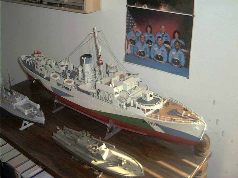
Matchbox 1/72 Scale Flower Class Corvette
By Tom Van Dermark
Matchbox 1/72 Scale Flower Class Corvette
By Tom Van Dermark
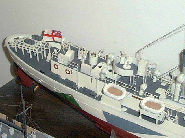
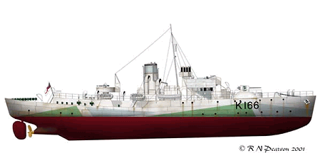
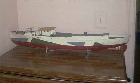
During the preceding months before World War 2 the British Admiralty realized that it had a shortage of convoy escort vessels so a design was approved that was based on a merchant-whaling vessel. The Flower class Corvette was designed so that merchant shipyards that where not ordinarily utilized for wartime production would be used to produce them. The power plant was designed so that no special training was needed to maintain or repair them and most replacement parts could be made at a local metal workshop. The Flower Class Corvette was used in every theater of the War but is mainly remembered as a workhorse in the Battle of the Atlantic. The kit I am using is the 1/72nd scale Flower Class Corvette by Revell and my main point of reference is the book by Warship Perspectives, Flower Class Corvettes in World War 2 by John Lambert. The ship I decided upon was the H.M.C.S. Snowberry as she appeared after her refit in May 1943, but she can also be built as she appeared before this refit with a shorter focsle and the mast forward of the bridge.
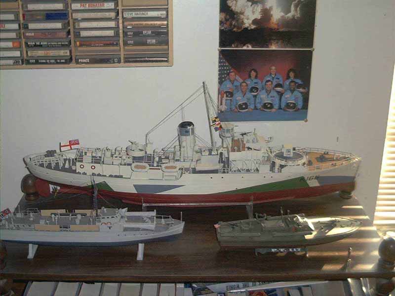
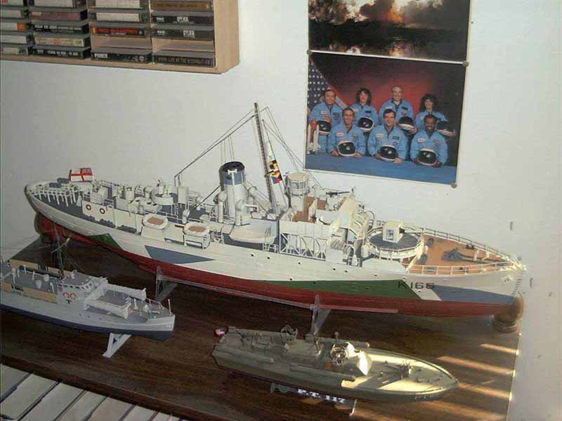
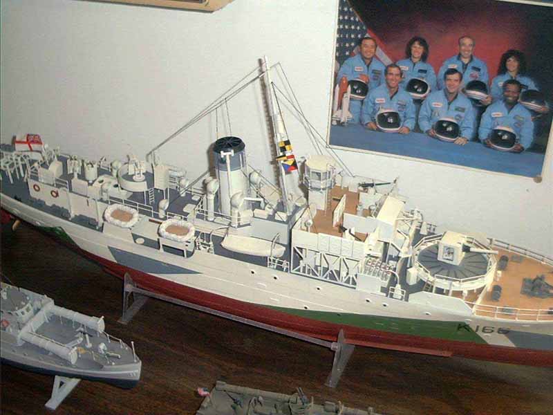
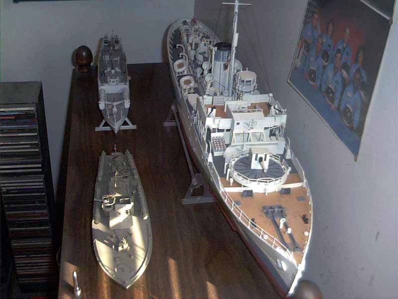
The first thing you will notice when you are building this is the immense size of the kit. This thing is huge! If you thought the 1/350th scale Bismarck by Tamiya is big, well guess what, that whole kit as built will just about fit into just the hull of this little darling. The second thing you will notice upon starting assembly is that you will need a lot of glue and just as much putty. This is definitely an old kit that will need a lot of work but still can be made to look nice just out of the box. There are many after market detail sets available from overseas so much so that one manufacturer claims the only thing you will need out of the kit is the hull. For this build I wanted to try to keep it built as out of box as much as possible with a few minor corrections and replacing of kit parts.
Click on thumbnails for larger images
Construction started with the hull of course and the first step was to remove the molded on Keel block that is molded on the whole length of the ship. On the real ship the keel block came from the bow and extended straight down and was blended into the hull bottom. The ships rudder shaft was drilled out to accept a 1/8th inch brass rod, I do this to add strength to this obviously weak area, there have been to many times when I broke off a rudder by barely touching it. While the hull was drying I started to remove the modeled wood planking on kit parts C1 and C2. The deck on these ships were mostly metal plate, except for the bow section starting just aft of the breakwater. I would also strongly recommend that you reinforce kit Parts D1, D2, D4, D8 and D9, not only do these part keep the hull from flexing in and out but also support the main deck so either use a long piece of sprue or better yet just superglue a metal rod on each side of these pieces. It would also be a good idea to replace the propeller shaft at this time; once again I drilled out the appropriate pieces for a 1/8th inch rod. Yes you do have to reinforce a lot in this step but it will be well worth it later on in assembly and any time that you transport the ship when you are done with building it.
The hull is broken down into four halves so I decided to glue the two Port (left) side pieces and the two starboard sides together so that I can have as good a seam as possible there and work on filling the gap that resulted down the middle of the two halves. This turned out to be just about the best way of doing this but resulted in a gap that I could not get out at the very stern of the ship, but lo and behold when looking at the directions I found out later on that is right where a support beam goes. All horizontal decks where to be painted neutral gray so this was done, as was the natural wood deck at the bow of the ship. The hull was painted a dull white by using Polly scale flat white mixed with a little dirty white to tone this down a little. The camouflage colors I used where US intermediate blue A/N 608 and RLM 83 light green lightened with flat white, now before anyone has a conniption about what colors actually belong let me say this, I went by the old tried and true standard of "yea that looks about right" so live with it. I also used Polly scales red (RLM 23) darkened with a little flat black once again using the same color standard. I have a picture that shows this ship sitting in port riding high and you can see that there is no black boot separating the camouflage color and the antifouling coating so this was left off.
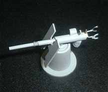
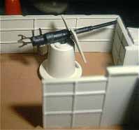
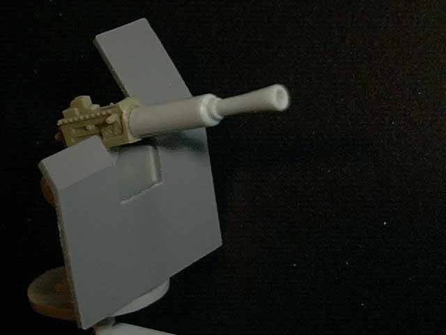
The instructions dont really say so but they do give you parts for two different gun houses for the 4-inch gun. I decided to use the early square gun housing and also decided to open the forward view ports. In order to replicate the blast bag I used a tissue soaked in Elmers glue and shaped it with a putty knife and a #11exacto blade. . After this was dry I touched it up again with Elmers glue. I am using decals made by a man by the name of Bob Pearson who has made these on his Alps printer. The kit decals for the gun housing are pretty sorry looking but the ones I received from him where definitely worth more then I paid and I cannot recommend them enough. Included in the purchase priceare paint schemes for 11 different Flowers and also full size templates for converting this kit to any of the 11 different ships including short focsle Flowers. He also has an excellent site that you can visit on the net for articles on how he built his ship and a lot of pictures and very good information at Bob Pearson's Flower Class Corvette website. For the deck on the gun platform I used masking tape cut into 16 thin strips painted grimy black to represent the non-skid strips and put these in a circular pattern around the assembly. In this scale it looks like a good representation. The instructions also say that the ammunition holders dont go completely around the base but according to my pictures of the Snowberry they do, so that is how I assembled mine. The vents that come with this kit look like big pieces of macaroni so I hollowed out the face of each with a drill and then shaped that with a dremel to make it appear more realistic. Using a ball of twine, I cut a small piece and then separated that in half lengthwise and starting on one side of the cable reel wrapped the twine around until the spool was full then superglued and painted it grimy black.
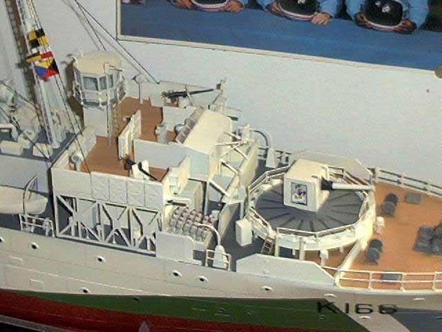
When building the bridge if you follow the directions it will tell you to build up the sides on a flat piece of wood or suitable surface, I have heard of many complaints about this and come to find out what you want to do is actually build the bridge upside down on a flat surface. This will result in the top being flat and the bottom to conform to the shape of the deck. There isnt any really pronounced slope to the deck but it is there and if you flatten out the bottom you will just have to fill it again later. All the storage lockers needed at the very least sanding and filing, for those who wish to do so it might be easier to scratch build these. When assembling the hedgehog assembly the blast board towards the rear is supposed to sit flush with the deck so I just removed the molded on locating line and glued it to the deck. It is a little confusing to see but kit parts M1 and M11 when assembled go on the bottom of part D14, when I was test fitting mine I was wondering why it fit so well compared to every other assembly, then I noticed that I was mating them wrong and that solved that little dilemma. I am trying to remember that this is an old kit and it is a lot of fun to build but it suffers from a lot of sink marks and gaps so just be aware that if you want to fix them all you will be spending a lot of time filling and sanding. You can help yourself sometimes by looking ahead in the instructions and seeing whats next in the assembly and skipping a few steps. For example I glued parts E7, G4 and G55 together, then glued this onto the upper part of the bridge so that I could have at least 3 good seams and fill 1, which is better then if I glued it the way I would have if I followed the instructions. (See, thats why real men dont follow directions, we know better!).
The 20 MM guns that you receive as is are laughable, but once again trying to use as many kit parts as possible I drilled out the barrel, reshaped the ammunition boxes, added gun sights from my spares box, added spent cartridge bags, added recoil springs, and replaced the shoulder supports. This was accomplished by removing the molded on support then using wire to shape the supports. The blast bags are duffel bags that I cut in two then added to the bottom. The recoil springs where made by taking a normal piece of electrical wiring stripping off the outer plastic grabbing 1 piece of the copper wire and wrapping it in circles around a like size drill squeezing this together and gluing them onto the barrel of the gun, it sounds more difficult then it actually was and made the guns look pretty good or at least better then before.
Moving onto the upper bridge assembly do not hollow out kit parts k44 these are voice tubes; these had a flapper over the top when not in use. I removed the top to the compass platform and pinnacle and using instrument decals from my spare box I placed these on and used Elmers school gel to replicate the glass covering. The type 271 radar platform has dimples molded onto it, these where drilled out. Once again the kit doesnt say so but they do give you two different lantern designs both early and late. Using the pictures I have I will be using the early style. After test fitting the upper part of the radar housing I noticed that unless you remove the molded on locating lines that piece will be off center so I used the holes that I drilled into the platform to guide me when it came time to glue that piece on. The Clear plastic windows for the radar housing was worthless because they didnt even come close to fitting right so you have the choice of either replacing these or just throw some canvas colored tissue over the whole assembly and be done with it. Me unfortunately I decided to try to make my own windows. The signal flag storage locker looked pretty dumb as is so I went ahead and made a copy of the signal flags given in the kit reduced them a little bit folded them in halves until they where small enough to shove inside each of the compartments. This helped out the overall look of this piece and the bridge.
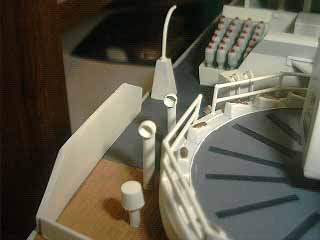
When installing the engine room vents remember that the upper part of these vents rotated 360 degrees depending on prevailing winds. So according to the pictures I have seen they could and did face any way you want them too. As far as the exhaust funnel is concerned the kit one supplied really isnt that bad, the bracing on top looks nice so all I did was paint a intermediate blue stripe around the upper portion of the funnel and then the rest the same white as the rest of the ship. I then drilled holes in the funnel and the deck according to the directions. For most of the guide wires and rigging I am going to be using either 24-gage brass wire or .020 stainless steel safety wire. All the various piping that surrounds the exhaust funnel where drilled out. Some of these where very thin so I drilled to a depth only sufficient for the look and will fill the hole later with a black wash giving it a little more depth. The main mast was completely redone using various diameter and lengths of metal rod. This gives the assembly a lot more strength and rigidity when it comes time to do the rigging. A good straight edge for doing this is the kit ladder that attaches to the backside of the kit mast. If you build the various lengths up on this piece you should be able to keep it pretty straight. On Kit part M56 (Engine room skylight) I used my dremel tools to open up the round skylights, if you choose to do so you can remove the square molded on covers and replace them with sheet stock and open these up as well the hinge is on the inner side and they open roughly parallel with the deck. When assembling kit parts M6, M7, M16, and M22 I was going to open what I thought where porthole on each part but upon further inspection I found out that these were not portholes but rather some kind of vent. I didnt try it but it looks as though if you hollow out these molded on squares and replace these with some kind of small mesh screen it will look better. Also remember that kit assemblies 113,114,115, and 116 (smaller vents) also had the ability to swivel 360 degrees, on my kit I just faced them all forward but at least if someone comes up and say all your vents are not dead on straight I can in all honesty tell them thats the way they are supposed to be.
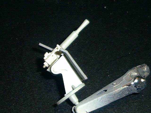
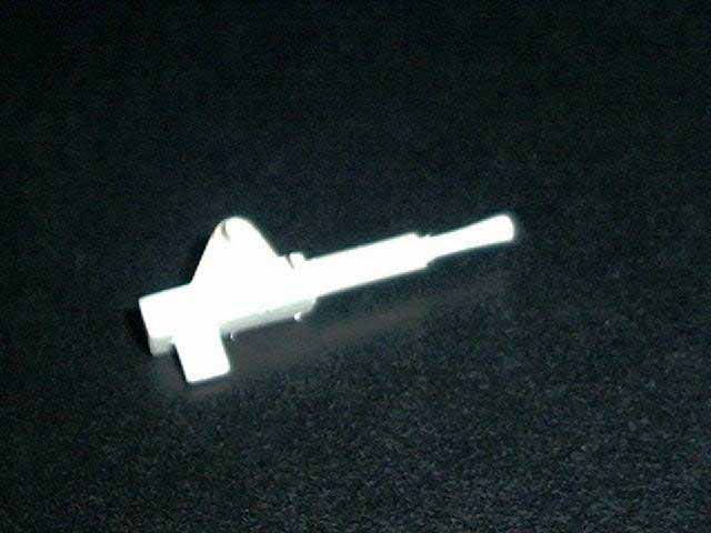
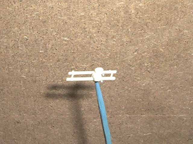
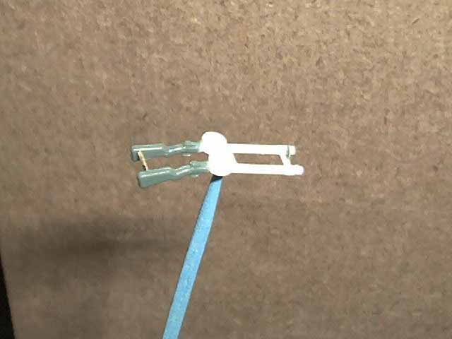
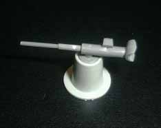
On the twin Lewis machine gun I replaced the breach mechanism on each gun from my spare box. As molded they look like twin rods with no detail what so ever. The Barrels where drilled out with a # 75 drill and then glued to the mount. I also added a gun sight that was actually from the King George V Photoetch set from Gold Medal Models. It seems that if you look at the left overs in this set you will notice that the crane pulleys will look like good gun sights so these where attached to the middle of the support. It might be a good idea to either leave the shield off of the mount for these guns or try to make some yourself as the kit shield are entirely to thick. The 2 pound Mark VIII was also given a much better breach assembly by once again going to the spare box removing the muzzle of the kit supplied gun drilling that out and giving the bore a flare twisting a # 11 exacto-blade around the bore, then super gluing this onto the new breach. This is where you are going to have to make a major decision and that is on the 2 Pounder the splinter shield has a molded on gap where a ladder attached, but according to the pictures I have this shield wrapped all the way around. The only way you can fix this is by removing the molded on shield and replacing it with sheet styrene. In this case I decided to leave it alone rather then having to rebuild everything that attaches to this assembly.I know this seems like a lot of work to do on the guns but you will be happy with the results.
I have to admit that if there was anything that I wanted to change in the way I am building this kit is that I would have seen if I could have gotten some kind of replacement railings. The way the kit has you do it is basically build it from various lengths of straight sprue or thread. Overall the railings I am doing would pretty much take me out of any contest that I would enter with this kit. It is extremely difficult to get all the railing straight and true. There has to be some better way of doing these maybe the model railroad industry has something or what ever but I would really look into replacing them. Given the time taken to cut and measure each individual section gluing them on and trying to keep them straight and the final result just isnt worth it.
Now I have to say that some people can get the impression that I am bad mouthing this kit but in my defense I have to say that is not the intent of this article. Trust me I would have never spent this much time and effort on a kit that I was not having fun building. Can this kit be built into a contest winner? My answer is most definitely yes, can mine win?, not by any stretch of the imagination! But in the long run I am having fun with it and that to me is more important than the final result.
Moving onto the life raft supports and the rafts themselves. When building the supports remember I temporally mounted them to the place that I would be gluing them too later as the angle that they belong is pretty tough to just eyeball. They life rafts they give you are pretty nice and can use a couple of add on features like a set of oars and various size boxes for survival gear. The only problem I found with the raft where the line up and resulting seam. In order to negate most of this simply remove the raised inner step on the bottom of each assembly and that should result in a much better fit. The life boats are also nicely molded once again with more then enough space for detailing or if you so choose you can use tissue paper and simulate the canvas covering.
The depth charges where assembled next as where the depth charge throwers and the stern racks. Once again the kit gives you the option of two different types of depth charge racks. On most of these ships unless the ship was fitted with minesweeping or towing gear fitted to the stern they used the long racks. Once again it all seems to depend on what ship you are modeling as to what gear you should use.
At last it seemed as though I was done with the overall assembly and all I had to do was run the rigging. Like I said before I used 24-gage brass wire. In order to get the wire taught I grabbed both ends with two pliers and pulled as hard as I could and snipped off the two ends. This was then measured and super glued to the area where needed, and painted black. You can use the kit supplied thread but of course that is exactly what it will look like black thread. Also I have noticed that when you use thread it never seems to be tight enough and always has a very pronounced droop. The brass wire will never droop and will stay right where you put it.
After
this was left to dry I went ahead and gloss coated the whole thing let
that dry and then applied some signal flags, the Canadian Flag and various
other decals. After these where left to dry I then dull coated the entire
assembly. Then moved onto filling in all the portholes and the glass windows
on the radar assembly. On the portholes I used Elmers gel type glue this
has a little ting of blue to it and when dry looks nice. As far as the
radar housing windows I used regular clear sheet styrene cut into individual
panes and then glued on the inside of the housing. I have also heard of
people and seen pictures of the whole radar housing being covered by canvas
when the ship was in port. The kit also gives you a few figures in different
poses that you can place on board but my figures needed to much work and
at this point I didnt really want to deal with them so these where left
off and I was done with my Corvette.
I was quite surprised with the amount of time
it took to build and the amount of fun I had with this kit. Yes there is
a lot of work that you need to do to it and yes you can definitely tell
it is an old kit but boy did I ever have a good time building it. I guess
one of the drawing factors to the kit was it is most defiantly a different
subject and when complete it does look impressive. I would recommend this
kit to everyone who has enough patience to build it but also it would be
a good father, son project to complete. In some ways after I was finishing
this kit up I kept remembering building for the first time that great big
1/72nd scale B-52 Stratofortress when I was much younger. I
guess just the sheer size of these kits had a lot to do with how much fun
they where. Gee I wonder what Freud would say about that! Till next time
Happy modeling